
9 minute read
Repair instructions

from Volvo Penta 280, 280-DP, 285, 290, 290-DP SP-A, SP-C, DP-A, DP-B, DP-C Drives Workshop Manual - PDF

Upper gear housing
Disassembly, models 280, 285 and 290
1. Remove the shift rod (1) from the shift plate (2). Remove the screws (3) and the nuts (4) holding the intermediate housing to the upper housing. Use a rubber mallet to knock the housings apart. Knock carefully.
3. Remove the 7 screws holding the lower gear housing to the intermediate housing. Use a rubber mallet and knock the housings carefully apart. Lift off the splines sleeve (1).
NOTE! On sterndrives of later manufacture the 4 bigger-sized screws are installed with stainless steel washers. Take care of these washers.
2. Keep check on the number of shims (1) between the different housings and for all the gear sets in case neither the gears, housing nor the bearings need to be replaced. In this case the same shim thickness is to be used.
884264 884830
NOTE!
NOTE!
NOTE!
11. Remove the needle bearings (1) and the from
NOTE! The needle bearings are matched in pairs and must not be mixed!
NOTE!
884265
884386
Input gear (Double bearing box)
NOTE! Do not damage or lose the
NOTE! Always replace
884259
884386
18. If required press off the roller bearing (1) from the gear using a knife puller. The bearings (1) and (4) can be changed separately. When changing the outer races of the bearings, these must be ”knocked” off. Knock evenly all around. Always replace the oil deflector washer together with the outer races. Wash the parts and check for wear. Replace parts when necessary.
NOTE! Gears with cones are sold in sets in order to obtain the correct gear contact.
Assembly, models 280, 285 and 290
NOTE! When assembling the upper gear housing it is very important that the gears are correctly positioned in relation to each other. This applies not only to the backlash between the gear teeth but also to the gear teeth contact. Correct gear teeth contact spreads the load to which the gears are subjected over a larger area of the gear tooth. This preventing gear breakdown and abnormal wear and at the same time providing a quiet operation.
3. Rotate the bearings a couple of turns to allow them to ”set”. Check the prestressing with a spring scale and a piece of string, tied around the bearing housing. The prestressing should be 5–10 Nm (3.69–7.38 lb.ft.). Should the prestressing be too low, press the roller bearing carefully a bit harder and if the prestressing is too high, release the roller bearing somewhat.
NOTE! With run-in bearings the prestressing should be 2.5–5 Nm (1.84–3.69 lb.ft.)
NOTE! Protect the tips of the gear teeth.
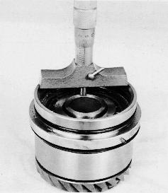
4. Determine the measurement “B” (fig. under point 5) as follows: Use a depth micrometer and read the measurement “C” between the edge of the double bearing box and the inner ring of the bearing and measurement “D” between the edge of the double bearing box and the edge of the gear. Then calculate the difference.
5. Measure the depth of the recess in the collar washer “E” and add to this measurement a number of shims (5) that the measurement “B” is obtained.
Forward and reverse gears
6. Place the collar washer in position and tighten the double bearing box. Use special tool 884483 and the universal joint screw.
NOTE! Coat the screw with Loctite locking fluid or its equivalent. The tightening torque should be 75 Nm (55 lb.ft.). Rotate the double bearing box a few turns and check once more the prestressing (5–11 Nm, 3.69–8.11 lb.ft.). Should the prestressing be too high, remove the recessed washer and press back the gear wheel somewhat. Then add more shims underneath the recessed washer. On the other hand should the prestressing be too low, reduce the number of shims. Then tighten the double bearing box again with the screw and the special tool 884483 and check the prestressing.
7. Lubricate the bearings (1) and press the bearings into their respective bearing boxes (2).
NOTE! Turn the bearings with the recesses in the bearing races (3), for the assembly of the balls, facing away from the gear wheels. Use special tool 884168. Then press on the bearings and the bearing boxes onto the gear wheels (4). Use special tool 884265
NOTE! Protect the gear cup (5) during the compression to avoid that it is being deformed.
8. Always start by adjusting the forward gear. If the previously dismantled gears are to be used, it is important not to mix forward and reverse gears with each other when assembling. On sterndrives having left hand rotating propeller as standard, the lower gear is the ‘forward’ gear (1). Sterndrives having right hand rotating propeller as standard, the upper gear is the ‘forward’ gear (2).
Shimming the forward and reverse gears
Method 1
B88 C78
11. Only the decimal values of the “B” and “C” dimensions are stamped into the upper gear housing. The nominal value for both “B” and “C” is 61.00 mm (2.40”). Add this value to the value stamped into the gear to calculate shims for the forward and reverse gears.
The shim calculations can be seen in the example below:
9. Measurement “A” is fixed at 62.05 mm (2.443").
Measurement “A”: 62.05 mm(Fixed Dimension) + 0.05 mm(Gear Etching 1)) 62.10 mm
“C” Stamping:- 61.78 mm(Stamped 2)) 0.32 mm (0.013”)
The shim thickness for the forward gear is 0.32 mm (0.013”).
The shim thickness for the reverse gear is calculated the same way, only using the “B” stamping.
1) Only +5 is etched.
2) Only 88 (B) respectively 78 (C) is stamped.
+0.05 mm
10. Add or subtract the plus or minus marking (1) of the gear.
NOTE! a + 5 marking = +0.05 mm (0.002”).
NOTE! When calculating the shim thickness for the forward and reverse gears, remember:
The upper gear housing nominal dimension has two values.
If the stamped number is 50 or more, use the lower nominal value, 61.00 mm.
If the stamped number is 49 or less, use the higher nominal value, 62.00 mm.
Example:Stamping 50 or more
“C” stamping: 78=00.78 mm
Use Nominal Dimension=61.00 mm 61.78 mm
Example:Stamping 49 or less
“C” stamping: 43=00.43 mm
Use Nominal Dimension=62.00 mm 62.43 mm
Then follow the procedure in chapter Checkingthe gearbacklashandcontactpattern
Checking the gear backlash and contact pattern
Method 2
12. Insert a 0.2 mm (0.008") shim (1) under both forward and reverse gears as a starting point. The shim value is a number derived from experience. Then follow the procedure in chapter Checkingthe gearbacklashandcontactpattern
13. Install the forward gear with the calculated shims into the gear housing. Insert the needle bearings and the vertical shaft. Install reverse gear into the gear housing using the needle bearings as a guide.
884387
16. Install the preassembled double bearing box with 0.4 mm (0.016") shims.
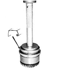
NOTE! The guide pin (1) in the double bearing box must be turned to face downwards and pressed into the corresponding groove in the clamp ring. Special tool 884483 is still being used.
17. Install the clamp ring and the cover with sufficient number of shims to ensure a proper compression of the bearings. There must be a clearance (1) between the housing and the clamp ring. See also the picture under point 19.
18. Install a dial indicator to measure backlash. The correct backlash should be 0.15–0.25 mm (0.006–0.010"). Should the backlash be too small, more shims must be added between the double bearing box and the gear housing. If the backlash is excessive, shims must be removed. A shim thickness of 0.10 mm (0.004") is a safe adjustment value.
19. When the correct backlash has been obtained, dismantle the double bearing box and the clamp ring. In order to obtain a clear picture of the contact pattern, the gear teeth are coated with a thin coating of marking dye. Once again assemble the double bearing box and the clamp ring.
NOTE! The cover must still be installed with an excess number of shims (1).
21. Dismantle the gear set and compare the contact pattern to that of the picture “A”. This picture shows the desired pattern for the drive side of the forward and reverse gear. The drive side is the convex side of the gear. The dye pattern should be nearly oval in form and be positioned half way up on the gear tooth. It should be displaced towards the small end of the tooth (towards the gear cup) but not running off the end of the tooth.
22. If the dye pattern reflects a contact pattern as shown in picture “B” the shim thickness underneath the drive gear (double bearing box) must be reduced. The drive gear then moves towards the driven gears. The driven gears must then be shimmed out the same amount to maintain the correct backlash.
20. Rotate the gear in the correct direction of rotation (clockwise) while at the same time braking the gear forcefully by wedging a wooden brace against the gear cone. The marking dye is then pressed away from the contact surface thus giving a picture of the width and location of the teeth contact.
23. If the dye pattern reflects a contact pattern as shown in picture “C” the shim thickness underneath the drive gear (double bearing box) must be increased. The drive then moves away from the center.
NOTE! If the drive is moved in or out respectively, also the gears must be moved in or out in order to maintain the correct backlash. Having obtained the correct backlash and dye pattern, the upper gear must be dismantled and the marking dye removed. All bearings and screws must be lubricated prior to assembly, which is carried out after the reconditioning of the universal joint.
Final assembly
NOTE! The end of the engagement sleeve marked ‘TOP’ must be facing upwards on the shaft. On earlier models there is a drilled recess, which must be turned upwards. The engagement sleeve must rest lightly on the spring. Feel by hand to make certain.
3. Install the needle bearings (1) and the spacer ring (2) between the bearings in the lower gear and insert the shaft in the gear.
NOTE! The needle bearings are matched in pairs and must not be mixed up.
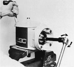
5. In order to obtain the correct axial shaft clearance there are 3 left hand threaded nuts (1) with different steps available. Select a nut and tighten it (tightening torque: 120 Nm (88.5 lb.ft.). Use special tool 884830 as a counter hold.
NOTE! Lubricate the treads to prevent the nut from galling.
4. Install the upper gear wheel with its calculated number of shims in the gear housing. Install the needle bearings with the spacer ring in between and the lower locking ring on the shaft.
NOTE! Carefully inspect the condition of the brass washer and replace if necessary.
6. Measure the clearance between the nut and the bearing. The axial clearance should be between 0.1–0.5 mm (0.004–0.020"). Should it prove impossible to obtain the correct clearance with either of the nuts, the bearing is probably defective.
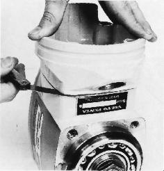
7. Measure the shim thickness between the clamp ring and the gear housing as follows: Hold the double bearing box as indicated in the picture with its calculated number of shims (see point 16, page 39).
NOTE! The guide pin! Add a sufficient number of shims to the clamp ring to obtain a clearance of max. 0.10 mm (0.004") between the clamp ring and the gear housing. Push the clamp ring into its position by hand and use a feeler gauge and measure the clearance all around.
8. Remove the recessed washer and the shims in it. Press the new sealing ring against the collar in the double bearing box, with the open part against the bearing. Use special tools 9991801 and 884312.
9. Install the locking ring (1) and the recessed washer (2) along with shims and install the O-ring (3) in the groove of the recessed washer. Use grease to get attachment.
NOTE! The guide pin (1) must fit the groove in the clamp ring. Install the washer (2) and the screw (3). At final assembly always use a new screw! Coat the screw with Volvo Penta part no. 1161053-2, locking fluid and tighten with a torque of 75 Nm (55 lb.ft.).
12. Apply Volvo Penta part no. 1161099-5, Permatex® no. 3 on the surfaces between the clamp ring and gear housing.
Install the double bearing box along with the universal joint in the gear housing. The guide pin in the double bearing box should be turned downwards. Lock the screws with thread locking compound, Volvo Penta part no. 1161053-2 and tighten them with a torque of 35 Nm (25.8 lb.ft.)
If necessary, recondition the universal joint. See chapter Reconditioning the universal joint, pages 62–63.
13. Install shims under the cover to obtain a clearance of max 0.1 mm (0.004") between the cover and the gear housing. Install the cover and push it into its position and measure the clearance with a feeler gauge all around.
14. Coat the contact surface with Volvo Penta part no. 1141570-0 sealant and install the sealing ring (1) in a way that the sealing for the front right hand screw aligns with the corresponding recess in the cover.
15. Install the calculated number of shims and tighten the cover.
NOTE! The front right hand screw is a hollow screw and shall be provided with an O-ring (1) under its head. Tighten the screws with a torque of 15 Nm (11 lb.ft.). Tighten diagonally!
