
3 minute read
Removing the sterndrive

from Volvo Penta 280, 280-DP, 285, 290, 290-DP SP-A, SP-C, DP-A, DP-B, DP-C Drives Workshop Manual - PDF

Models 280, 285 and 290
3. Remove the Allen-head bolts holding the zinc ring and remove it.
5b. Sterndrive model 290: Remove the cover over the shift mechanism and disconnect the shift cable from the shift plate and remove the swivel. Remove the screws holding the locking plate, then push the locking plate down.
4. Remove the oil drain plug and drain off the oil. Also remove the oil dipstick to facilitate the oil drainage. Replace the O-ring on the drain plug and on the oil dipstick.
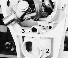
6a. Sterndrive models 280 and 285:
IMPORTANT! Carefully check the rubber bellows for possible damage and also check that the hose clamps are properly tightened.
NOTE! The universal joint bellows and its hose clamps should be replaced every other year. Contact an authorized service workshop and let them do the checking and replacing of the rubber bellows.
5a. Sterndrive models 280 and 285: Remove the cover (1) over the shift mechanism and disconnect the shift cable from the shift plate and remove the swivel. Then remove the shift cable locking plate (2).
WARNING! Never start working on the rubber bellows of the sterndrive until you have secured it in its raised position and then in a way which definitely keeps it up. A sterndrive ‘falling’ down can cause severe bodily injuries.
The suspension tool 884936, when properly installed, prevents the sterndrive from ‘falling’ down. The suspension tool locks the sterndrive in its raised position. Install the suspension tool as follows:
Press the retaining pawl (1) by hand downwards and lift the sterndrive, also by hand, to its fully raised position. Hold the sterndrive in this position while installing the suspension tool (2) as indicated in the picture.
NOTE! Do not overload the suspension tool by for example standing on the raised sterndrive!
It is also possible to raise the sterndrive by operating the sterndrive tilting motor sufficiently to allow the disassembly and assembly respectively of the rubber bellows.
NOTE! Secure the sterndrive in its raised position to prevent it from ‘falling’ down!
WARNING! Never start working on the sterndrive rubber bellows or on the hydraulics until the sterndrive is securely locked in its raised position in a way that it cannot ‘fall’ down. A sterndrive ‘falling’ down can cause severe bodily injuries. The suspension tool when properly installed, prevents the sterndrive from ‘falling’ down.
The suspension tool 885143 locks the sterndrive in its raised position. Install the suspension tool as follows: Press the retaining pawl (1) by hand downwards and lift the sterndrive, also by hand, to its fully raised position. Hold the sterndrive in this position and install the suspension tool (2) on the starboard side in accordance with the picture.
NOTE! Do not overload the suspension tool by for example standing on the raised sterndrive!
IMPORTANT! Carefully check the rubber bellows for possible damage and also check that the hose clamps are properly tightened.
NOTE! The universal joint bellows and its hose clamps should be replaced every other year. Contact an authorized service workshop and let them do the checking and replacing of the rubber bellows.
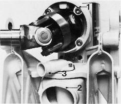
7b. Sterndrive model 290: Remove the steering helmet and the universal joint rubber bellows from the upper gear housing (1), the exhaust bellows from the intermediate housing (2) and the cooling water hose from the cooling water connection (3). The universal joint rubber bellows must be replaced every other year.
8b. Sterndrive model 290: Remove the two locking screws holding the shaft journals in the transom shield. Support the sterndrive from underneath and knock out the shaft journals using a brass drift or some similar tool. Lift off the sterndrive and place it in a suitable cradle.
NOTE! Always replace the bushings (1).
8a. Sterndrive models 280 and 285: Remove the two locking screws holding the shaft journals in the transom shield. Support the sterndrive from underneath and pull out the shaft journals, using special tool 884874. A brass drift can also be used. Lift off the sterndrive and place it in a suitable cradle.
NOTE! Always replace the bushings (1).
Models SP and DP
1. Disconnect power to prevent accidental starting.
4. Move control to forward gear.
2. Move control to reverse.
5. Remove the aft line cutter, forward propeller nut, and forward propeller. Return the shift control to neutral.
6. Remove the shift linkage cover.
9. Remove the two screws (1) holding the steering pin to the upper gear head (2). Using two M6 screws (3) 30 mm or longer, install into the threaded holes of the steering pin. As the screws are turned in, the steering pin will be forced out of the steering pin socket and steering helmet bushing.
11. Remove the cotter pin on the trim cylinder pin. Remove the trim cylinder pin. Raise the drive manually and insert special tool 885143
13. Remove the clamp on the raw water hose. Remove the raw water hose. Remove special tool 885143 and carefully lower the drive.
14. Remove the hook-up fork pin lock bolt. Using Pin removal tool 885148, pull the pin half way out of the transom shield.
WARNING! Do not remove the pins completely, the sterndrive will fall off the boat.
885146
