10 minute read
Introduction to Gas Turbine Engines


Turbine Engine and Propeller Systems
3 CHAPTER
Among a pilot’s responsibilities is to understand the basics of each system on the aircraft flown. Sometimes this seems excessive to pilots in training (especially those attending ground school for a new aircraft). It’s important, though, that a pilot be able to identify, understand, and rectify failures and problems that may occur in emergency situations. Therefore, most systems training emphasizes understanding of each system’s operating sequence, with special focus on what happens if various components fail.
The systems of most modern turbine aircraft are similar in operating principles and components. However, they differ greatly in the details of implementation. The result is that, once you’ve learned the systems on one turbine aircraft, others are much easier to comprehend. Let’s take a look at the basics of the major turbine aircraft systems. Then when you attend ground school, you can concentrate not on “What is it?” but on “How is it implemented here?”
Introduction to Gas Turbine Engines
The basic operating principle of a gas turbine engine is simple. Jet propulsion is described by Isaac Newton’s third law, which states that for every action there’s an equal and opposite reaction. In the broadest sense, gas turbine engines share jet propulsion with party balloons that have been inflated and released. In each case pressurized gases escaping from a nozzle at one end create an equal and opposite force to drive each of these “reaction engines” in the opposite direction (Figure 3.1).
The main difference between the balloon and the engine is in the source of the propulsive gases. The balloon is an energy storage device. Someone blows air into it, and once the stored air has escaped, the propulsion is over.
Gas turbine engines, on the other hand, are heat engines. Through combustion of fuel with intake air, they continuously create expanding gases, the energy of which is converted into propulsive force to move an aircraft. For this reason, the core of a turbine engine is known as the gas generator; it generates the expanding gases required to produce thrust. A nozzle is then used to accelerate the velocity of the high-energy gases escaping from the gas generator. By increasing gas pressure through its tapered chamber, a nozzle forces gases to exit through its smaller exhaust opening. The effect of this process is an increase in the momentum of air passing through the engine, producing thrust (Figure 3.1).
The gas turbine engine may be compared in basic stages of operation to its distant heat engine relative, the internal combustion engine (also known as the “piston” or “reciprocating engine”). As you remember, most aircraft reciprocating engines operate in four-stroke sequence: intake, compression, power (or combustion), and exhaust. Power developed by a piston engine is intermittent since only one stroke in four (the power stroke) actually creates power. Parallel stages occur in gas turbine engines but with a fundamental difference: turbine engines operate under more efficient continuous-flow conditions (see Figure 3.2).
Instead of compressing intake air with a piston, turbine engines use one or more rotating bladed “wheels” in the compressor section known as compressors. Another set of wheels, known as turbines, is driven by the exhaust gases passing through the turbine section. Compressors and turbines are similar in that each is basically an extremely sophisticated fan, composed of a large number of hightolerance blades turning at very high speeds inside a
tightly ducted cowl. Compressors, however, are used to compress air at the “front” of the engine, while turbines serve to tap the engine’s energy aft of the combustion chamber (Figure 3.2).
The basic operating principle of all gas turbine engines is the same. Much like a turbocharger, each compressor and turbine of a simple gas turbine engine is mounted on a common shaft. Intake air is compressed by the compressors and forced into the combustion chamber (combustor). Fuel is continuously sprayed into the combustion chamber and ignited, creating exhaust gases that drive the turbines. The turbines, through shafts, drive the compressors, sustaining the entire process. Turbines also harness the engine’s energy to drive all of the engine’s accessories, such as generators and hydraulic pumps (Figure 3.3).
Among the main differences between various types of gas turbine engines are the types of compressors they utilize. There are centrifugal-flow compressors and axial-flow compressors.
Centrifugal-Flow and Axial-Flow Compressors
A centrifugal-flow compressor utilizes an impeller much like that of a turbocharger. The engine intake directs the intake air into the center of the impeller, where it is centrifugally slung outward into a carefully designed chamber known as the “diffuser.” A diffuser is simply a divergent duct that slows the velocity of the impeller’s output air, thereby increasing the air pressure before it enters the combustion chamber (see Figure 3.4).
Reaction:
Forward thrust.
Action: Stored gases escaping from a balloon are accelerated through a nozzle.
A nozzle accelerates the velocity of flowing gases by increasing pressure through a tapered chamber, thereby forcing the gases to exit through a small opening.
Reaction:
Forward thrust. air
Action: High-energy gases produced by a turbine engine “gas generator” are accelerated through a nozzle.
Newton’s third law states that for every action there is an equal and opposite reaction. The “action” of accelerated gases escaping rearward from the nozzle of a turbine engine produces an “equal and opposite reaction,” in the form of forward thrust to drive an airplane through the air.
FIGURE 3.1 | Reaction engines: a balloon and a gas turbine engine.
Air flowing through an axial-flow compressor, on the other hand, remains essentially parallel to the longitudinal axis of the engine; the air is not slung outward into the diffuser as with the centrifugalflow compressor. An axial-flow compressor is made up of an alternating series of rotating rotor blades and stationary stator vanes. Inlet air enters the first set of rotor blades, where the air is deflected in the direction of rotation. Stationary stator vanes between each set of rotor blades help to direct and compress the flow of air. The objective is to keep the airflow essentially parallel to the longitudinal axis of the engine between each set of rotor blades. In this sense, an axial-flow compressor works more like a window fan, whereas a centrifugal-flow compressor throws air to the outside like a slingshot (see Figure 3.5).
Centrifugal-flow compressors are more durable than axial-flow models. Turboprops and many corporate jets use centrifugal-flow compressors because these aircraft are more likely to operate out of unimproved airfields than are large aircraft. Axial-flow compressors, on the other hand, are more efficient. While a centrifugal-flow compressor can normally attain a compression ratio of 10:1, an axial-flow model may achieve ratios of more than 25:1. This means that engines with axial-flow compressors can produce more thrust for the same frontal area, resulting in less drag and more fuel efficiency.
Strokes of a Four-Cycle Reciprocating Engine
Intake
Air drawn into engine.
Compression
Air compressed prior to ignition.
Power
Combustion generates expanding gases to propel aircraft.
Exhaust
Gases expelled from engine.
Related Processes in a Gas Turbine Engine
FIGURE 3.2 | Power strokes in reciprocating engines and associated processes in turbine engines.
Large jets use the axial-flow type because of the higher compression ratio, which produces higher thrust to weight capability and greater fuel efficiency.
Multistage Compressors
In order to maximize efficiency and power, most modern turbine engines use more than one compressor component, each lined up in sequence behind another. A combination of axial- and centrifugalflow compressors may be used, or there can be multiples of the same type. In either case, every compressor “wheel” or row of rotor and stator blades acts as one compressor stage. Each compressor stage progressively compresses passing gases one step further than the one before it.
Compressor components may be mounted on the same shaft, or on different nested shafts. An assembly of multiple compressor stages is known as a multistage compressor, the number of stages corresponding to the number of compressor components.
Just to clarify this terminology, note that every axial-flow compressor is a multistage compressor. As previously discussed, an axial-flow compressor has the appearance of several rotating wheels, with stators in between. Each “wheel,” or row of rotor blades
Fuel
1. Outside air is scooped into engine. 2. Air is compressed. 3. Fuel is added and combustion occurs. 4. Expansion and acceleration of hot gases turn turbines and produce thrust.
Spinner guides air into compressor section. Combustion Compressors chamber progressively Combustion is continuous “squeeze” air in and self-sustaining. preparation for combustion. Igniters are used for starting and to prevent flameouts in precipitation.
Turbines are turned by escaping gases. They, in turn, drive the compressors through shafts.
Nozzle accelerates gases.
FIGURE 3.3 | How a gas turbine engine works.
with its stators, is one compressor stage. However, the entire assembly is considered as one compressor, as long as all of the rotating parts are mounted on a common shaft.
The same naming conventions apply to an engine’s turbine section. A single-stage turbine has the appearance of a single turbine wheel. A multistage turbine incorporates two or more turbine stages.
compressor drive shaft diffuser compressed air (to combustion chamber)
Multispool Engines
Many gas turbine engines have two compressors in tandem that are mounted on separate shafts and turn at different speeds. These dual-compressor engines deliver higher compression ratios than single-compressor models.
The forwardmost compressor of a dual-compressor engine is known as the low-pressure compressor. It is shaft-driven by the rearmost, or low-pressure,
low-pressure compressor high-pressure compressor high-pressure compressor drive shaft
intake air
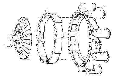
impeller
Exploded view of centrifugal compressor components
compressor drive shaft diffuser
intake air
impeller compressed air (to combustion chamber)
A centrifugal compressor slings air to the outside, compressing it into a diverging chamber known as a diffuser.
FIGURE 3.4 | Centrifugal-flow compressor.
Exploded view courtesy of United Technologies Pratt & Whitney.
Dual-axial compressor
low-pressure compressor drive shaft
spinning compressor rotor
stationary stator vanes
intake air compressor drive shaft
compressed air (to combustion chamber)
An axial-flow compressor drives air along its longitudinal axis through a progressive series of spinning rotor blades and fixed stator vanes. (By reducing rotational air movement from the spinning blades, stator vanes sustain linear airflow through the compressor and aid compression.) Air pressure increases after each “compressor stage,” consisting of one row of rotor blades and the following row of stator vanes.
FIGURE 3.5 | Axial-flow compressor.
Dual-axial compressor courtesy of United Technologies Pratt & Whitney.
turbine. The two are connected by the low-pressure compressor shaft. Rotational speed of a low-pressure compressor is known as “N1”; therefore, the lowpressure compressor shaft is also commonly called the N1 shaft.
The second compressor of a dual-compressor engine is known as the high-pressure compressor. It is driven by its own high-pressure turbine via a hollow high-pressure shaft (or N2 shaft), which counter-rotates concentrically over the N1 shaft. As you’ve probably guessed, N2 is the speed of the highpressure compressor.
To again clarify terminology, let’s describe the dual-axial compressor shown in Figure 3.5. It incorporates a nine-stage low-pressure axial compressor on one shaft, followed by a seven-stage high-pressure axial compressor on a separate shaft. The two turn separately, at different speeds.
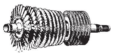
The combination of each compressor, the turbine that drives it, and the shaft connecting them is known as a spool. A glance at the separated two spools of a dual-compressor engine (Figure 3.6) shows the characteristic spool shape of each.
Core Turbine Engine (Gas Generator)
Turbine engines come in many variations. One-, two-, and three-spool models may be found, using any combination of centrifugal-flow and axial-flow compressors. In addition, any number of compressor and turbine stages may be incorporated into each spool. Such engine design details vary significantly by engine type and manufacturer. As much as these differences impact the performance and reliability of competing turbine engines, the basic arrangement and functions are the same. Every turbine engine is
Low-Pressure Spool
low-pressure compressor (4-stage axial-flow compressor shown) low-pressure turbine
low-pressure (N1) compressor shaft (turns freely inside N2 shaft)
high-pressure (N2) compressor shaft (turns freely around N1 shaft)
high-pressure compressor (1-stage centrifugal-flow compressor shown) high-pressure turbine