4 minute read
System Check Procedures


Follow the procedures below to correct the memory errors. 1. Boot from the diagnostic diskette and start the diagnostic programs. 2. Go to the diagnostic memory in the test items. 3. Press F2 in the test items. 4. Follow the instructions in the message window. NOTE: Make sure that the DIMM is correctly inserted into the connector. A wrong connection will cause errors.
Power System Check
To verify the symptoms, power on the computer by using the following power sources separately. 1. Remove the battery pack. 2. Connect the power adaptor and check the power supply. 3. Disconnect the power adaptor and install the battery pack, then check the power supply. If you think there is a power supply problem, please go to “Check the Power Adaptor” and “Check the Battery Pack” in this chapter.
Check the Power Adaptor
Unplug the power adaptor cable from the computer and measure the output voltage at the plug of the power adaptor cable. See the illustration and follow the procedures below.
pin 1: +19V to +20.5V pin 2: 0V, ground
1. If the voltage is not correct, replace the power adaptor. 2. If the voltage is within the range: (1) Replace the system board. (2) If the problem is still not resolved, see “Undetermined Problems”. (3) If the voltage is not correct, go to the next step. NOTE: An audible noise from the power adaptor does not always indicate a defect. 3. If the power-on indicator does not light up, check the power cord of the power adaptor for continuity and correct installation. 4. If the operational charge does not work, see “Check the Battery Pack”.
Check the Battery Pack
Follow the procedures below to check the battery pack. From software, this helps to identify the problem is on recharging or discharging. 1. Check the Power Management in Control Panel. 2. Then confirm that the parameters shown in the screen for Current Power Source and Total
Battery Power Remaining are correct.
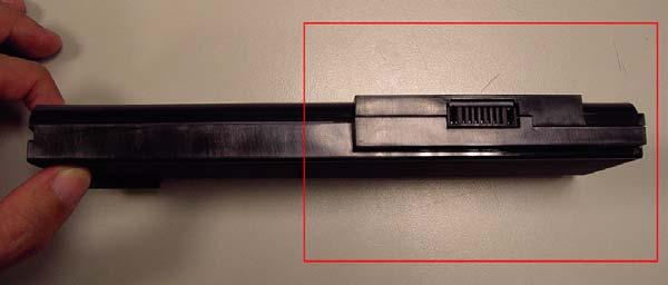
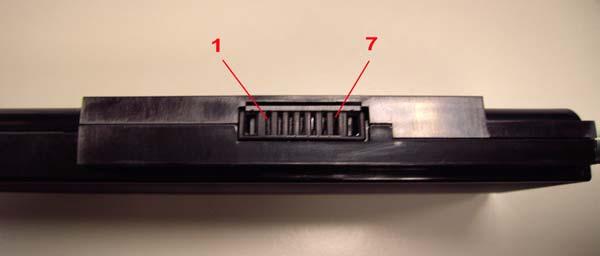
3. Repeat the step 1 and step 2 for both battery and adaptor. From hardware, this helps to identify whether you should replace the battery pack or not. 1. Power off the system. 2. Remove the battery pack and measure the voltage between terminals one (+) and seven (-).
There are seven terminals totally. See the illustration below.
3. If the voltage is still less than 7.5V after recharging, replace the battery. If the battery status indicator does not light up, remove the battery pack. After the battery pack returns to room temperature, reinstall it to the system. If the charge indicator does not light up, replace the battery pack. If the charge indicator still does not light up, replace the AC/DC charger board.
Touchpad Check
If the touchpad does not work, follow the procedures one at a time to correct the problem. Do not replace a non-defective FRU. 1. Reconnect the touchpad cables. 2. Replace the touchpad. 3. Replace the system board. After you use the touchpad, the pointer drifts on the screen for a short time. This self-acting pointer movement will occur when a slight, steady pressure is applied to the touchpad pointer. This symptom is not a hardware problem.
The POST error message index lists the error message and their possible causes.
NOTE: Perform the FRU replacement or actions in the sequence shown in Error Message List, if the FRU replacement does not solve the problem, put the original part back in the computer. Do not replace a non-defective FRU.
The error messages are listed in the coming pages to indicate the BIOS signals on the screen and the error symptoms classified by functions. If the symptom is not included on the list, please refer to “Undetermined Problems”.
NOTE: Most of the error messages occur during POST. Some of them show information about a hardware device, for example, the size of memory installed. Others may indicate problems with a device, such as the way it has been configured. NOTE: If the system fails after you make changes in the BIOS Setup Utility menus, please reset the computer. Enter Setup and install Setup defaults to correct the errors.
Index of Error Messages
Error Code List
Error Code Error Message 006 Equipment Configuration Error Causes: 1. CPU BIOS Update Code Mismatch 2. IDE Primary Channel Master Drive Error The causes will be shown before “Equipment Configuration Error”. 010 Memory Error at xxxx:xxxx:xxxxh (R: xxxxh, W: xxxxh) 070 Real Time Clock Error 071 CMOS Battery Bad 072 CMOS Checksum Error 110 System disabled. Incorrect password is specified. No error code Battery critical low: In this situation BIOS will issue four short beeps then shut down system, no message will be shown. No error code Thermal critical high: In this situation BIOS will shut down the system, no message will be shown.
Error Message List
Error Message
FRU/Action in Sequence Failure Fixed Disk Reconnect hard disk drive connector. Run “Load Default Settings” in BIOS Setup Utility. Hard disk drive System board Stuck Key see ”Keyboard or Auxiliary Input Device Check”. Keyboard error see ”Keyboard or Auxiliary Input Device Check”. Keyboard Controller Failed see ”Keyboard or Auxiliary Input Device Check”. Keyboard locked - Unlock key switch Unlock external keyboard