8 minute read
Main Unit Disassembly


Removing the Wireless Card and Memory
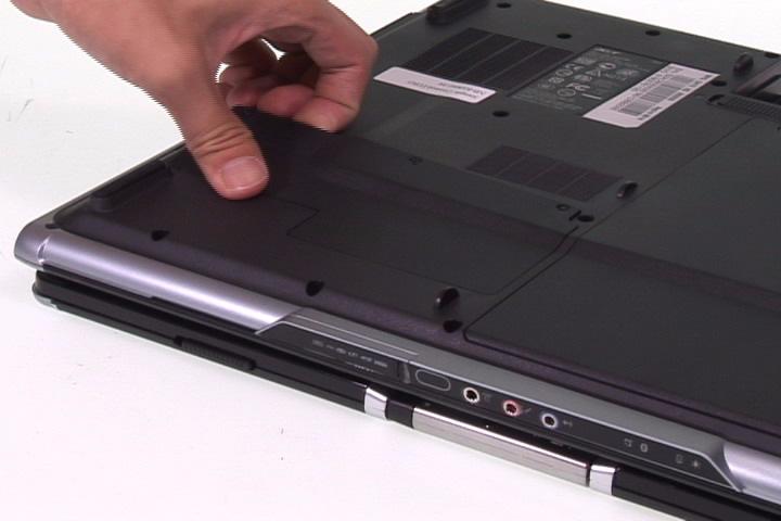
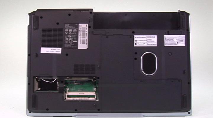
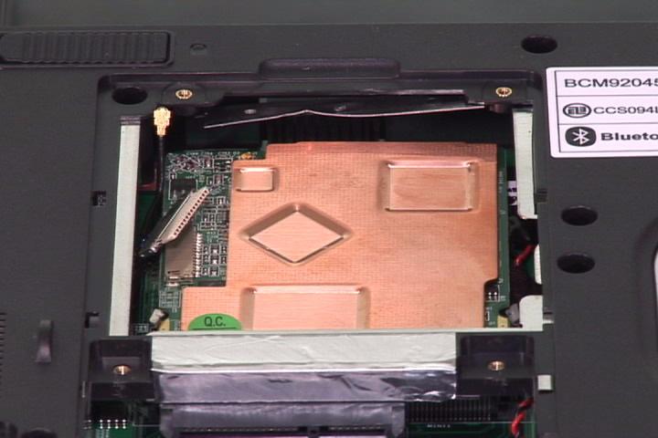
1. Remove the three screws securing the DIMM cover. 2. Remove the DIMM cover.
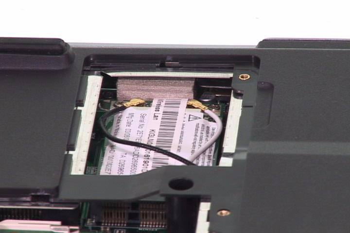
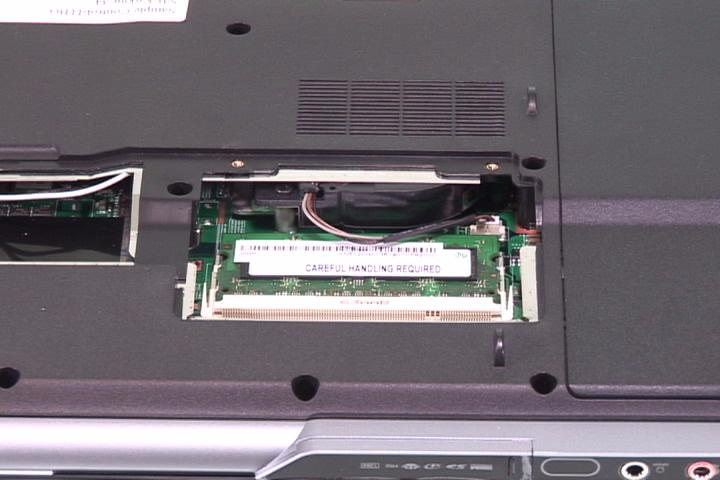
3. Disconnect the wireless antenna. 4. Remove the two screws securing the wireless card. 5. Remove the wireless card.
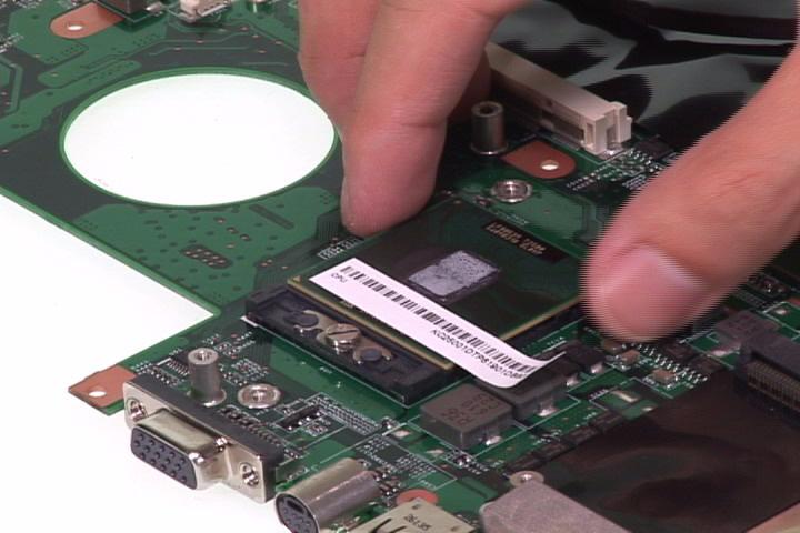
6. Press the left and right latch to pop up the DIMM2. 7. Remove the DIMM2.
8. Press the left and right latch to pop up the DIMM1.


Removing the HDD
1. Remove the four screws securing the HDD cover. 2. Remove the HDD cover.
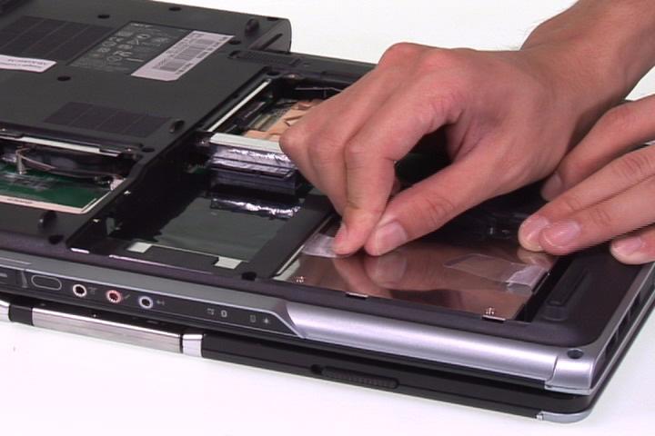
3. Remove the four screws securing the 1st and 2nd HDD. 4. Remove the 2nd HDD.


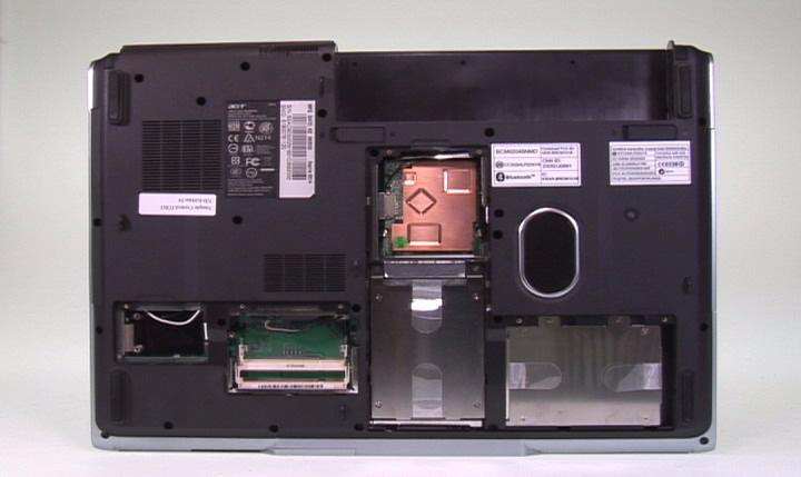
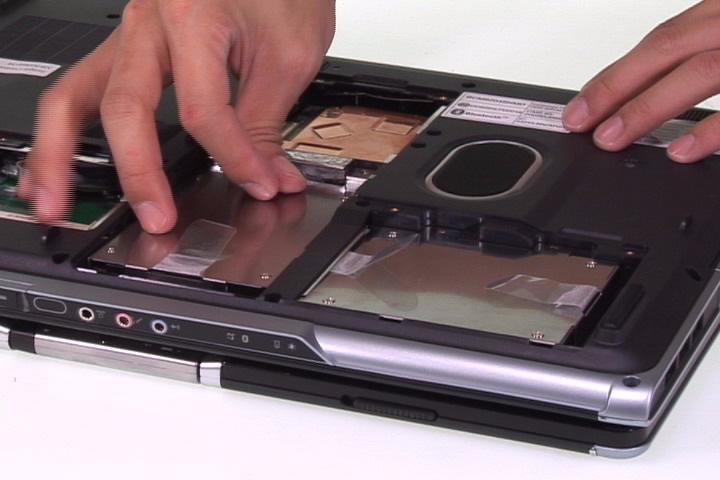
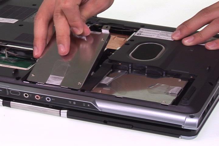
5. Remove the 1st HDD.
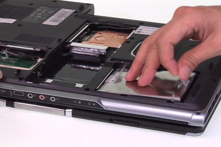
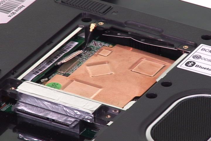
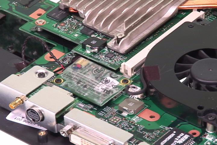
Removing the TV Card
1. Disconnect the TV card antenna. 2. Disconnect the TV card connector.


Separate the LCD Module
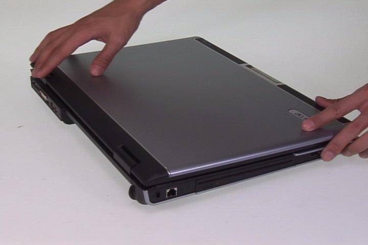
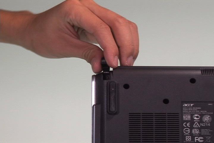
1. Press the middle cover hinge upward. 2. Open the LCD.
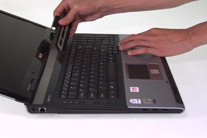
3. Remove the middle cover as shown.
4. Release the four keyboard latch and turn the keyboard over. 5. Disconnect the keyboard FFC from the mainboard. 6. Remove the keyboard.
7. Disconnec the LCD cable from the mainboard. 8. Pull the wireless antenna out as shown.
9. Remove the two screws securing the LCD hinge on the top.

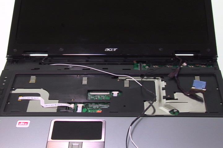
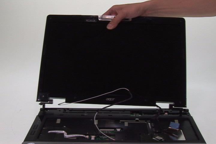
11. Remove the right and left rubber foot and remove the two screws securing the LCD hinge on the bottom. 12. Remove the LCD module from the main unit.

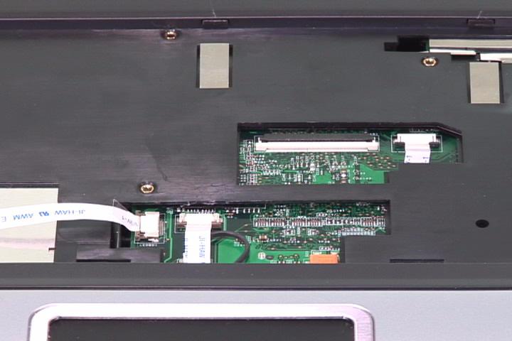
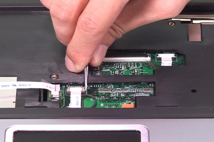
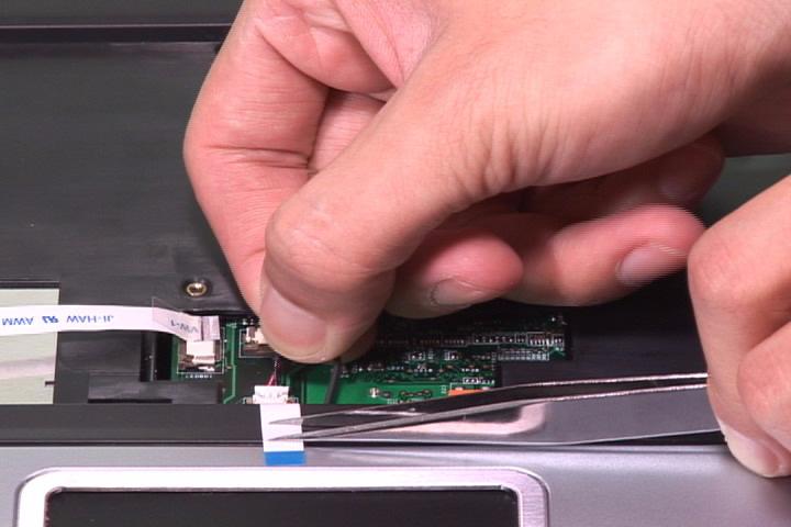
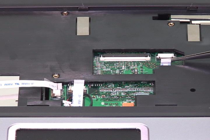
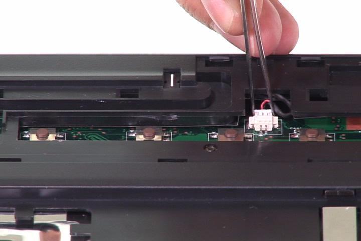
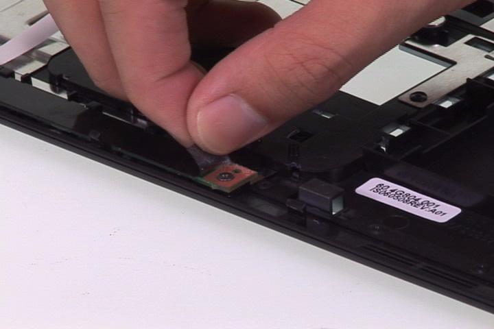
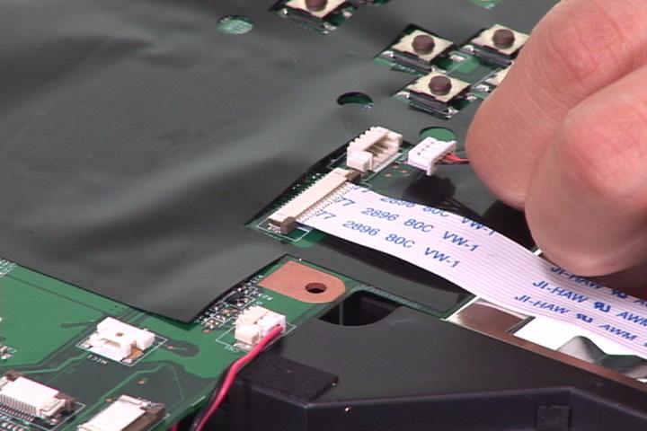
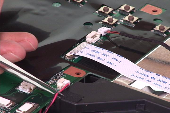
1. Disconnect the LED FFC. 2. Disconnect the touchpad FFC. 3. Disconnect the microphone cable.
4. Disconnect the media FFC from the mainboard. 5. Disconnect the lid switch cable from the mainboard.
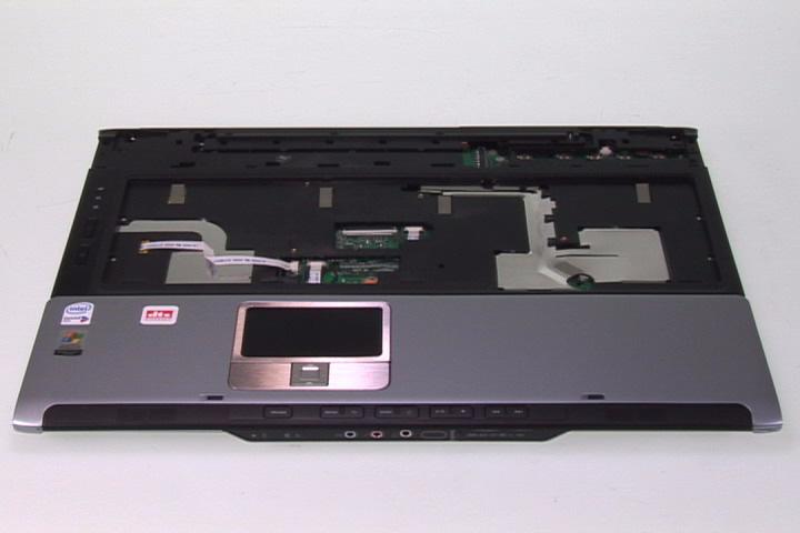
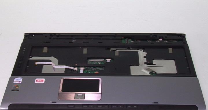
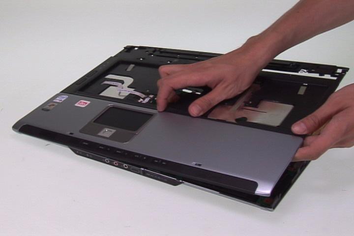
6. Remove the three screws securing the upper case.
7. Remove the 23 screws securing the lower case. 8. Separate the upper and lower case.

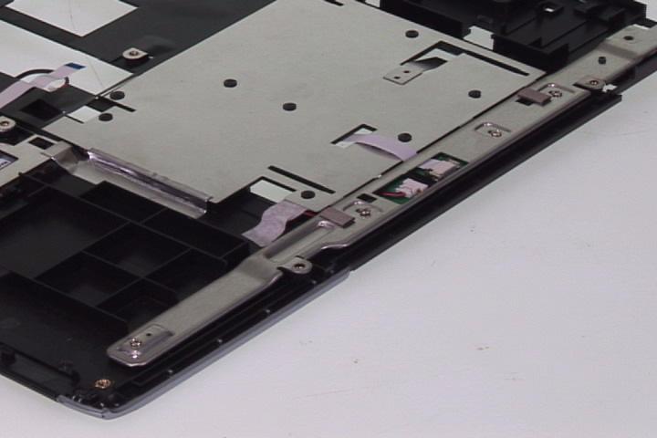
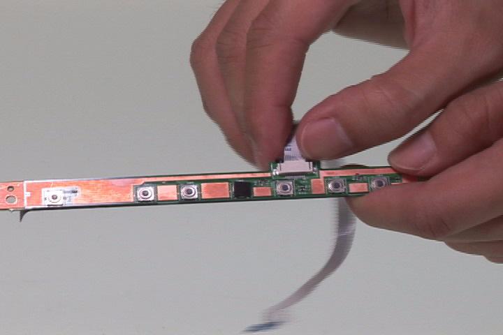
1. Remove the four screws securing the LED board bracket. 2. Remove the LED board bracket.
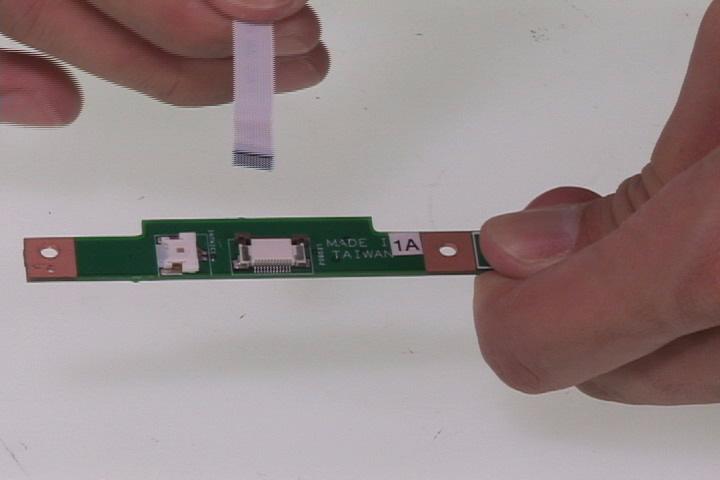
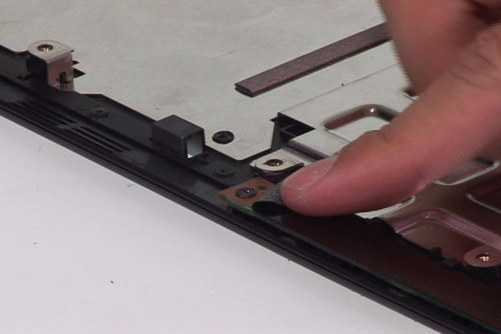
3. Disconnect the internal microphone connector. 4. Remove the LED board. 5. Disconnect the LED FFC from the LED board.
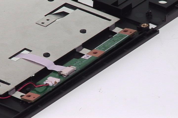
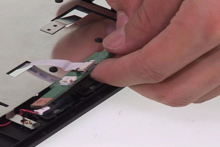
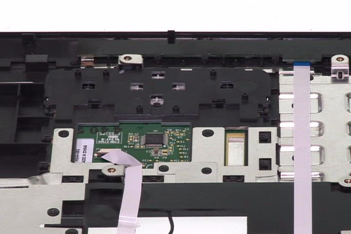
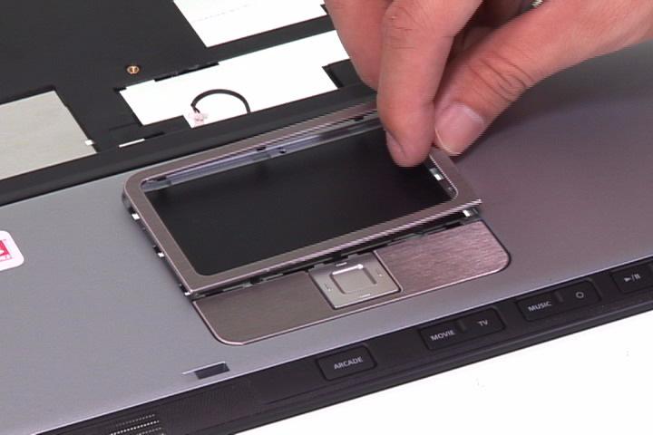
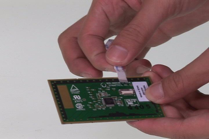
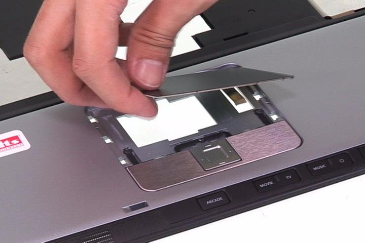
6. Release the 12 latches of the touchpad bracket. 7. Remove the touchpad bracket. 8. Remove the touchpad board.
9. Disconnect the touchpad FFC from the touchpad board.

11. Remove the media board from the upper case. 12. Disconnect the media FFC from the media board.

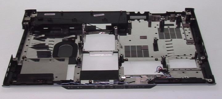
Disassemble the Lower Case
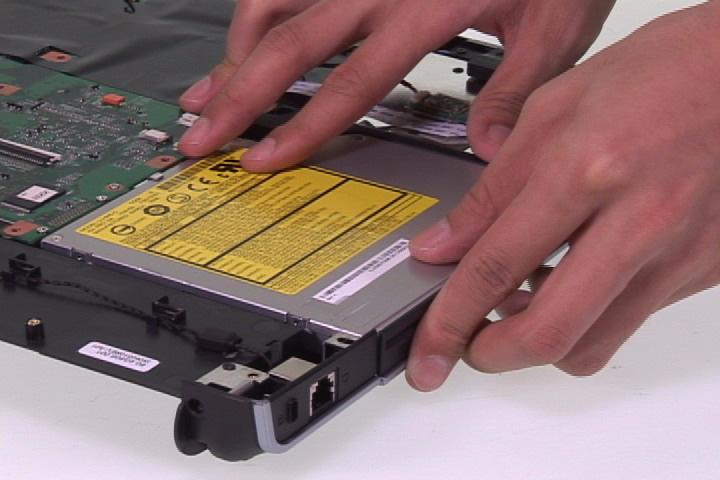
1. Remove the ODD from the main unit.
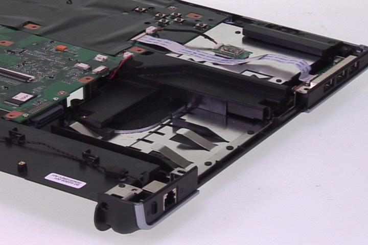
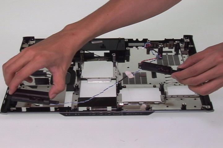
2. Disconnect the bluetooth cable from the mainboard. 3. Disconnect the USB FFC from the mainboard. 4. Disconnect the subwoofer connector from the mainboard.
5. Disconnect the speaker cable from the mainboard.
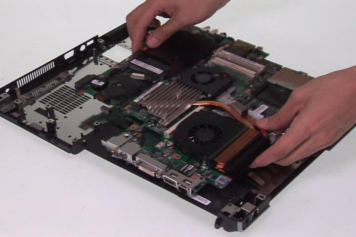
6. Remove the two screws securing the mainboard.


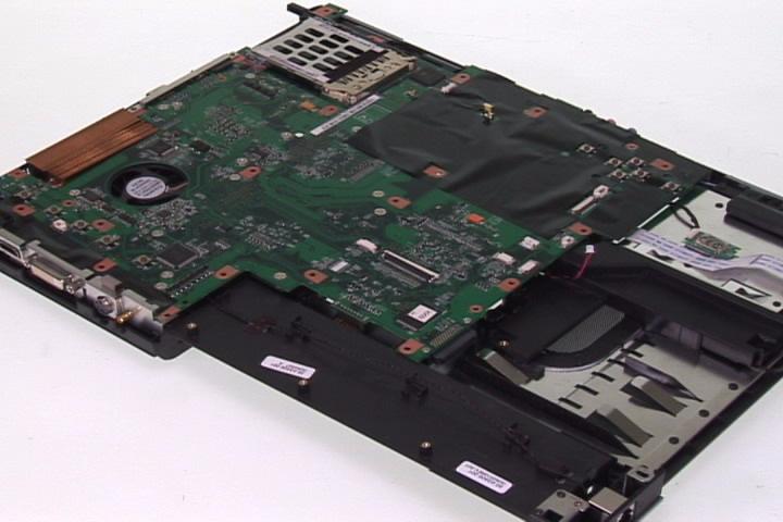
8. Remove the two screws securing the modem board. 9. Lift up the modem board, turn it over, and disconnect the modem cable from the modem board.
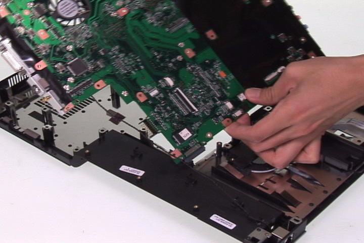
10. Remove the mainboard from the lower case.
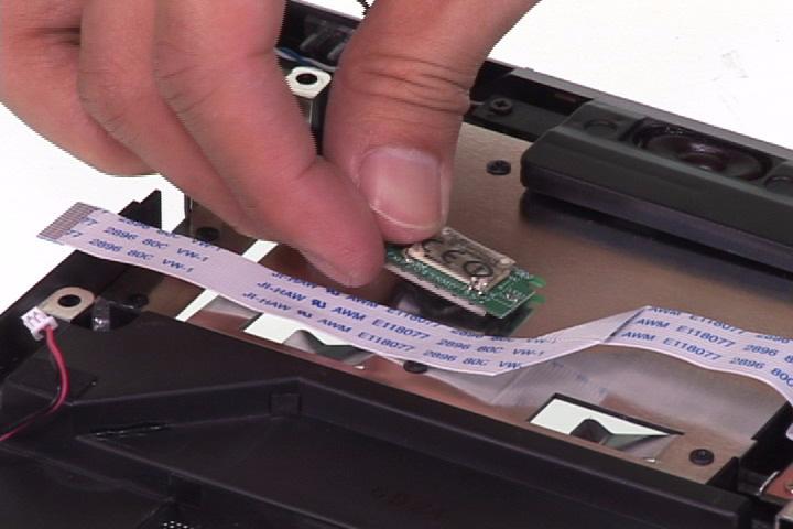
11. Remove the bluetooth module from the lower case and disconnect the bluetooth cable from the bluetooth module.

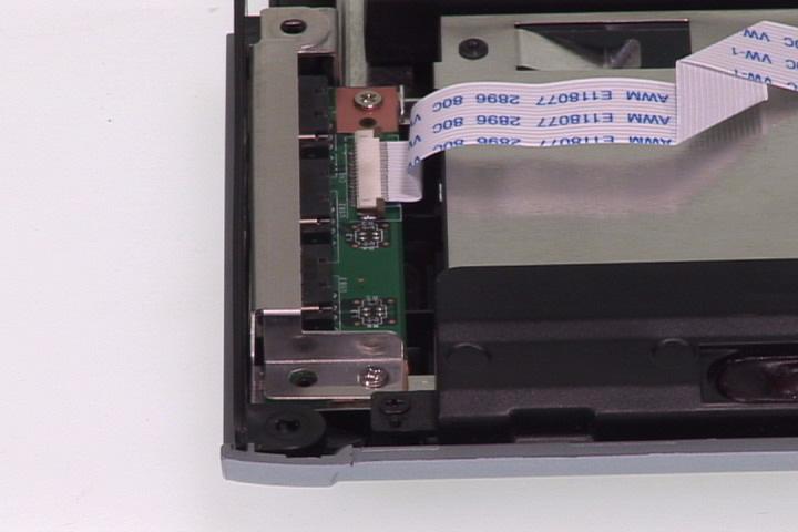
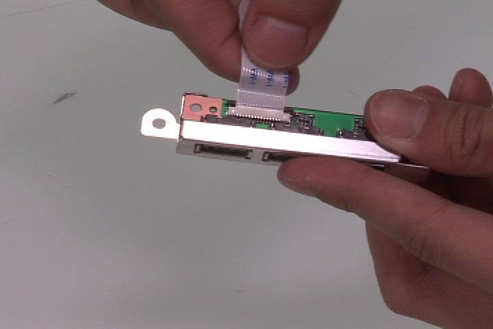
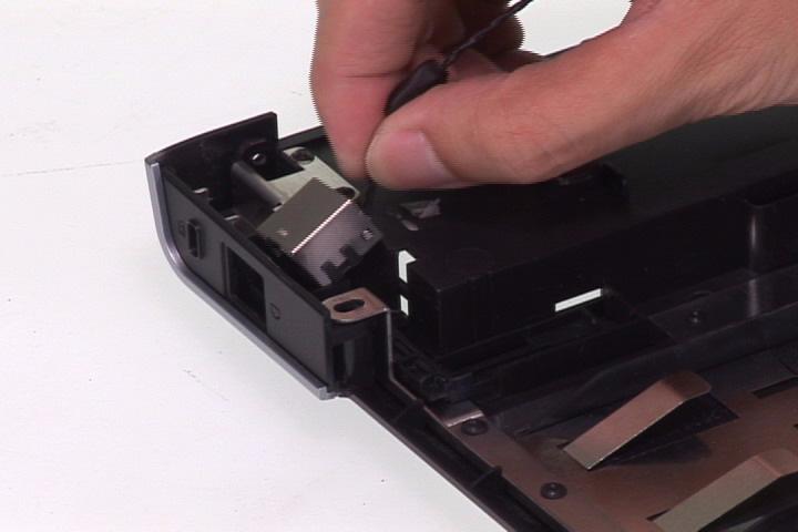
12. Remove the two screws securing the USB module. 13. Remove the USB module from the lower case. 14. Disconnect the USB FFC from the USB module.

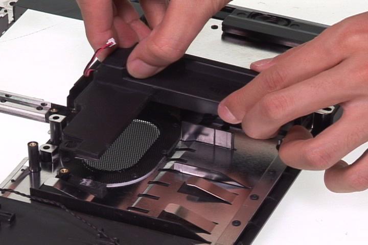
16. Remove the four screws securing the left and right speakers. 17. Remove the left and right speakers. 18. Remove the RJ11 connector from the lower case.
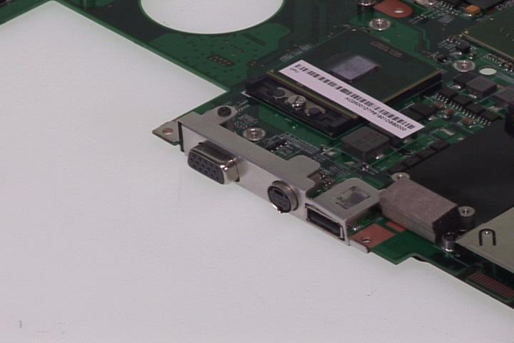
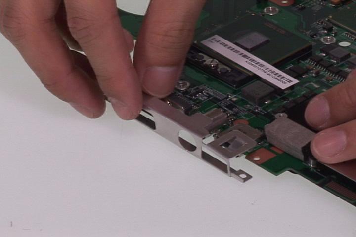
19. Remove the two screws and the two hex screws securing the I/O bracket. 20. Remove the I/O bracket from the mainboard.

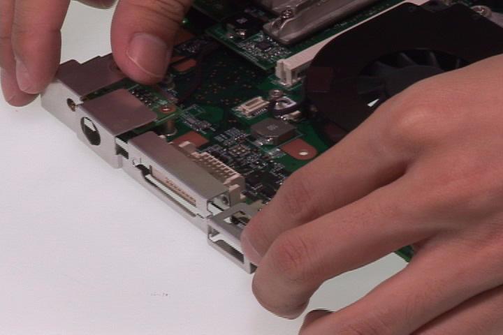
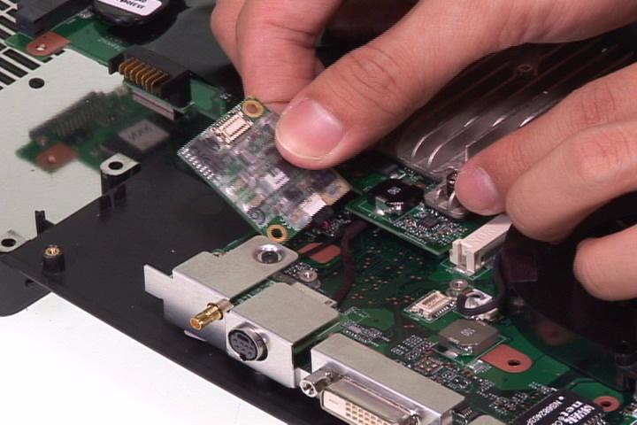
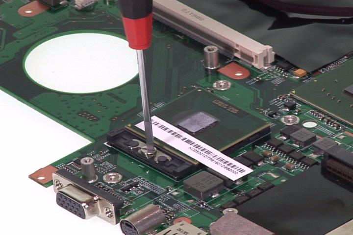
21. Remove the two screws securing the TV&RF board. 22. Turn the TV&RF board over and disconnect the TV cable and antenna.

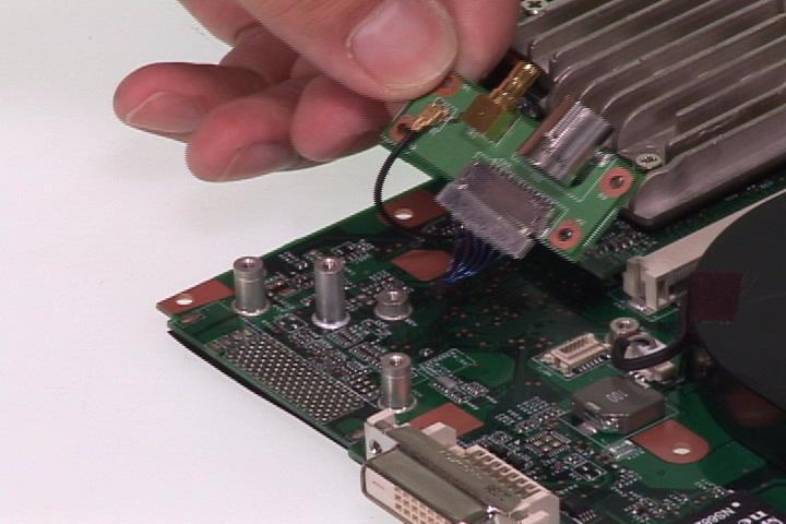
Antenna
TV cable
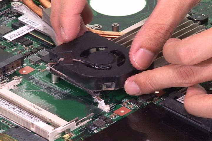
23. Remove the two screws securing the fan1. 24. Disconnect the fan1 connector from the mainboard and remove the fan1.
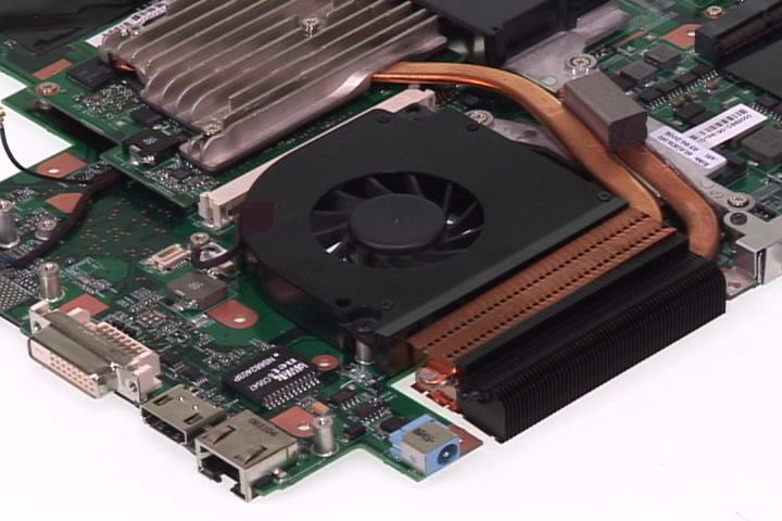


25. Remove the two screws securing the fan2. 26. Disconnect the fan2 connector from the mainboard and remove the fan2.

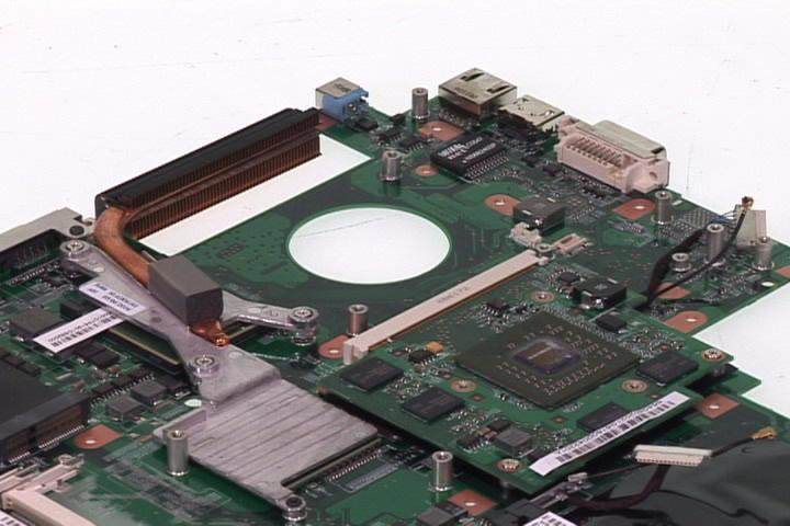
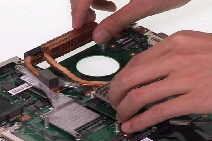
27. Release the three attached screws securing the VGA heatsink. 28. Remove the VGA heatsink.
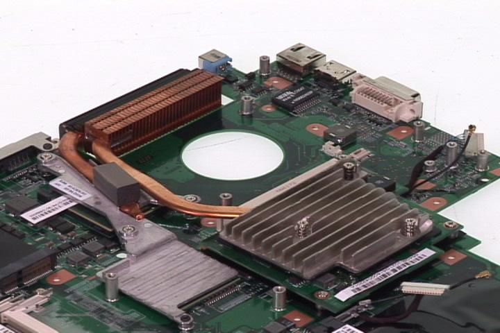
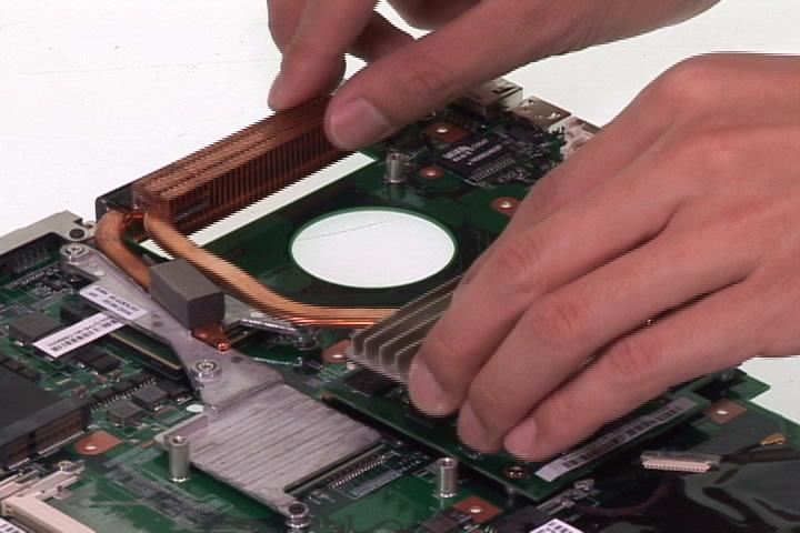
29. Remove the three attached screws and remove the screw securing the CPU heatsink. 30. Remove the CPU heatsink.
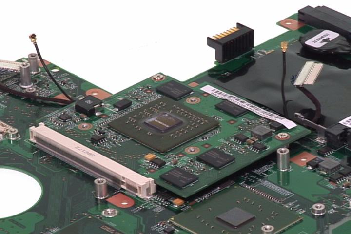
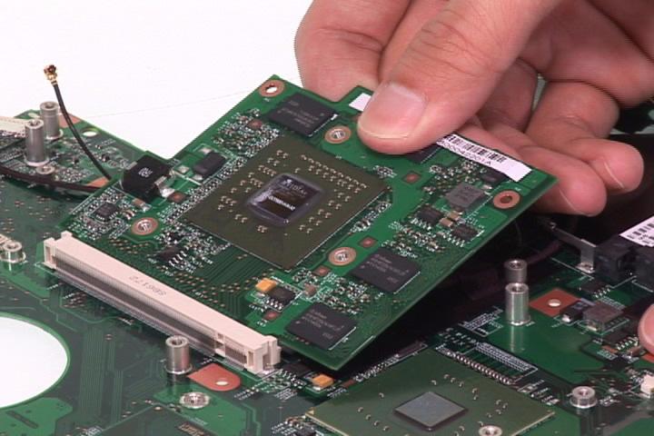
31. Remove the two screws securing the VGA card. 32. Remove the VGA card.
33. Remove the screw securing the VGA bracket. 34. Remove the VGA bracket.
37. Remove the TV cable.