48 minute read
Machine Disassembly and Replacement

from TravelMate 5710 5310 Series Extensa 5610 5210 Series Laptop Service Guide Manual - PDF DOWNLOAD

This chapter contains step-by-step procedures on how to disassemble the notebook computer for maintenance and troubleshooting.
Disassembly Requirements
To disassemble the computer, you need the following tools: ❑ Wrist grounding strap and conductive mat for preventing electrostatic discharge ❑ Flat screwdriver ❑ Philips screwdriver ❑ Hex screwdriver ❑ Plastic flat screwdriver ❑ Plastic tweezers NOTE: The screws for the different components vary in size. During the disassembly process, group the screws with the corresponding components to avoid mismatch when putting back the components.
Pre-disassembly Instructions
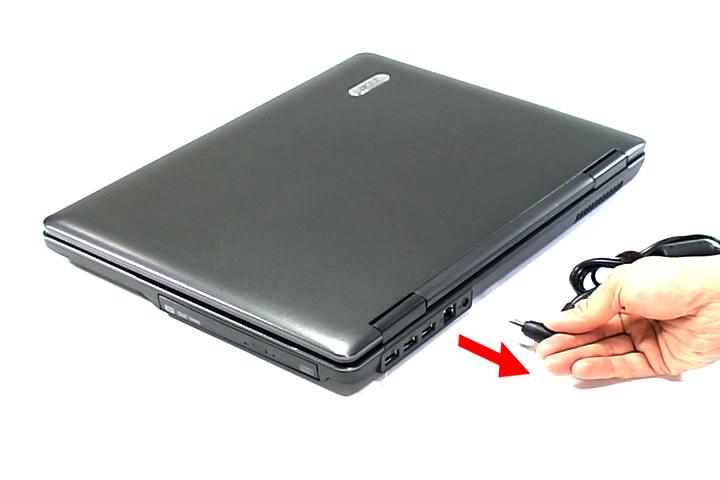
Before proceeding with the disassembly procedure, make sure that you do the following: 1. Turn off the power to the system and all peripherals. 2. Unplug the AC adapter and all power and signal cables from the system.
3. Place the system on a flat, stable surface. 4. Remove the battery pack.
Disassembly Process
The disassembly process is divided into the following stages: • External module disassembly • Main unit disassembly • LCD module disassembly The flowcharts provided in the succeeding disassembly sections illustrate the entire disassembly sequence. Observe the order of the sequence to avoid damage to any of the hardware components. For example, if you want to remove the main board, you must first remove the keyboard, then disassemble the inside assembly frame in that order.
Main Screw List
Item Screw Color Part No.
A M2.5 x L6 Black 86.00E33.736
B M2 x L4 Black 86.00A02.140
C M2 x L4 Silver 86.9A552.4R0
D M2.5 x L5 Silver 86.00E74.335
E M2.5 x L5 Black 86.00F87.735
F M2 x L3 Silver 86.00C07.220
G M2.5 x L6 Silver 86.9A544.4R0
H M2.5 x L8 Black 86.00E34.738
External Modules Disassembly Flowchart
The flowchart below gives you a graphic representation on the entire disassembly sequence and instructs you on the components that need to be removed during servicing. For example, if you want to remove the main board, you must first remove the keyboard, then disassemble the inside assembly frame in that order. EXTERNAL MODULE DISASSEMBLY
Fx2
WLAN BOARD Bx7
LOWER COVER
DIMM MODULES TURN OFF POWER AND PERIPHERALS
UNPLUG POWER CABLES
Ax1
OPTICAL DISK DRIVE MODULE
OPTICAL DISK DRIVE Cx1
OPTICAL
LOCKER
BRACKET
HDD MODULE
HARD DISK RUBBER ENCLOSURE HARD DISK DRIVE
Screw List
Screw Part No.
A M2.5 x L6 86.00E33.736 B M2 x L4 86.00A02.140 C M2 x L4 86.9A552.4R0 F M2 x L3 86.00C07.220
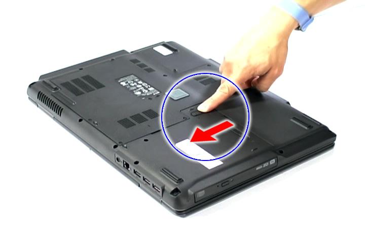
1. Turn base unit over. 2. Slide the battery lock/unlock latch to the unlock position (1).
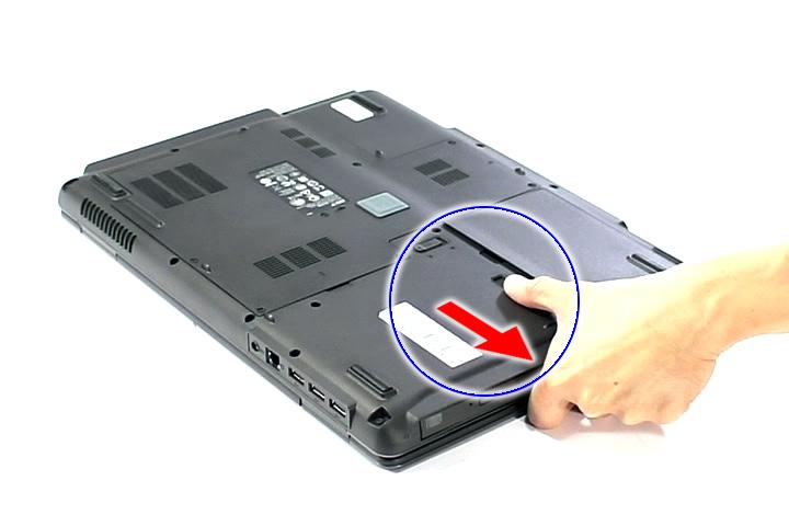
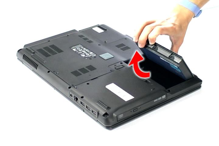
3. Slide and hold the battery release latch to the release position (2), then remove the battery from the main unit (3).
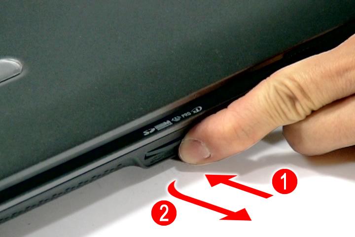
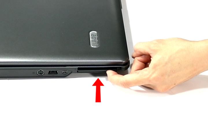
Removing the SD dummy card
1. Push the SD dummy card all the way in to eject it (1, 2).
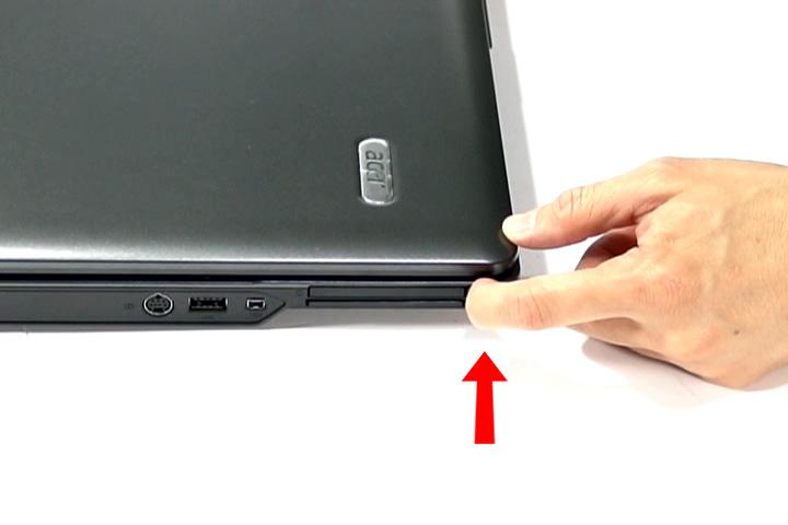
Removing the PC and ExpressCard dummy cards
1. Press the eject button to pop out the button.
2. Press it again (1) to pop out the PC dummy card (2). Remove the PC dummy card from the slot.

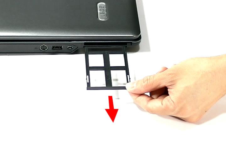
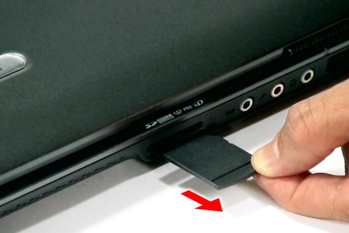
4. Pull it out from the slot.

Removing the Lower Cover
1. See “Removing the Battery Pack” on page 60. 2. See “Removing the SD dummy card” on page 60. 3. See “Removing the PC and ExpressCard dummy cards” on page 61. 4. Remove the seven screws (B) on the lower cover.
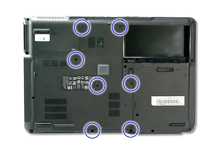
Step Size (Quantity) Color Torque
1~7 M2 x L4 (7) Black 1.6 kgf-cm
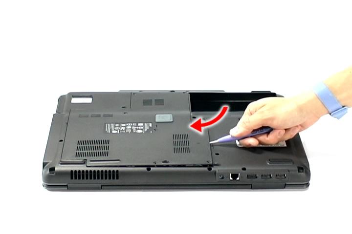
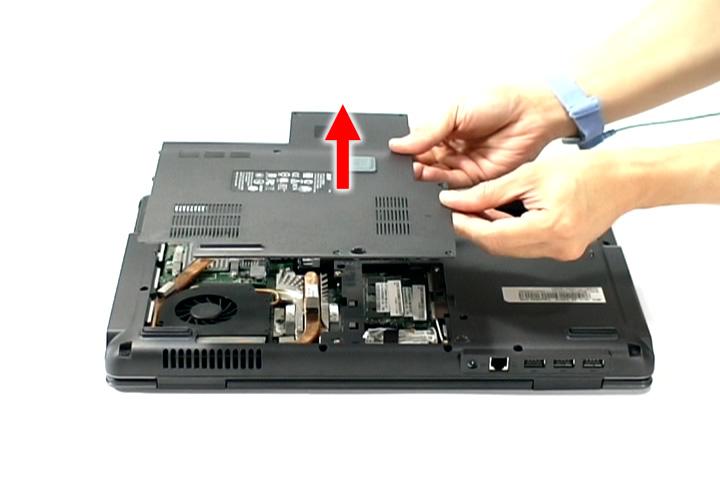
6. Remove the lower cover from the lower case.
Removing the DIMM
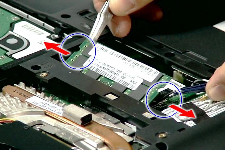
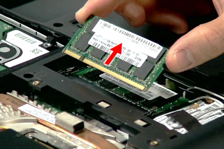
1. See “Removing the Battery Pack” on page 60. 2. See “Removing the SD dummy card” on page 60. 3. See “Removing the PC and ExpressCard dummy cards” on page 61. 4. See “Removing the Lower Cover” on page 62.. 5. Push out the latches on both sides of the DIMM socket to release the DIMM.
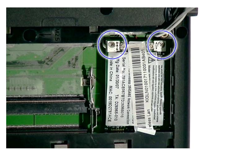
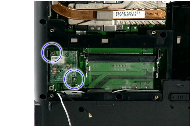
Removing the WLAN Board Modules
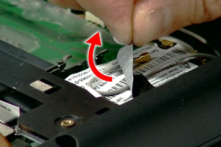
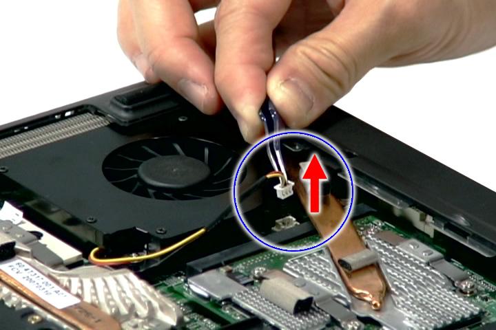
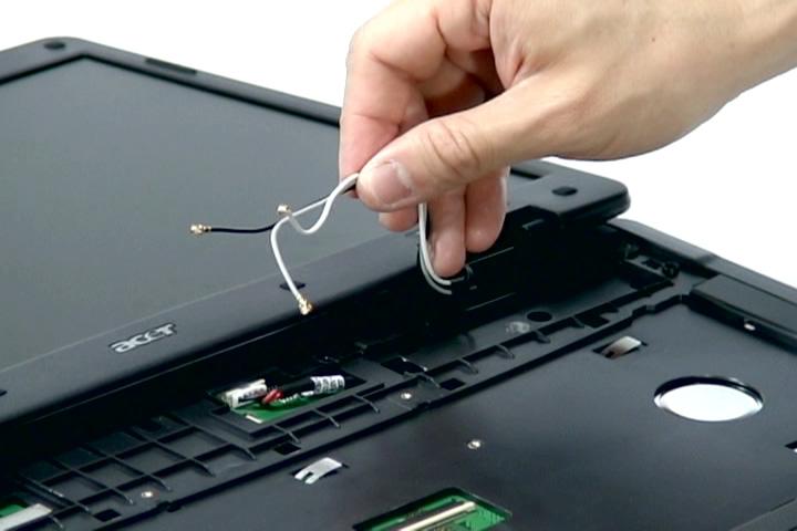
1. See “Removing the Battery Pack” on page 60. 2. See “Removing the SD dummy card” on page 60. 3. See “Removing the PC and ExpressCard dummy cards” on page 61. 4. See “Removing the Lower Cover” on page 62. 5. Remove the tape holding the gray antenna.
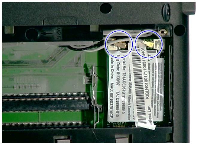
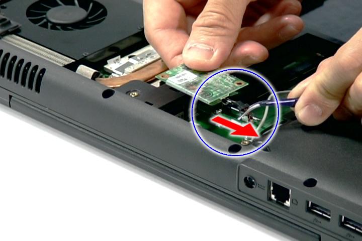
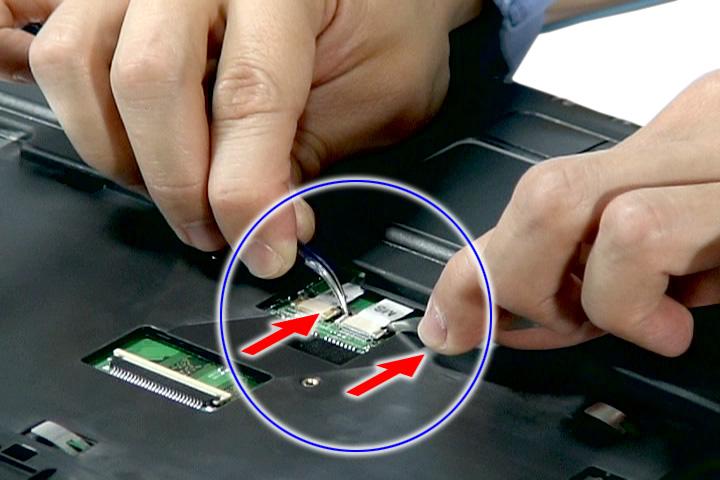
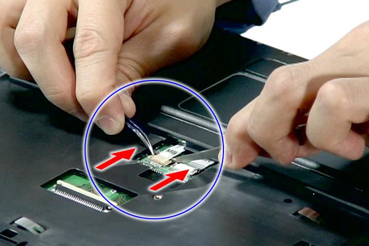
6. Disconnect the antenna cables from the WLAN board.
Step Size (Quantity) Color Torque
1~2 M2 x L3 (2) Silver 1.6 kgf-cm
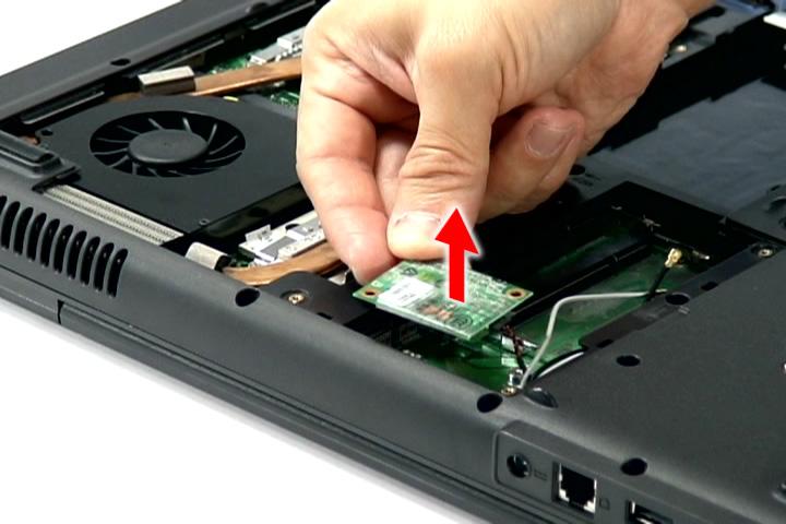
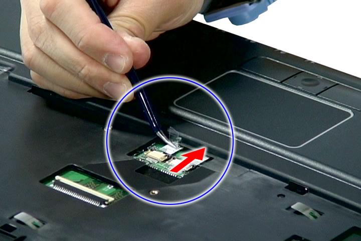
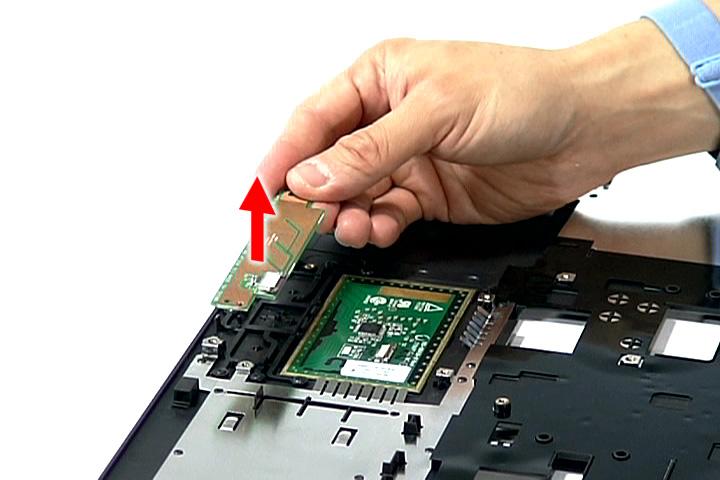
8. Detach the WLAN board from the WLAN socket.
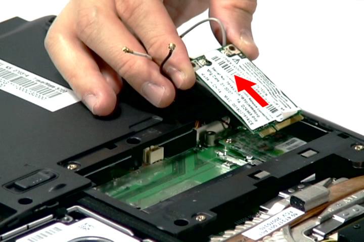
NOTE: When attaching the antenna back to the WLAN board, make sure the cable are arranged properly.
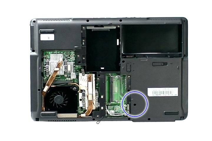
Removing the Hard Disk Drive Module
1. See “Removing the Battery Pack” on page 60. 2. See “Removing the SD dummy card” on page 60. 3. See “Removing the PC and ExpressCard dummy cards” on page 61. 4. See “Removing the Lower Cover” on page 62. 5. Remove the foam padding as shown.
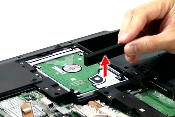
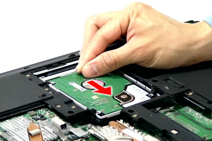
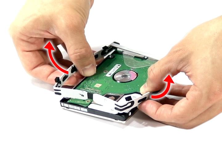
7. Remove the hard disk module.
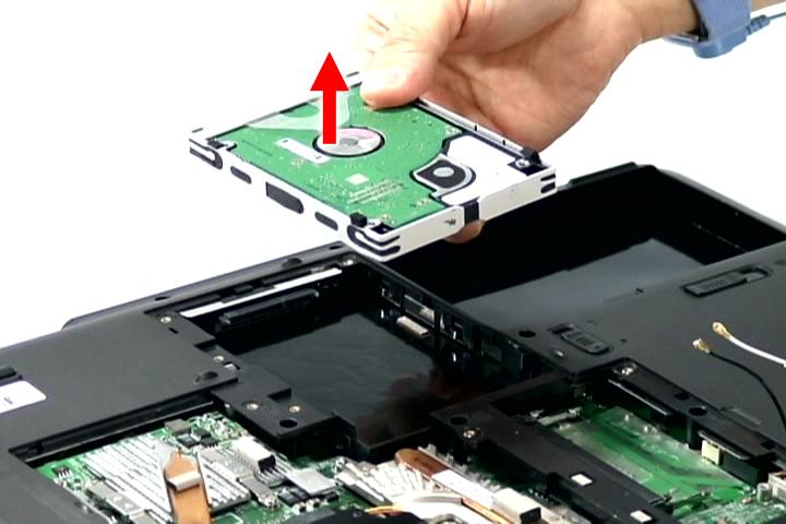
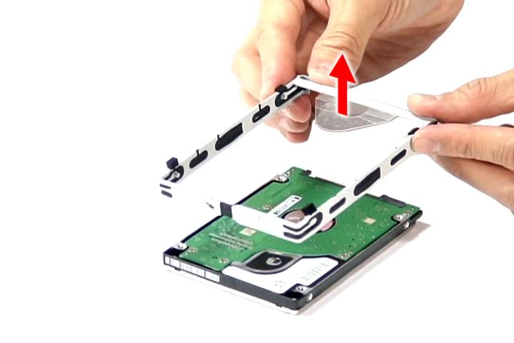
NOTE: To prevent damage to device, avoid pressing down on it or placing heavy objects on top of it. 8. Remove the hard disk from the hard disk rubber enclosure as shown.
Removing the Optical Drive Module
1. See “Removing the Battery Pack” on page 60..
Step Size (Quantity) Color Torque
1 M2.5 x L6 (1) Black 3.0 kgf-cm
3. Carefully use a plastic screw driver (1) to eject the optical drive tray (2).
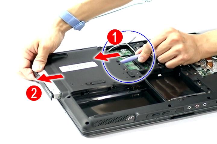
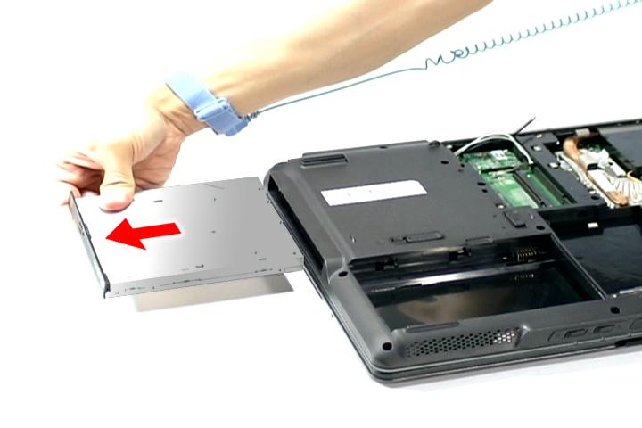
4. Pull the optical drive module out from the main unit.
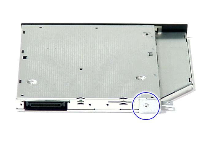
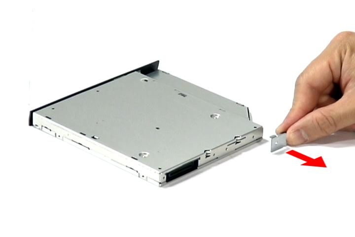
Step Size (Quantity) Color Torque
1 M2 x L4 (1) Silver 1.6 kgf-cm
Main Unit Disassembly Flowchart
MAIN UNIT DISASSEMBLY
MAIN UNIT
Cx2
HEATSINKFAN
Cx9(Cx5forUMAmodule)
CPU/VGA THERMALMODULE
CPU Dx2
VGA BOARD MIDDLE COVER Cx2
MODEM BOARD
Fx2
KEYBOARD
Ax2 Hx2
LCD MODULE Fx1
POWER BOARD
Ax14
UPPER CASE Cx2
Cx2
MAIN BOARD LAUNCHBOARD
Fx2 TOUCHPAD BRACKET ASSEMBLY
Cx1
USBBOARD Cx4
LEFTANDRIGHT SPEAKERMODULE TOUCHPAD BRACKET
TOUCHPAD BOARD Fx2 FINGERPRINT
BOARD
Screw List
Screw Part No.
A M2.5 x L6 86.00E33.736 C M2 x L4 86.9A552.4R0 D M2.5 x L5 86.00E74.335 F M2 x L3 86.00C07.220 H M2.5 x L8 86.00E34.738
1. See “Removing the Battery Pack” on page 60. 2. See “Removing the Lower Cover” on page 62. 3. See “Removing the DIMM” on page 63.. 4. See “Removing the WLAN Board Modules” on page 64.. 5. Remove the 2 screws (C) securing the modem card.
6. Lift partially to detach the modem board from the main board.
NOTE: The modem cable is still attached to the modem board.
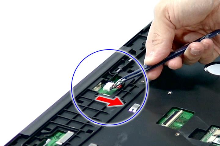
7. Disconnect the modem cable from the modem board.
Step Size (Quantity) Color Torque
1~2 M2 x L4 (2) Silver 1.8 kgf-cm
Removing the Heatsink Fan Module
1. See “Removing the Battery Pack” on page 60. 2. See “Removing the Lower Cover” on page 62.
4. Remove the two screws (C) securing the heatsink fan module.
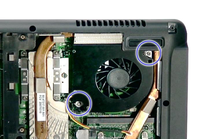
Step Size (Quantity) Color Torque
1~2 M2 x L4 (2) Silver 1.6 kgf-cm
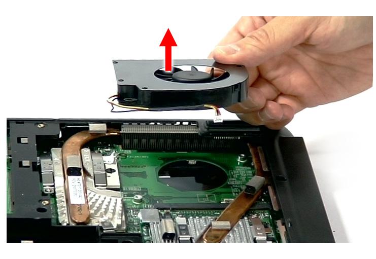
5. Remove the heatsink fan module from the main board.
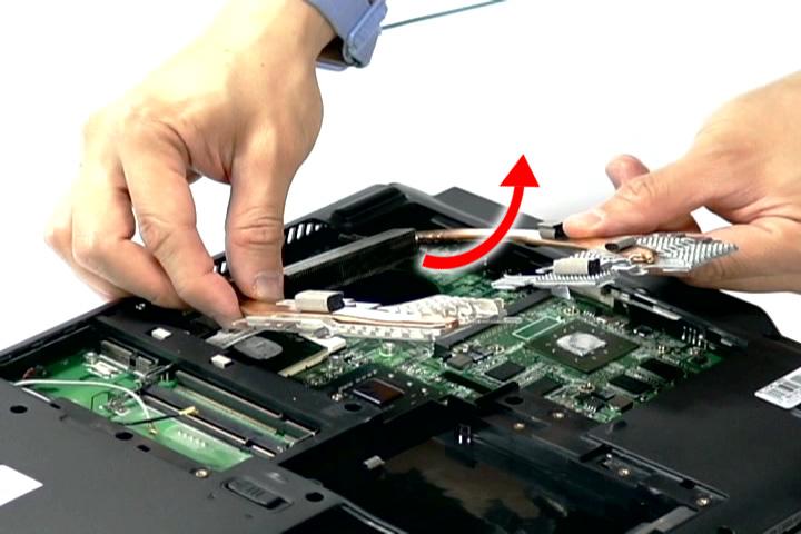
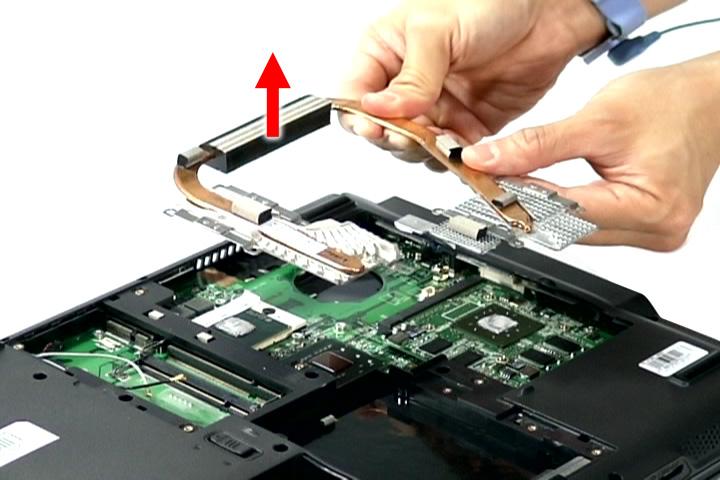
Removing the CPU and VGA Heatsink Module
1. See “Removing the Battery Pack” on page 60. 2. See “Removing the Lower Cover” on page 62.
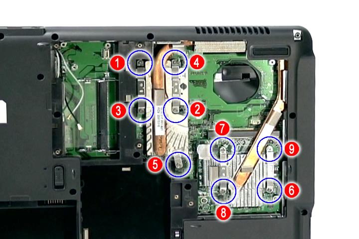
Step Size (Quantity) Color Torque
1~9 M2 x L4 (9) Silver 3.0 kgf-cm
NOTE: There are only five (5) screws for the UMA module.
4. Slide out and remove the heatsink module.
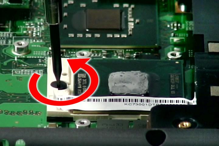
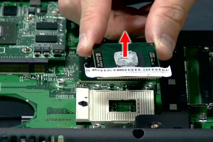
1. See “Removing the Battery Pack” on page 60.. 2. See “Removing the Lower Cover” on page 62.. 3. See “Removing the Heatsink Fan Module” on page 70. 4. See “Removing the CPU and VGA Heatsink Module” on page 71. 5. Using a flat screwdriver, turn the CPU socket latch counter-clockwise to release the CPU, then remove the CPU.
NOTE: When installing the CPU, make sure to install the CPU with PIN 1 at the corner as shown.
Removing the VGA board (for Discrete model only)
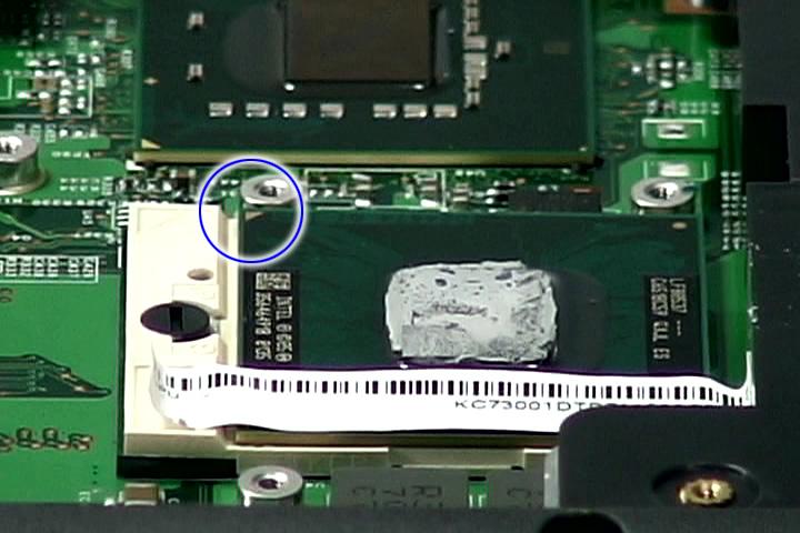
1. See “Removing the Battery Pack” on page 60. 2. See “Removing the Lower Cover” on page 62. 3. See “Removing the Heatsink Fan Module” on page 70. 4. See “Removing the CPU and VGA Heatsink Module” on page 71.
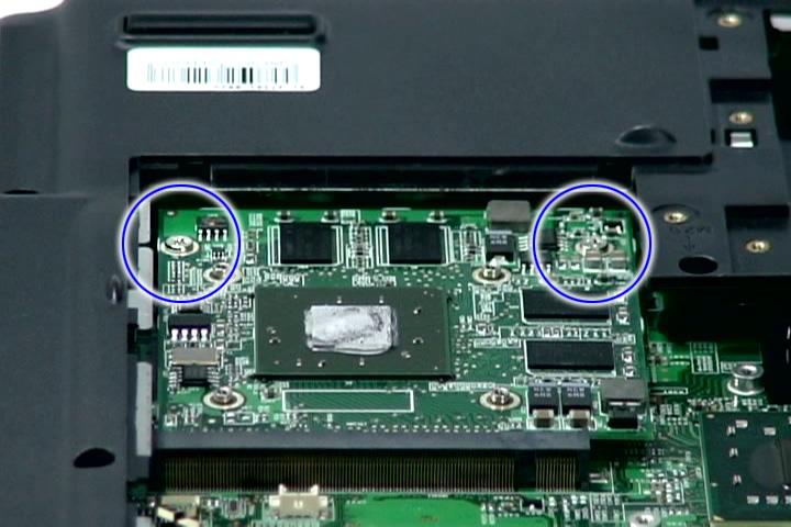
Step Size (Quantity) Color Torque
1~2 M2.5 x L5 (2) Silver 1.6 kgf-cm
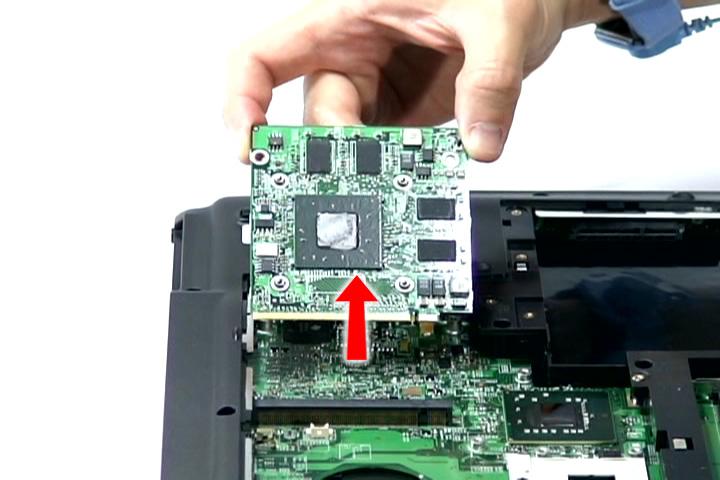
6. Carefully remove the VGA board from the main board.
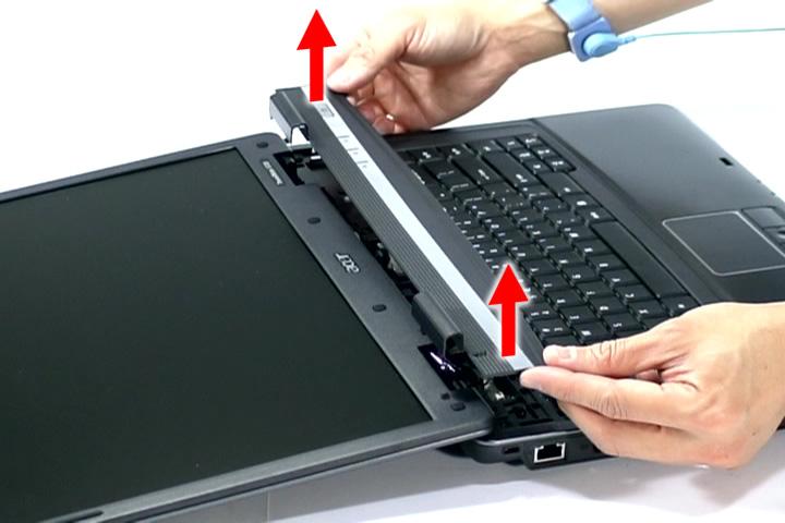
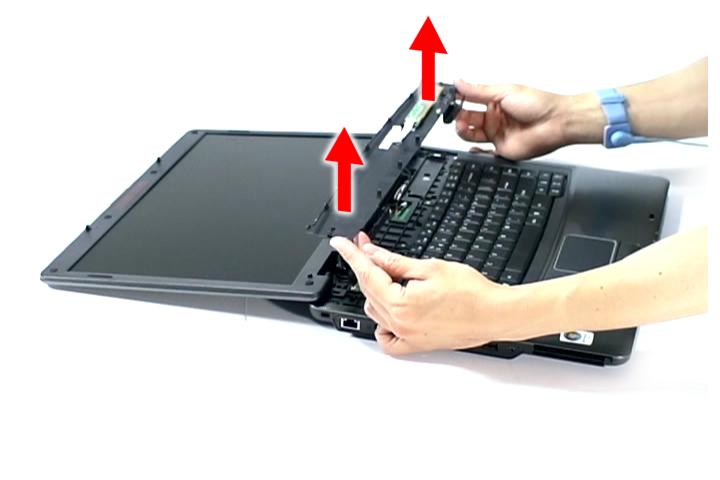
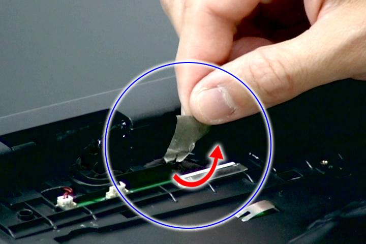
Removing the Middle Cover and the Power Board
1. See “Removing the Battery Pack” on page 60. 2. Open the LCD screen all the way to facilitate the easy removal of the middle cover. 3. To remove the Middle Cover, carefully insert the plastic flat screwdriver under the side of the middle cover and gently pry up the middle cover. Continue prying on the other side until you could detach the Middle
Cover.
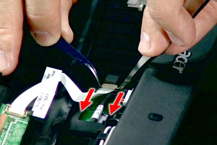
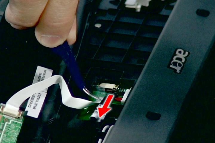
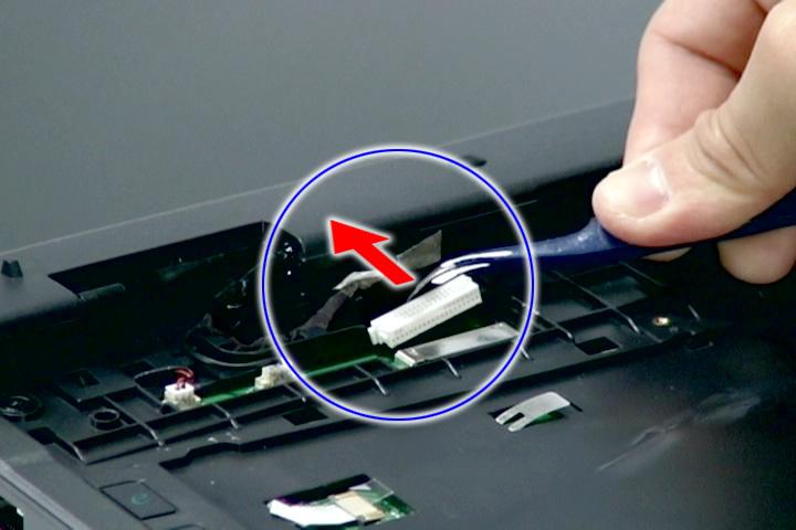
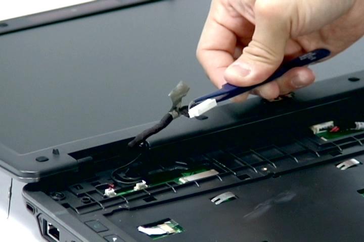
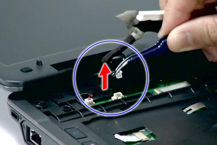
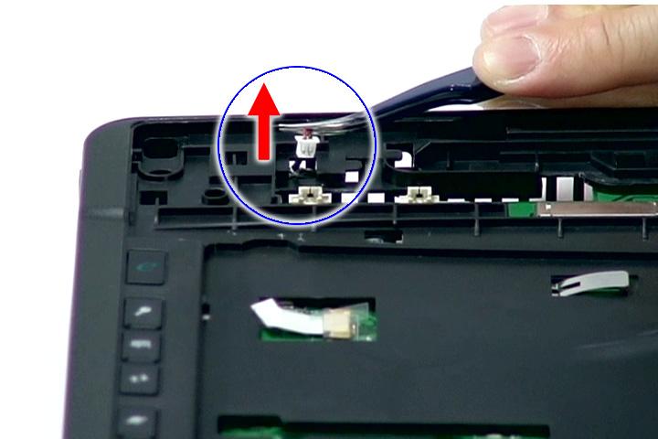
5. Disconnect the Power board cable from the main board and disconnect the Power board cable.
7. Remove the one screw (F) securing the Power board to the middle cover, and remove the Power board from the middle cover.
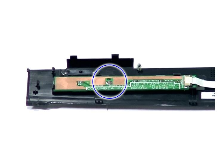
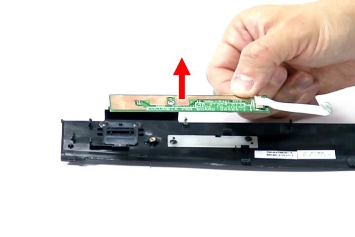
Step Size (Quantity) Color Torque
1 M2 x L3 (1) Silver 1.6 kgf-cm
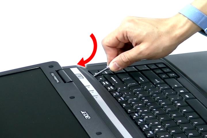
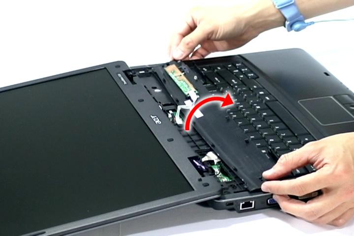
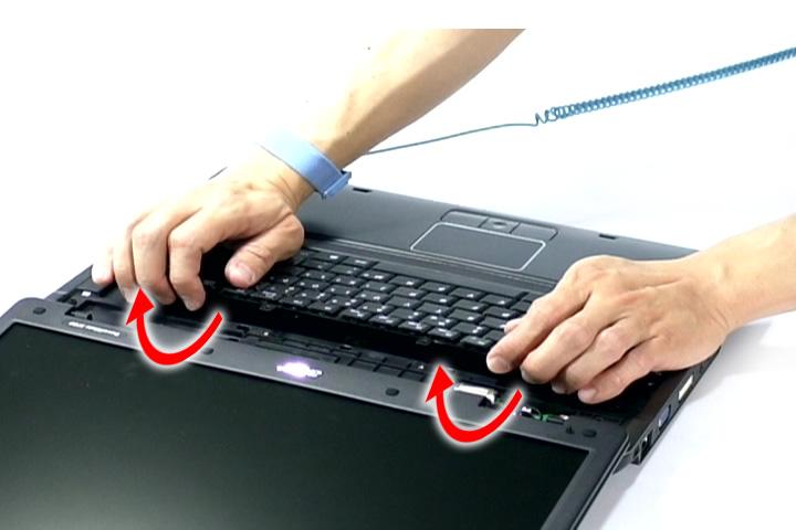
Removing the Keyboard
1. See “Removing the Battery Pack” on page 60.. 2. See “Removing the Middle Cover and the Power Board” on page 74.
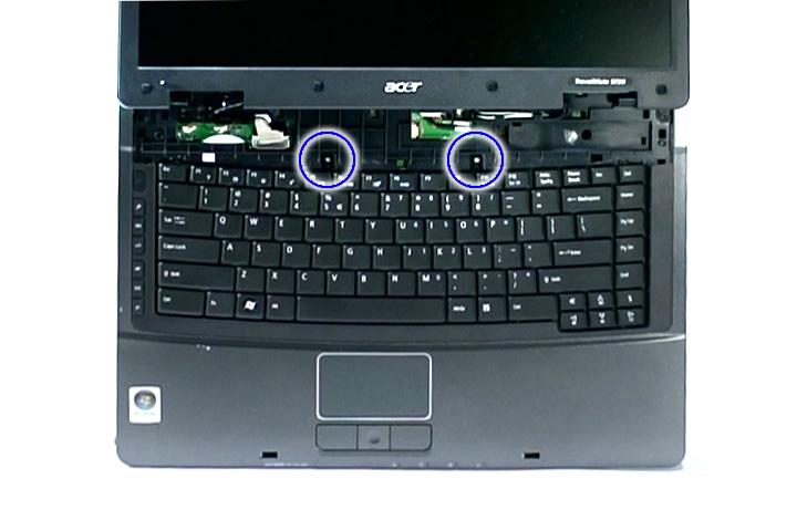
Step Size (Quantity) Color Torque
1~2 M2 x L3 (2) Silver 1.6 kgf-cm
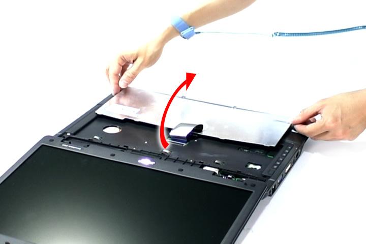
4. Carefully pry the keyboard out of the latch and slide it out; then turn it over on the touchpad area.

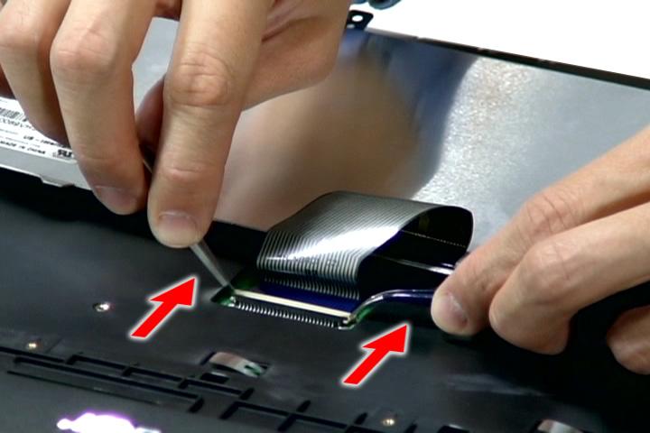
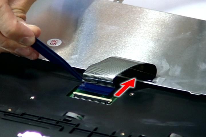
Removing the LCD Module
1. See “Removing the Battery Pack” on page 60. 2. See “Removing the Lower Cover” on page 62. 3. See “Removing the WLAN Board Modules” on page 64. 4. See “Removing the Middle Cover and the Power Board” on page 74. 5. See “Removing the Keyboard” on page 76.
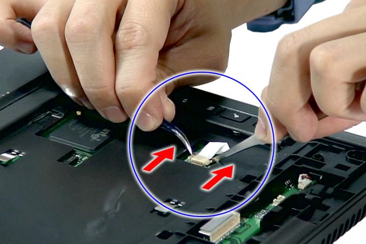
7. Remove the internal microphone cable from the INTMIC1 connector on the main board.
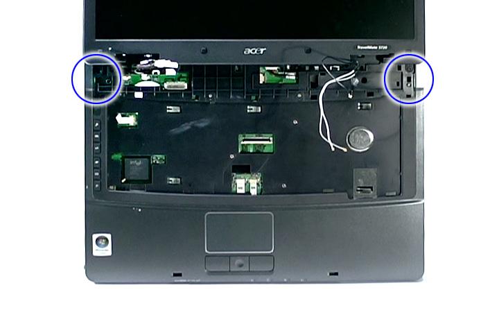
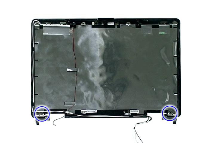
9. Remove the two screws (A) from the base of the unit.
Step Size (Quantity) Color Torque
1~2 M2.5 x L6 (2) Black 4.0 kgf-cm
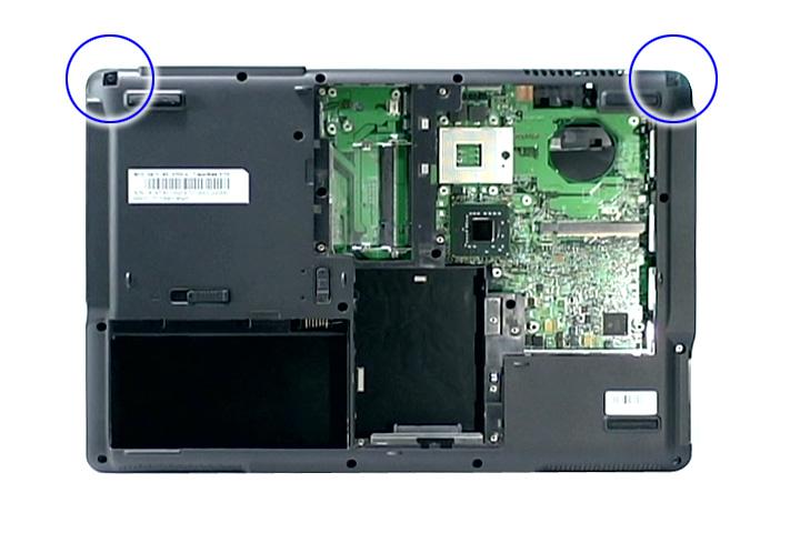
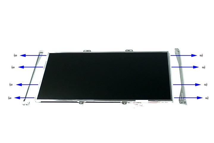
10. Remove the two screws (H) from the left and right hinge of the LCD module.
Step Size (Quantity) Color Torque
1~2 M2.5 x L8 (2) Black 4.0 kgf-cm
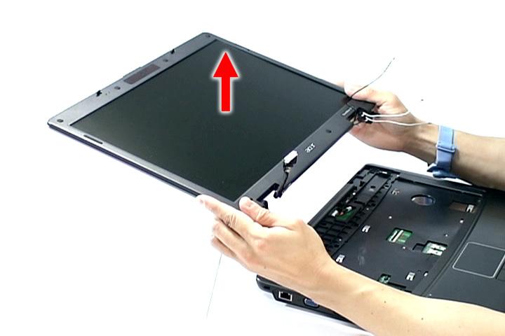
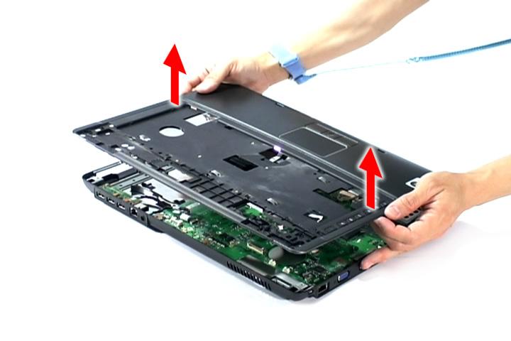
11. Carefully remove the LCD module from the base unit.
1. See “Removing the Battery Pack” on page 60. 2. See “Removing the SD dummy card” on page 60. 3. See “Removing the PC and ExpressCard dummy cards” on page 61. 4. See “Removing the Lower Cover” on page 62. 5. See “Removing the DIMM” on page 63. 6. See “Removing the WLAN Board Modules” on page 64. 7. See “Removing the Hard Disk Drive Module” on page 65. 8. See “Removing the Optical Drive Module” on page 66. 9. See “Removing the Modem Board” on page 70. 10. See “Removing the Heatsink Fan Module” on page 70. 11. See “Removing the CPU and VGA Heatsink Module” on page 71. 12. See “Removing the CPU” on page 73. 13. See “Removing the VGA board (for Discrete model only)” on page 73. 14. See “Removing the Middle Cover and the Power Board” on page 74. 15. See “Removing the Keyboard” on page 76. 16. See “Removing the LCD Module” on page 78. 17. Disconnect the cover switch cable from LID1 on the main board.
18. Disconnect the DC in cable from the main board.
20. Disconnect the fingerprint cable (select model only) from the FPCN1 connector on the main board.

22. Remove the fourteen screws (A) on the bottom panel.
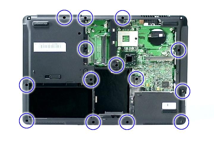
Step Size (Quantity) Color Torque
1~14 M2.5 x L6 (14) Black 3.0 kgf-cm
23. Gently raise the upper case from the main unit.
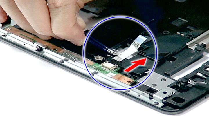
1. See “Removing the Battery Pack” on page 60. 2. See “Removing the SD dummy card” on page 60. 3. See “Removing the PC and ExpressCard dummy cards” on page 61. 4. See “Removing the Lower Cover” on page 62. 5. See “Removing the DIMM” on page 63. 6. See “Removing the WLAN Board Modules” on page 64. 7. See “Removing the Hard Disk Drive Module” on page 65. 8. See “Removing the Optical Drive Module” on page 66. 9. See “Removing the Modem Board” on page 70. 10. See “Removing the Heatsink Fan Module” on page 70. 11. See “Removing the CPU and VGA Heatsink Module” on page 71. 12. See “Removing the CPU” on page 73. 13. See “Removing the VGA board (for Discrete model only)” on page 73. 14. See “Removing the Middle Cover and the Power Board” on page 74. 15. See “Removing the Keyboard” on page 76. 16. See “Removing the LCD Module” on page 78. 17. See “Separating the Upper Case from the Lower Case” on page 81. 18. Release the latch and remove the launch board cable from the launch board.
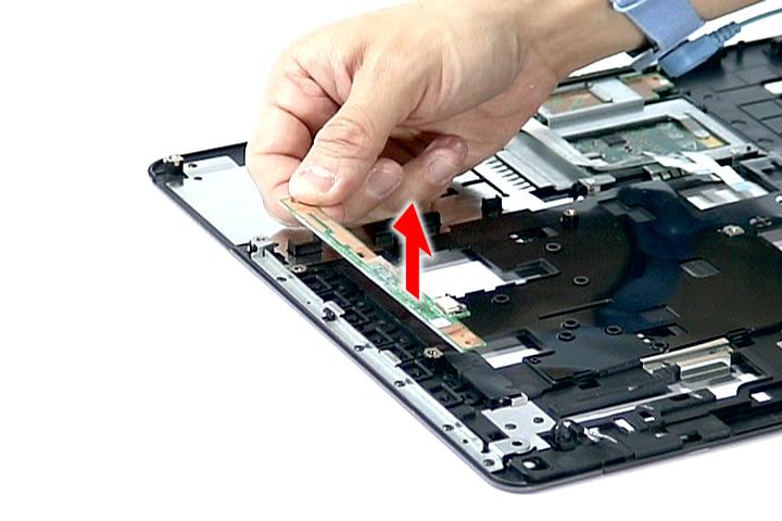
Step Size (Quantity) Color Torque
1 M2 x L3 (1) Silver 1.6 kgf-cm
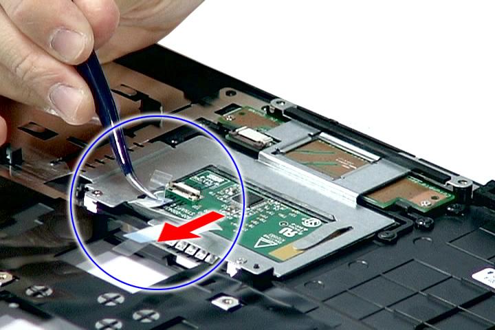
Removing theTouch Pad Board Module
1. See “Removing the Battery Pack” on page 60. 2. See “Removing the SD dummy card” on page 60. 3. See “Removing the PC and ExpressCard dummy cards” on page 61. 4. See “Removing the Lower Cover” on page 62. 5. See “Removing the DIMM” on page 63. 6. See “Removing the WLAN Board Modules” on page 64. 7. See “Removing the Hard Disk Drive Module” on page 65. 8. See “Removing the Optical Drive Module” on page 66. 9. See “Removing the Modem Board” on page 70. 10. See “Removing the Heatsink Fan Module” on page 70. 11. See “Removing the CPU and VGA Heatsink Module” on page 71. 12. See “Removing the CPU” on page 73. 13. See “Removing the VGA board (for Discrete model only)” on page 73. 14. See “Removing the Middle Cover and the Power Board” on page 74. 15. See “Removing the Keyboard” on page 76. 16. See “Removing the LCD Module” on page 78. 17. See “Separating the Upper Case from the Lower Case” on page 81.
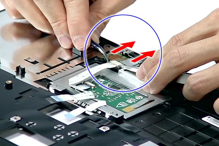
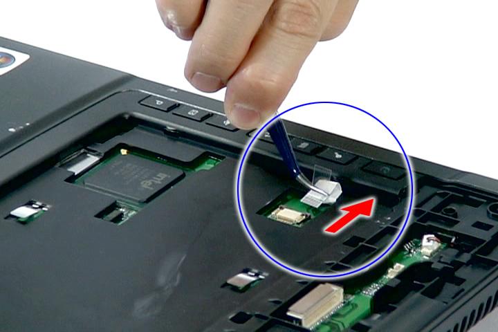
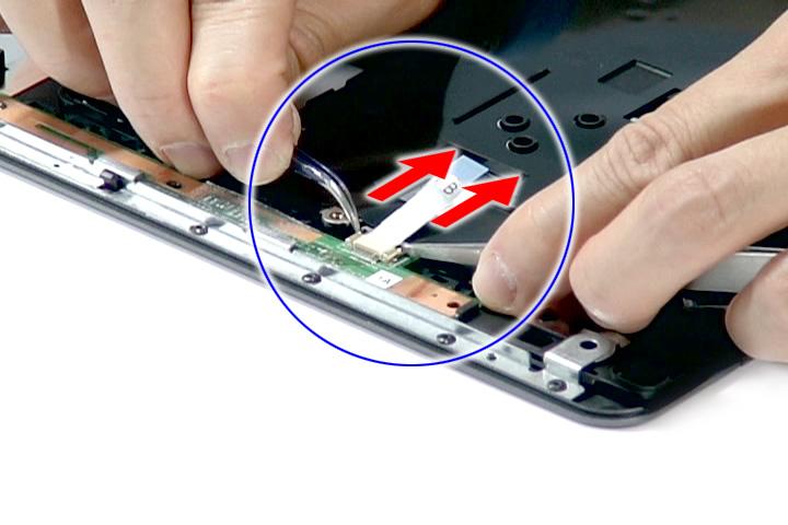
19. Remove the touch pad cable from the touch pad board.
Step Size (Quantity) Color Torque
1~2 M2 x L3 (2) Silver 1.6 kgf-cm
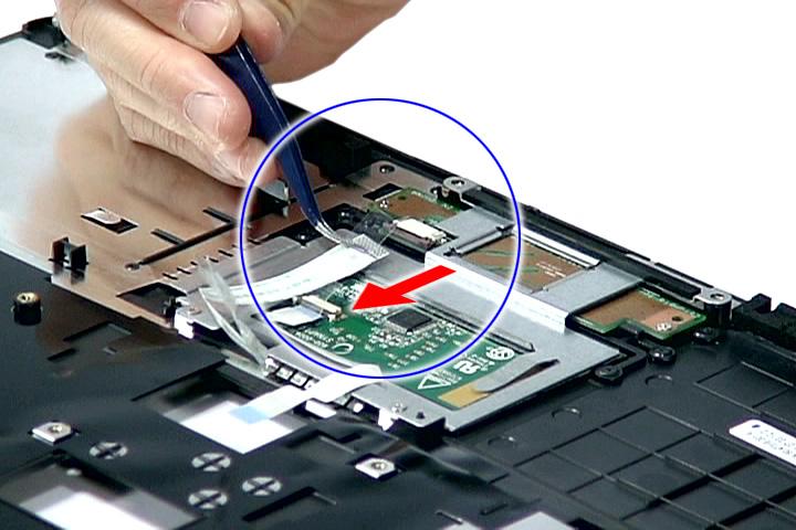
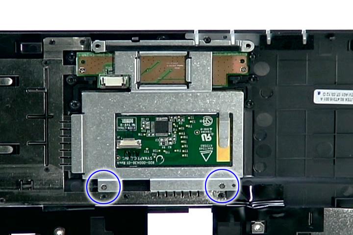
21. Remove the two screws (F) from the fingerprint board.
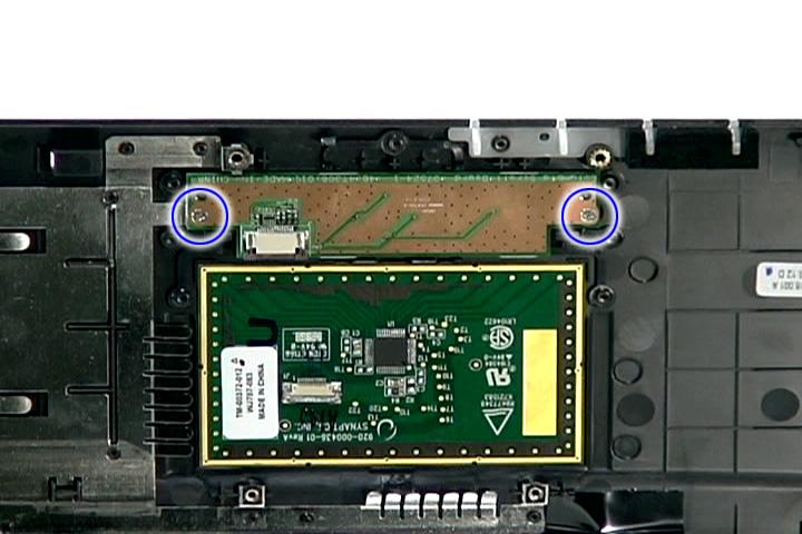
Step Size (Quantity) Color Torque
1~2 M2 x L3 (2) Silver 1.6 kgf-cm
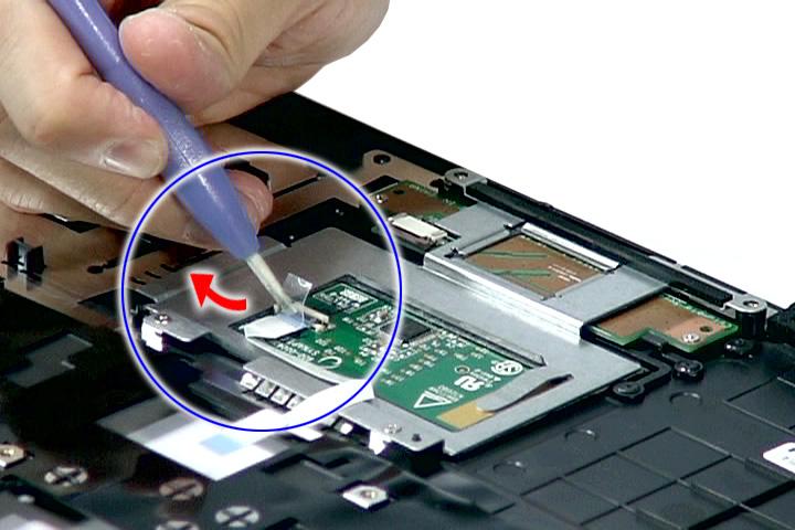
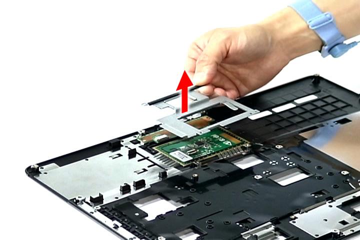
22. Remove the fingerprint board from the upper case.
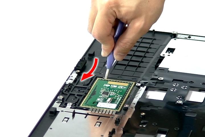
WARNING:The touchpad board is glued to the upper case, only remove the touchpad board if it is defective.
Removing the main board
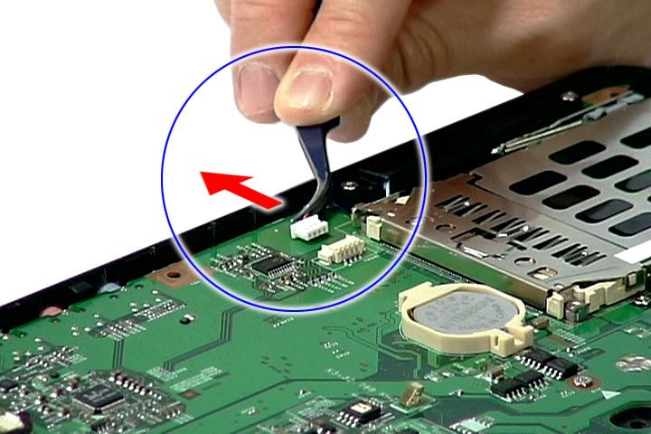
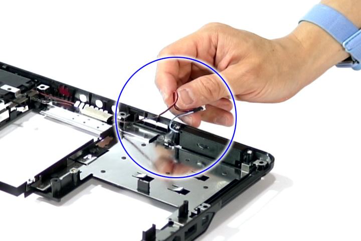
1. See “Removing the Battery Pack” on page 60. 2. See “Removing the SD dummy card” on page 60. 3. See “Removing the PC and ExpressCard dummy cards” on page 61. 4. See “Removing the Lower Cover” on page 62. 5. See “Removing the DIMM” on page 63. 6. See “Removing the WLAN Board Modules” on page 64. 7. See “Removing the Hard Disk Drive Module” on page 65. 8. See “Removing the Optical Drive Module” on page 66. 9. See “Removing the Modem Board” on page 70. 10. See “Removing the Heatsink Fan Module” on page 70. 11. See “Removing the CPU and VGA Heatsink Module” on page 71. 12. See “Removing the CPU” on page 73. 13. See “Removing the VGA board (for Discrete model only)” on page 73. 14. See “Removing the Middle Cover and the Power Board” on page 74. 15. See “Removing the Keyboard” on page 76. 16. See “Removing the LCD Module” on page 78. 17. See “Separating the Upper Case from the Lower Case” on page 81. 18. Disconnect the Bluetooth cable from the BLUE1 connector on the main board.
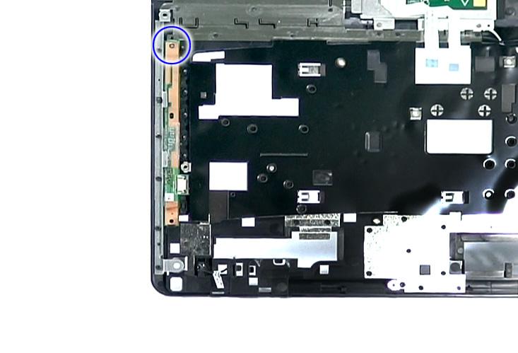
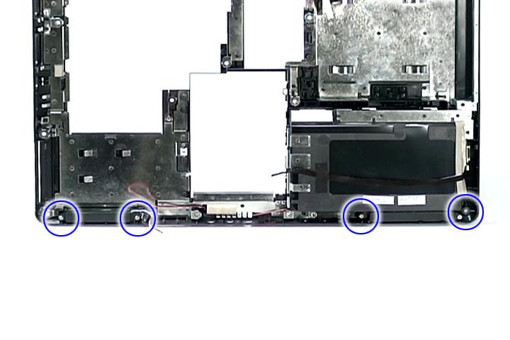
20. Remove the two screws (C) holding the main board.
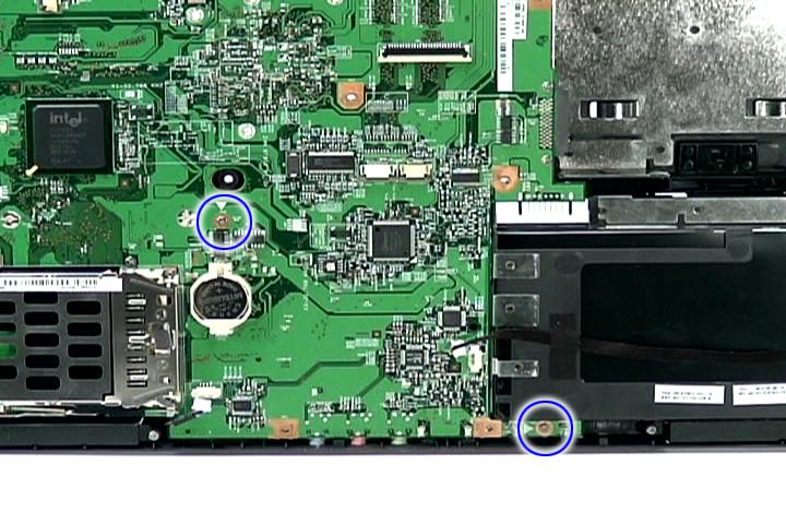
Step Size (Quantity) Color Torque
1~2 M2 x L4 (2) Silver 1.6 kgf-cm
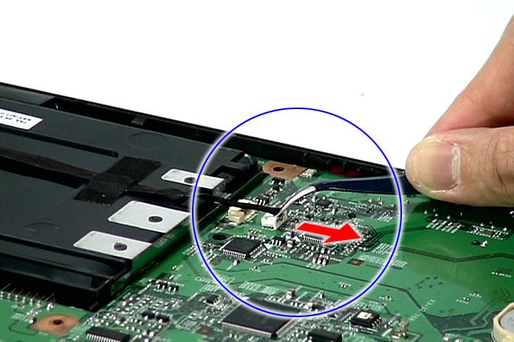
21. Carefully detach the main board and turn it over to access the USB board cable.
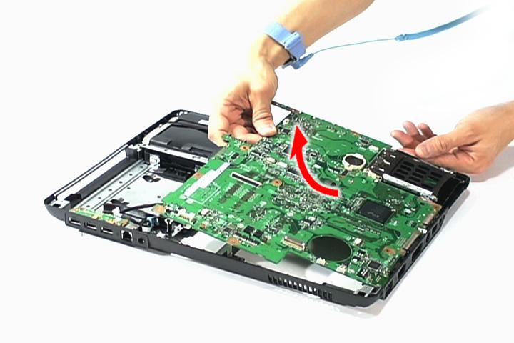
22. Detach the USB board cable from the USBCN1 on the main board.
1. See “Removing the Battery Pack” on page 60. 2. See “Removing the SD dummy card” on page 60. 3. See “Removing the PC and ExpressCard dummy cards” on page 61. 4. See “Removing the Lower Cover” on page 62. 5. See “Removing the DIMM” on page 63. 6. See “Removing the WLAN Board Modules” on page 64. 7. See “Removing the Hard Disk Drive Module” on page 65. 8. See “Removing the Optical Drive Module” on page 66. 9. See “Removing the Modem Board” on page 70. 10. See “Removing the Heatsink Fan Module” on page 70. 11. See “Removing the CPU and VGA Heatsink Module” on page 71. 12. See “Removing the CPU” on page 73. 13. See “Removing the VGA board (for Discrete model only)” on page 73. 14. See “Removing the Middle Cover and the Power Board” on page 74. 15. See “Removing the Keyboard” on page 76. 16. See “Removing the LCD Module” on page 78. 17. See “Separating the Upper Case from the Lower Case” on page 81. 18. See “Removing the main board” on page 88. 19. Remove the tape securing the speaker cables in place.
20. Release the speaker cables from the latches.
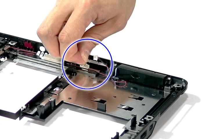
Step Size (Quantity) Color Torque
1~4 M2 x L4 (4) Silver 1.6 kgf-cm
22. Remove the left and right speakers from the upper case.

Removing the USB Board
1. See “Removing the Battery Pack” on page 60. 2. See “Removing the SD dummy card” on page 60. 3. See “Removing the PC and ExpressCard dummy cards” on page 61. 4. See “Removing the Lower Cover” on page 62. 5. See “Removing the DIMM” on page 63. 6. See “Removing the WLAN Board Modules” on page 64. 7. See “Removing the Hard Disk Drive Module” on page 65. 8. See “Removing the Optical Drive Module” on page 66. 9. See “Removing the Modem Board” on page 70. 10. See “Removing the Heatsink Fan Module” on page 70. 11. See “Removing the CPU and VGA Heatsink Module” on page 71. 12. See “Removing the CPU” on page 73. 13. See “Removing the VGA board (for Discrete model only)” on page 73. 14. See “Removing the Middle Cover and the Power Board” on page 74. 15. See “Removing the Keyboard” on page 76. 16. See “Removing the LCD Module” on page 78. 17. See “Separating the Upper Case from the Lower Case” on page 81. 18. See “Removing the main board” on page 88.
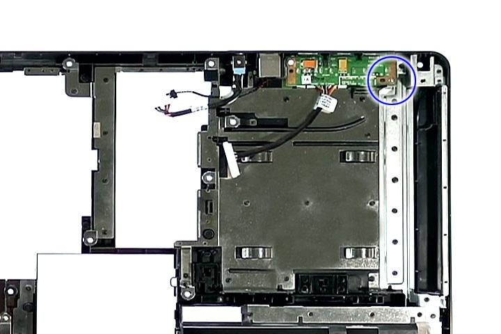
Step Size (Quantity) Color Torque
1 M2 x L4 (1) Silver 1.6 kgf-cm
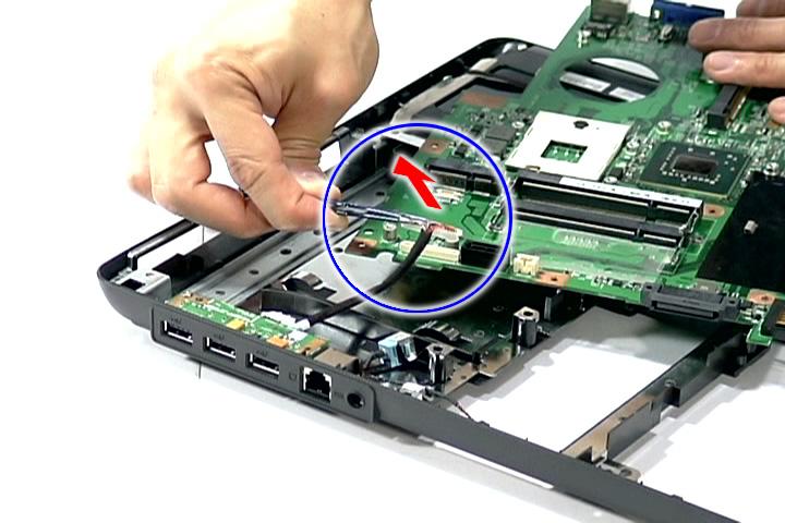
20. Partially lift the USB Board from the lower case.
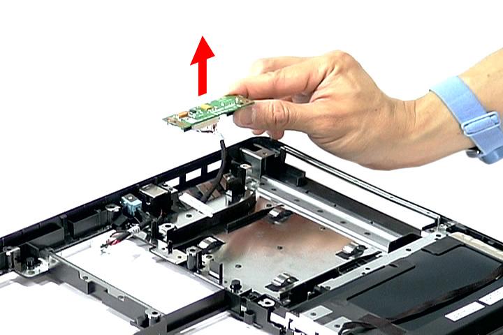
21. Detach the cable from the USB board.

LCD Module Disassembly Flowchart
LCD MODULE DISASSEMBLY
LCDMODULE
Ax8
LCDBEZEL
Ex2
LCD ASSEMBLY Ex1
INVERTER BOARD
LCD FPC CABLE Fx4
LEFT LCD BRACKET Fx4
RIGHT LCD BRACKET Ex1 Ex1
LEFT HINGE RIGHT HINGE
LCD BACK PANEL
ANTENNAS
INTERNAL MICROPHONE
Main Screw List
Item Screw Part No.
A M2.5 x L6 86.00E33.736
E M2.5 x L5 86.00F87.735
F M2 x L3 86.00C07.220
VGA CAMERA
1. See “Removing the Battery Pack” on page 60. 2. See “Removing the Lower Cover” on page 62. 3. See “Removing the DIMM” on page 63. 4. See “Removing the WLAN Board Modules” on page 64. 5. See “Removing the Middle Cover and the Power Board” on page 74. 6. See “Removing the Keyboard” on page 76. 7. See “Removing the LCD Module” on page 78. 8. Remove the four upper bezel screw caps and the four lower bezel caps.
9. Remove the eight screws (A) on the LCD module in the order as shown.
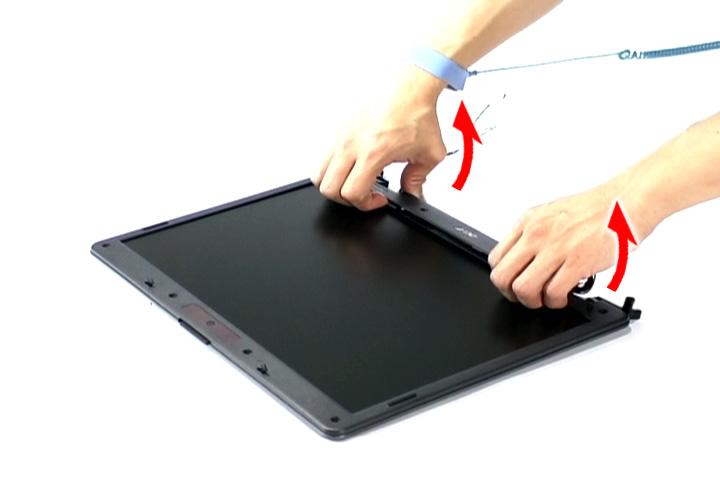
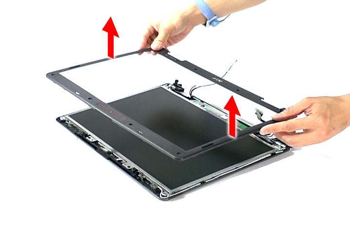
10. Carefully pry open the LCD bezel and remove the bezel from the LCD module.
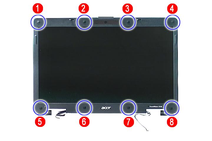
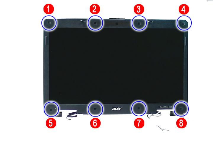
Step Size (Quantity) Color Torque
1~8 M2.5 x L6 (8) Black 3.0 kgf-cm
1. See “Removing the Battery Pack” on page 60. 2. See “Removing the Lower Cover” on page 62. 3. See “Removing the DIMM” on page 63. 4. See “Removing the WLAN Board Modules” on page 64. 5. See “Removing the Middle Cover and the Power Board” on page 74. 6. See “Removing the Keyboard” on page 76. 7. See “Removing the LCD Module” on page 78. 8. See “Removing the LCD Bezel” on page 94. 9. Disconnect the cable from the camera board.
10. Remove the three screws (E) securing the LCD module and the Inverter panel.
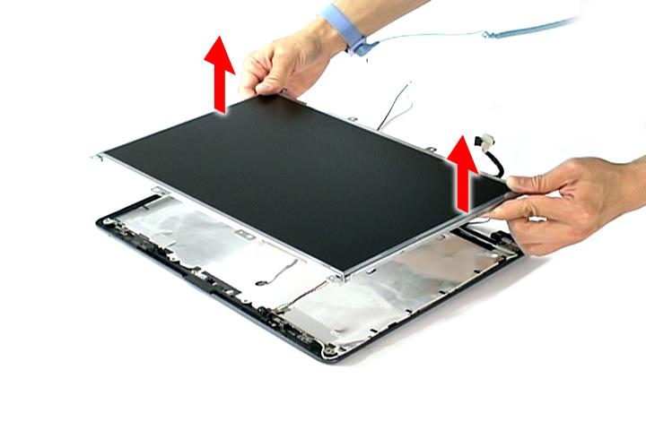
11. Detach the LCD with the brackets from the back cover.
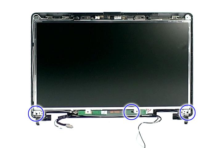
Step Size (Quantity) Color Torque
1~3 M2.5 x L5 (3) Silver 2.5 kgf-cm
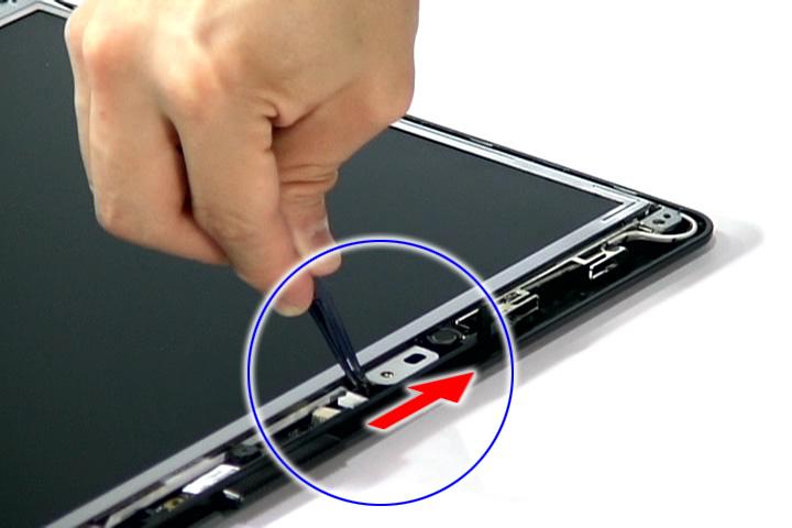
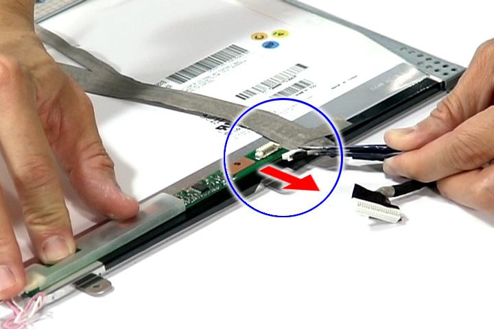
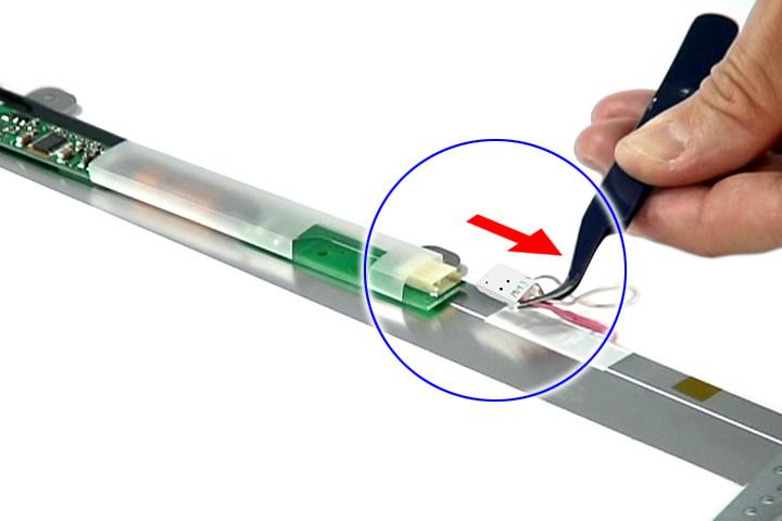
1. See “Removing the Battery Pack” on page 60. 2. See “Removing the Lower Cover” on page 62. 3. See “Removing the DIMM” on page 63. 4. See “Removing the WLAN Board Modules” on page 64. 5. See “Removing the Middle Cover and the Power Board” on page 74. 6. See “Removing the Keyboard” on page 76. 7. See “Removing the LCD Module” on page 78. 8. See “Removing the LCD Bezel” on page 94. 9. See “Removing the LCD module with the Brackets” on page 95. 10. Disconnect the inverter board cable from its connector, then disconnect the 2P cable on the inverter board to remove it.
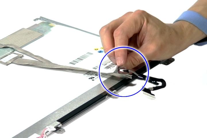
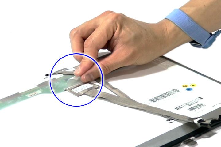
11. Detach the acetic tapes holding the FPC cable from the LCD panel and detach the acetic tape securing the FPC connector.
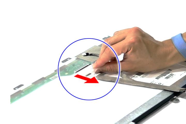
12. Disconnect the FPC cable from the LCD panel.
1. See “Removing the Battery Pack” on page 60. 2. See “Removing the Lower Cover” on page 62. 3. See “Removing the DIMM” on page 63. 4. See “Removing the WLAN Board Modules” on page 64. 5. See “Removing the Middle Cover and the Power Board” on page 74. 6. See “Removing the Keyboard” on page 76. 7. See “Removing the LCD Module” on page 78. 8. See “Removing the LCD Bezel” on page 94. 9. See “Removing the LCD module with the Brackets” on page 95. 10. See “Removing the Inverter Board and FPC Cable” on page 96. 11. Remove the eight screws (F) securing the left and right LCD brackets to remove the brackets.
Step Size (Quantity) Color Torque
1~8 M2 x L3 (8) Silver 1.6 kgf-cm
Removing the Left and Right Hinge
1. See “Removing the Battery Pack” on page 60. 2. See “Removing the Lower Cover” on page 62. 3. See “Removing the DIMM” on page 63. 4. See “Removing the WLAN Board Modules” on page 64. 5. See “Removing the Middle Cover and the Power Board” on page 74. 6. See “Removing the Keyboard” on page 76. 7. See “Removing the LCD Module” on page 78. 8. See “Removing the LCD Bezel” on page 94. 9. See “Removing the LCD module with the Brackets” on page 95.
Step Size (Quantity) Color Torque
1~2 M2.5 x L5 (2) Silver 2.5 kgf-cm
11. Remove the left and right hinge from the back cover.
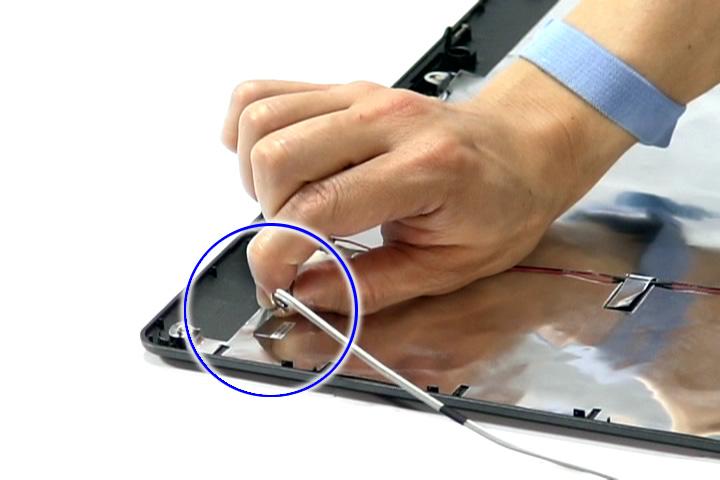
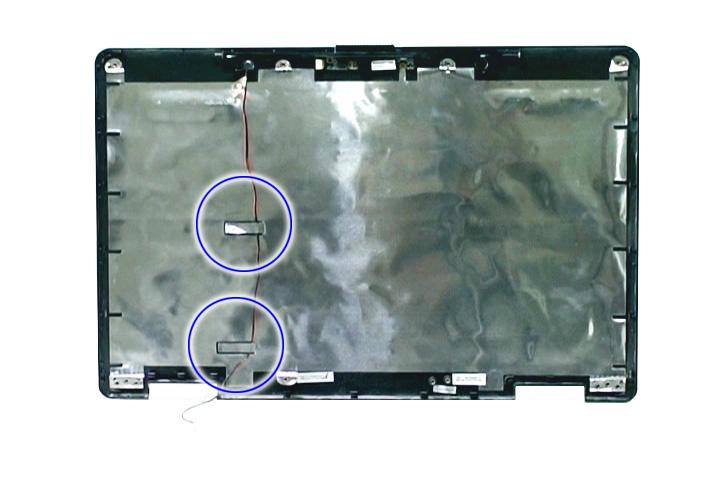
Removing the Antennas
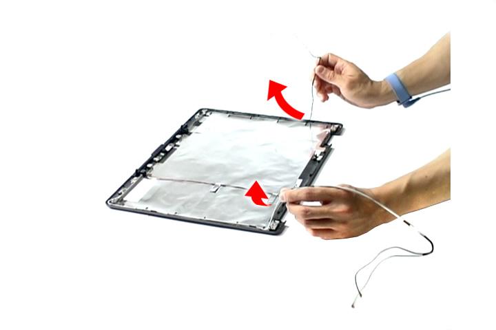
1. See “Removing the Battery Pack” on page 60. 2. See “Removing the Lower Cover” on page 62. 3. See “Removing the DIMM” on page 63. 4. See “Removing the WLAN Board Modules” on page 64. 5. See “Removing the Middle Cover and the Power Board” on page 74. 6. See “Removing the Keyboard” on page 76. 7. See “Removing the LCD Module” on page 78. 8. See “Removing the LCD Bezel” on page 94. 9. See “Removing the LCD module with the Brackets” on page 95. 10. See “Removing the Left and Right Hinge” on page 97. 11. Release the antenna cables from the latches.

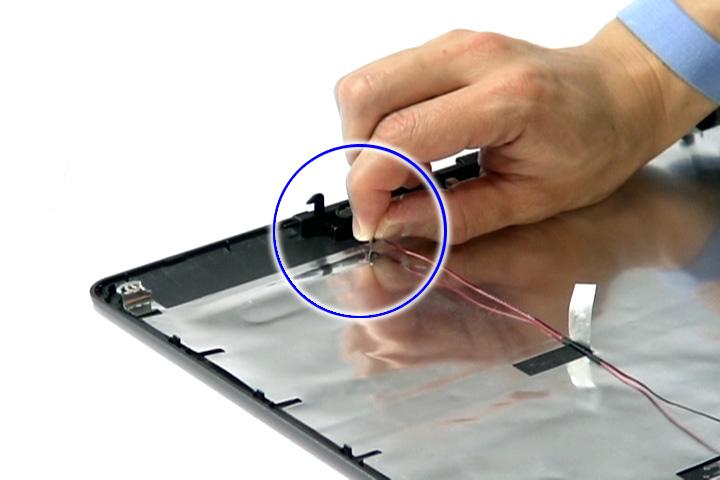
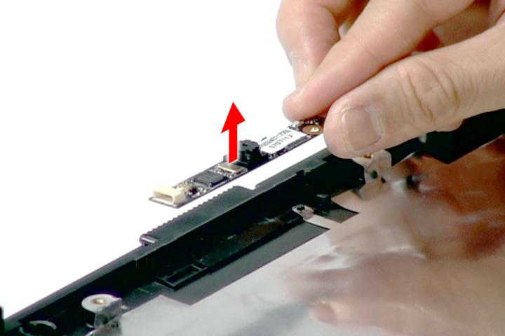
Removing the Internal Microphone and Web Camera
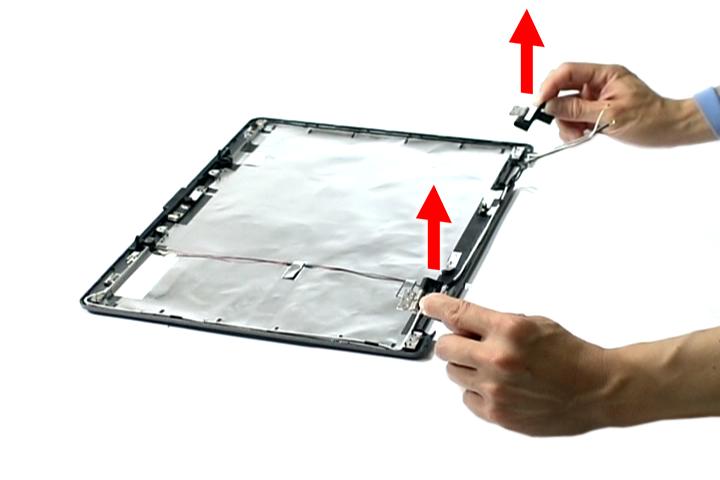
1. See “Removing the Battery Pack” on page 60. 2. See “Removing the Lower Cover” on page 62. 3. See “Removing the DIMM” on page 63. 4. See “Removing the WLAN Board Modules” on page 64. 5. See “Removing the Middle Cover and the Power Board” on page 74. 6. See “Removing the Keyboard” on page 76. 7. See “Removing the LCD Module” on page 78. 8. See “Removing the LCD Bezel” on page 94. 9. See “Removing the LCD module with the Brackets” on page 95. 10. See “Removing the Left and Right Hinge” on page 97. 11. See “Removing the Antennas” on page 98. 12. Release the internal microphone cable from the back cover.
13. Remove the tape holding the internal microphone in place.
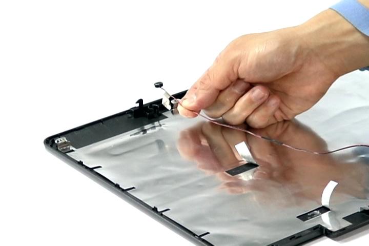
15. Remove the Web camera from the back cover.
Troubleshooting
Use the following procedure as a guide for computer problems. NOTE: The diagnostic tests are intended to test only Acer products. Non-Acer products, prototype cards, or modified options can give false errors and invalid system responses. 1. Obtain the failing symptoms in as much detail as possible. 2. Verify the symptoms by attempting to re-create the failure by running the diagnostic test or by repeating the same operation. 3. Use the following table with the verified symptom to determine which page to go to.
Symptoms (Verified)
Power failure. (The power indicator does not go on or stay on.) POST does not complete. No beep or error codes are indicated.
POST detects an error and displayed messages on screen. Other symptoms (i.e. LCD display problems or others). Symptoms cannot be re-created (intermittent problems).
Go To
“Power System Check” on page 103.
“Power-On Self-Test (POST) Error Message” on page 106 “Undetermined Problems” on page 120 “Error Message List” on page 107
“Power-On Self-Test (POST) Error Message” on page 106 Use the customer-reported symptoms and go to “Power-On Self-Test (POST) Error Message” on page 106 “Intermittent Problems” on page 119 “Undetermined Problems” on page 120
External Diskette Drive Check
Do the following to isolate the problem to a controller, driver, or diskette. A write-enabled, diagnostic diskette is required. NOTE: Make sure that the diskette does not have more than one label attached to it. Multiple labels can cause damage to the drive or cause the drive to fail. Do the following to select the test device. 1. Boot from the diagnostics diskette and start the diagnostics program. 2. See if FDD Test is passed as the program runs to FDD Test. 3. Follow the instructions in the message window. If an error occurs with the internal diskette drive, reconnect the diskette connector on the system board. If the error still remains: 1. Reconnect the external diskette drive/DVD-ROM module. 2. Replace the external diskette drive/CD-ROM module. 3. Replace the main board.
External CD-ROM Drive Check
Do the following to isolate the problem to a controller, drive, or CD-ROM. Make sure that the CD-ROM does not have any label attached to it. The label can cause damage to the drive or can cause the drive to fail. Do the following to select the test device: 1. Boot from the diagnostics diskette and start the diagnostics program. 2. See if CD-ROM Test is passed when the program runs to CD-ROM Test. 3. Follow the instructions in the message window. If an error occurs, reconnect the connector on the System board. If the error still remains: 1. Reconnect the external diskette drive/CD-ROM module. 2. Replace the external diskette drive/CD-ROM module. 3. Replace the main board.
Keyboard or Auxiliary Input Device Check
Remove the external keyboard if the internal keyboard is to be tested. If the internal keyboard does not work or an unexpected character appears, make sure that the flexible cable extending from the keyboard is correctly seated in the connector on the system board. If the keyboard cable connection is correct, run the Keyboard Test. If the tests detect a keyboard problem, do the following one at a time to correct the problem. Do not replace a non-defective FRU: 1. Reconnect the keyboard cables. 2. Replace the keyboard. 3. Replace the main board.
The following auxiliary input devices are supported by this computer: ❑ Numeric keypad
❑ External keyboard If any of these devices do not work, reconnect the cable connector and repeat the failing operation.
Memory check
Memory errors might stop system operations, show error messages on the screen, or hang the system. 1. Boot from the diagnostics diskette and start the doagmpstotics program (please refer to main board. 2. Go to the diagnostic memory in the test items. 3. Press F2 in the test items. 4. Follow the instructions in the message window. NOTE: Make sure that the DIMM is fully installed into the connector. A loose connection can cause an error.
Power System Check
To verify the symptom of the problem, power on the computer using each of the following power sources: 1. Remove the battery pack. 2. Connect the power adapter and check that power is supplied. 3. Disconnect the power adapter and install the charged battery pack; then check that power is supplied by the battery pack. If you suspect a power problem, see the appropriate power supply check in the following list: ❑ “Check the Power Adapter” on page 104 ❑ “Check the Battery Pack” on page 105
Unplug the power adapter cable from the computer and measure the output voltage at the plug of the power adapter cable. See the following figure
Pin 1: +19 to +20.5V Pin 2: 0V, Ground
1. If the voltage is not correct, replace the power adapter. 2. If the voltage is within the range, do the following: ❑ Replace the System board. ❑ If the problem is not corrected, see “Undetermined Problems” on page 120. ❑ If the voltage is not correct, go to the next step. NOTE: An audible noise from the power adapter does not always indicate a defect. 3. If the power-on indicator does not light up, check the power cord of the power adapter for correct continuity and installation. 4. If the operational charge does not work, see “Check the Battery Pack” on page 105.
To check the battery pack, do the following: From Software: 1. Check out the Power Management in control Panel 2. In Power Meter, confirm that if the parameters shown in the screen for Current Power Source and Total
Battery Power Remaining are correct. 3. Repeat the steps 1 and 2, for both battery and adapter. 4. This helps you identify first the problem is on recharging or discharging. From Hardware: 1. Power off the computer. 2. Remove the battery pack and measure the voltage between battery terminals 1(+) and 6(ground). 3. If the voltage is still less than 7.5 Vdc after recharging, replace the battery. To check the battery charge operation, use a discharged battery pack or a battery pack that has less than 50% of the total power remaining when installed in the computer. If the battery status indicator does not light up, remove the battery pack and let it return to room temperature. Re-install the battery pack. If the charge indicator still does not light up, replace the battery pack. If the charge indicator still does not light up, replace the DC/DC charger board.
Touchpad Check
If the touchpad doesn’t work, do the following actions one at a time to correct the problem. Do not replace a non-defective FRU: 1. Reconnect the touchpad cables. 2. Replace the touchpad. 3. Replace the system board. After you use the touchpad, the pointer drifts on the screen for a short time. This self-acting pointer movement can occur when a slight, steady pressure is applied to the touchpad pointer. This symptom is not a hardware problem. No service actions are necessary if the pointer movement stops in a short period of time.
The POST error message index lists the error message and their possible causes. The most likely cause is listed first. NOTE: Perform the FRU replacement or actions in the sequence shown in FRU/Action column, if the FRU replacement does not solve the problem, put the original part back in the computer. Do not replace a non-defective FRU.
This index can also help you determine the next possible FRU to be replaced when servicing a computer. If the symptom is not listed, see “Undetermined Problems” on page 120. The following lists the error messages that the BIOS displays on the screen and the error symptoms classified by function. NOTE: Most of the error messages occur during POST. Some of them display information about a hardware device, e.g., the amount of memory installed. Others may indicate a problem with a device, such as the way it has been configured. NOTE: If the system fails after you make changes in the BIOS Setup Utility menus, reset the computer, enter Setup and install Setup defaults or correct the error.
Error Code List
Error Codes Error Messages
006 Equipment Configuration Error Causes: 1. CPU BIOS Update Code Mismatch 2. IDE Primary Channel Master Drive Error (THe causes will be shown before “Equipment Configuration Error”) 010 Memory Error at xxxx:xxxx:xxxxh (R:xxxxh, W:xxxxh) 070 Real Time Clock Error 071 CMOS Battery Bad 072 CMOS Checksum Error 110 System disabled. Incorrect password is specified. <No error code> Battery critical LOW In this situation BIOS will issue 4 short beeps then shut down system, no message will show. <No error code> Thermal critical High In this situation BIOS will shut down system, not show message.
Error Message List
Error Messages
FRU/Action in Sequence
Failure Fixed Disk Reconnect hard disk drive connector. “Load Default Settings” in BIOS Setup Utility. Hard disk drive System board Stuck Key see “Keyboard or Auxiliary Input Device Check” on page 102. Keyboard error see “Keyboard or Auxiliary Input Device Check” on page 102. Keyboard Controller Failed see “Keyboard or Auxiliary Input Device Check” on page 102. Keyboard locked - Unlock key switch Unlock external keyboard Monitor type does not match CMOS - Run Setup Run “Load Default Settings” in BIOS Setup Utility. Shadow RAM Failed at offset: nnnn BIOS ROM System board System RAM Failed at offset: nnnn DIMM System board Extended RAM Failed at offset: nnnn DIMM System board
System battery is dead - Replace and run Setup System CMOS checksum bad - Default configuration used Replace RTC battery and Run BIOS Setup Utility to reconfigure system time, then reboot system. RTC battery Run BIOS Setup Utility to reconfigure system time, then reboot system.
Error Messages FRU/Action in Sequence
System timer error RTC battery Run BIOS Setup Utility to reconfigure system time, then reboot system. System board Real time clock error RTC battery Run BIOS Setup Utility to reconfigure system time, then reboot system. System board
Previous boot incomplete - Default configuration used Run “Load Default Settings” in BIOS Setup Utility. RTC battery System board
Memory size found by POST differed from CMOS
Run “Load Default Settings” in BIOS Setup Utility. DIMM System board Diskette drive A error Check the drive is defined with the proper diskette type in BIOS Setup Utility See “External Diskette Drive Check” on page 102. Incorrect Drive A type - run SETUP Check the drive is defined with the proper diskette type in BIOS Setup Utility System cache error - Cache disabled System board CPU ID: System board DMA Test Failed DIMM System board Software NMI Failed DIMM System board Fail-Safe Timer NMI Failed DIMM System board Device Address Conflict Run “Load Default Settings” in BIOS Setup Utility. RTC battery System board Allocation Error for device Run “Load Default Settings” in BIOS Setup Utility. RTC battery System board Failing Bits: nnnn DIMM BIOS ROM System board Fixed Disk n None Invalid System Configuration Data BIOS ROM System board I/O device IRQ conflict Run “Load Default Settings” in BIOS Setup Utility. RTC battery System board Operating system not found Enter Setup and see if fixed disk and drive A: are properly identified. Diskette drive Hard disk drive System board
Error Message List
No beep Error Messages
No beep, power-on indicator turns off and LCD is blank.
No beep, power-on indicator turns on and LCD is blank.
No beep, power-on indicator turns on and LCD is blank. But you can see POST on an external CRT.
No beep, power-on indicator turns on and a blinking cursor shown on LCD during POST. No beep during POST but system runs correctly.
FRU/Action in Sequence
Power source (battery pack and power adapter). See “Power System Check” on page 103.. Ensure every connector is connected tightly and correctly. Reconnect the DIMM. LED board. System board. Power source (battery pack and power adapter). See “Power System Check” on page 103.. Reconnect the LCD connector Hard disk drive LCD inverter ID LCD cable LCD Inverter LCD System board Reconnect the LCD connectors. LCD inverter ID LCD cable LCD inverter LCD System board Ensure every connector is connected tightly and correctly. System board
Speaker System board
Code Beeps POST Routine Description
02h Verify Real Mode 03h Disable Non-Maskable Interrupt (NMI) 04h Get CPU type 06h Initialize system hardware 08h Initialize chipset with initial POST values 09h Set IN POST flag 0Ah Initialize CPU registers 0Bh Enable CPU cache 0Ch Initialize caches to initial POST values 0Eh Initialize I/O component 0Fh Initialize the local bus IDE 10h Initialize Power Management 11h Load alternate registers with initial POST values 12h Restore CPU control word during warm boot 13h Initialize PCI Bus Mastering devices 14h Initialize keyboard controller 16h 1-2-2-3 BIOS ROM checksum 17h Initialize cache before memory autosize 18h 8254 timer initialization 1Ah 8237 DMA controller initialization 1Ch Reset Programmable Interrupt Controller 20h 1-3-1-1 Test DRAM refresh 22h 1-3-1-3 Test 8742 Keyboard Controller 24h Set ES segment register to 4 GB 26h Enable A20 line 28h Autosize DRAM 29h Initialize POST Memory Manager 2Ah Clear 215 KB base RAM 2Ch 1-3-4-1 RAM failure on address line xxxx 2Eh 1-3-4-3 RAM failure on data bits xxxx of low byte of memory bus 2Fh Enable cache before system BIOS shadow 30h 1-4-1-1 RAM failure on data bits xxxx of high byte of memory bus 32h Test CPU bus-clock frequency 33h Initialize Phoenix Dispatch Manager 36h Warm start shut down 38h Shadow system BIOS ROM 3Ah Autosize cache
Code Beeps
POST Routine Description
3Ch Advanced configuration of chipset registers 3Dh Load alternate registers with CMOS values 42h Initialize interrupt vectors 45h POST device initialization 46h 2-1-2-3 Check ROM copyright notice 48h Check video configuration against CMOS 49h Initialize PCI bus and devices 4Ah Initialize all video adapters in system 4Bh QuietBoot start (optional) 4Ch Shadow video BIOS ROM 4Eh Display BIOS copyright notice 50h Display CPU type and speed 51h Initialize EISA board 52h Test keyboard 54h Set key click if enabled 58h 2-2-3-1 Test for unexpected interrupts 59h Initialize POST display service 5Ah Display prompt “Press F2 to enter SETUP” 5Bh Disable CPU cache 5Ch Test RAM between 512 and 640 KB 60h Test extended memory 62h Test extended memory address lines 64h Jump to User Patch1 66h Configure advanced cache registers 67h Initialize Multi Processor APIC 68h Enable external and CPU caches 69h Setup System Management Mode (SMM) area 6Ah Display external L2 cache size 6Bh Load custom defaults (optional) 6Ch Display shadow-area message 6Eh Display possible high address for UMB recovery 70h Display error messages 72h Check for configuration errors 76h Check for keyboard errors 7Ch Set up hardware interrupt vectors 7Eh Initialize coprocessor if present 80h Disable onboard Super I/O ports and IRQs 81h Late POST device initialization
Code Beeps
POST Routine Description
82h Detect and install external RS232 ports 83h Configure non-MCD IDE controllers 84h Detect and install external parallel ports 85h Initialize PC-compatible PnP ISA devices 86h Re-initialize onboard I/O ports 87h Configure Motherboard Configurable Devices (optional) 88h Initialize BIOS Area 89h Enable Non-Maskable Interrupts (NMIs) 8Ah Initialize Extended BIOS Data Area 8Bh Test and initialize PS/2 mouse 8Ch Initialize floppy controller 8Fh Determine number of ATA drives (optional) 90h Initialize hard-disk controllers 91h Initialize local-bus hard-disk controllers 92h Jump to UserPatch2 93h Build MPTABLE for multi-processor boards 95h Install CD ROM for boot 96h Clear huge ES segment register 97h Fixup Multi Processor table 98h 1-2 Search for option ROMs. One long, two short beeps on checksum failure. 99h Check for SMART drive (optional) 9Ah Shadow option ROMs 9Ch Set up Power Management 9Dh Initialize security engine (optional) 9Eh Enable hardware interrupts 9Fh Determine number of ATA and SCSI drives A0h Set time of day A2h Check key lock A4h Initialize Typematic rate A8h Erase F2 prompt AAh Scan for F2 key stroke ACh Enter SETUP AEh Clear Boot flag B0h Check for errors B2h POST done- prepare to boot operating system B4h 1 One short beep before boot B5h Terminate QuietBoot (optional) B6h Check password (optional)
Code Beeps
POST Routine Description
B9h Prepare Boot BAh Initialize DMI parameters BBh Initialize PnP Option ROMs BCh Clear parity checkers BDh Display MultiBoot menu BEh Clear screen (optional) BFh Check virus and backup reminders C0h Try to boot with INT 19 C1h Initialize POST Error Manager (PEM) C2h Initialize error logging C3h Initialize error display function C4h Initialize system error handler C5h PnPnd dual CMOS (optional) C6h Initialize notebook docking (optional) C7h Initialize notebook docking late C8h Force check (optional) C9h Extended checksum (optional) D2h Unknown interrupt
Code Beeps
E0h Initialize the chipset E1h Initialize the bridge E2h Initialize the CPU E3h Initialize the system timer E4h Initialize system I/O E5h Check force recovery boot E6h Checksum BIOS ROM E7h Go to BIOS E8h Set Huge Segment E9h Initialize Multi Processor EAh Initialize OEM special code EBh Initialize PIC and DMA ECh Initialize Memory type EDh Initialize Memory size EEh Shadow Boot Block EFh System memory test F0h Initialize interrupt vectors F1h Initialize Run Time Clock F2h Initialize video F3h Initialize System Management Mode F4h 1 Output one beep before boot
Code
Beeps
F5h Boot to Mini DOS F6h Clear Huge Segment F7h Boot to Full DOS
LCD-Related Symptoms
Symptom / Error
LCD backlight doesn't work LCD is too dark LCD brightness cannot be adjusted LCD contrast cannot be adjusted
Unreadable LCD screen Missing pels in characters Abnormal screen Wrong color displayed
LCD has extra horizontal or vertical lines displayed.
Action in Sequence
Enter BIOS Utility to execute “Load Setup Default Settings”, then reboot system. Reconnect the LCD connectors. Keyboard (if contrast and brightness function key doesn't work). LCD inverter ID LCD cable LCD inverter LCD System board Reconnect the LCD connector LCD inverter ID LCD cable LCD inverter LCD System board LCD inverter ID LCD inverter LCD cable LCD System board
Indicator-Related Symptoms
Symptom / Error
Indicator incorrectly remains off or on, but system runs correctly Reconnect the inverter board Inverter board System board
Action in Sequence
Power-Related Symptoms
Symptom / Error Action in Sequence
Power shuts down during operation Power source (battery pack and power adapter). See “Power System Check” on page 103. Battery pack Power adapter Hard drive & battery connection board System board The system doesn’t power-on. Power source (battery pack and power adapter). See “Power System Check” on page 103. Battery pack Power adapter Hard drive & battery connection board System board
Symptom / Error
Action in Sequence
The system doesn’t power-off. Power source (battery pack and power adapter). See “Power System Check” on page 103. Hold and press the power switch for more than 4 seconds. System board Battery can’t be charged See “Check the Battery Pack” on page 105. Battery pack System board
PCMCIA-Related Symptoms
Symptom / Error Action in Sequence
System cannot detect the PC Card (PCMCIA)
PCMCIA slot assembly System board PCMCIA slot pin is damaged. PCMCIA slot assembly
Memory-Related Symptoms
Symptom / Error
Memory count (size) appears different from actual size. Enter BIOS Setup Utility to execute “Load Default Settings, then reboot system. DIMM System board
Action in Sequence
Speaker-Related Symptoms
Symptom / Error
In Windows, multimedia programs, no sound comes from the computer.
Internal speakers make noise or emit no sound. Audio driver Speaker System board Speaker System board
Action in Sequence
Power Management-Related Symptoms
Symptom / Error Action in Sequence
The system will not enter hibernation See “Save to Disk (S4)” on page 38. Keyboard (if control is from the keyboard) Hard disk drive System board
The system doesn't enter hibernation mode and four short beeps every minute.
The system doesn’t enter standby mode after closing the LCD Press Fn+oand see if the computer enters hibernation mode. Touchpad Keyboard Hard disk connection board Hard disk drive System board See “Save to Disk (S4)” on page 38. LCD cover switch System board
Symptom / Error
The system doesn't resume from hibernation mode.
Action in Sequence
See “Save to Disk (S4)” on page 38. Hard disk connection board Hard disk drive System board
The system doesn't resume from standby mode after opening the LCD. See “Save to Disk (S4)” on page 38. LCD cover switch System board
Battery fuel gauge in Windows doesn’t go higher than 90%.
Remove battery pack and let it cool for 2 hours. Refresh battery (continue use battery until power off, then charge battery). Battery pack System board System hangs intermittently. Reconnect hard disk/CD-ROM drives. Hard disk connection board System board
Peripheral-Related Symptoms
Symptom / Error Action in Sequence
System configuration does not match the installed devices.
Enter BIOS Setup Utility to execute “Load Default Settings”, then reboot system. Reconnect hard disk/CD-ROM/diskette drives. External display does not work correctly. Press Fn+F5, LCD/CRT/Both display switching System board USB does not work correctly System board Print problems. Ensure the “Parallel Port” in the “Onboard Devices Configuration” of BIOS Setup Utility is set to Enabled. Onboard Devices Configuration Run printer self-test. Printer driver Printer cable Printer System Board Serial or parallel port device problems. Ensure the “Serial Port” in the Devices Configuration” of BIOS Setup Utility is set to Enabled. Device driver Device cable Device System board
Keyboard/Touchpad-Related Symptoms
Symptom / Error
Keyboard (one or more keys) does not work. Reconnect the keyboard cable. Keyboard System board
Action in Sequence
Symptom / Error
Action in Sequence
Touchpad does not work. Reconnect touchpad cable. Touchpad board System board
Modem-Related Symptoms
Symptom / Error Action in Sequence
Internal modem does not work correctly. Modem phone port modem combo board System board NOTE: If you cannot find a symptom or an error in this list and the problem remains, see “Undetermined Problems” on page 120.
Intermittent system hang problems can be caused by a variety of reasons that have nothing to do with a hardware defect, such as: cosmic radiation, electrostatic discharge, or software errors. FRU replacement should be considered only when a recurring problem exists. When analyzing an intermittent problem, do the following: 1. Run the advanced diagnostic test for the system board in loop mode at least 10 times. 2. If no error is detected, do not replace any FRU. 3. If any error is detected, replace the FRU. Rerun the test to verify that there are no more errors.
The diagnostic problems does not identify which adapter or device failed, which installed devices are incorrect, whether a short circuit is suspected, or whether the system is inoperative. Follow these procedures to isolate the failing FRU (do not isolate non-defective FRU). NOTE: Verify that all attached devices are supported by the computer. NOTE: Verify that the power supply being used at the time of the failure is operating correctly. (See “Power System Check” on page 103.): 1. Power-off the computer. 2. Visually check them for damage. If any problems are found, replace the FRU. 3. Remove or disconnect all of the following devices: ❑ Non-Acer devices ❑ Printer, mouse, and other external devices ❑ Battery pack ❑ Hard disk drive ❑ DIMM ❑ CD-ROM/Diskette drive Module ❑ PC Cards 4. Power-on the computer. 5. Determine if the problem has changed. 6. If the problem does not recur, reconnect the removed devices one at a time until you find the failing FRU. 7. If the problem remains, replace the following FRU one at a time. Do not replace a non-defective FRU: ❑ System board ❑ LCD assembly
Jumper and Connector Locations
Top View
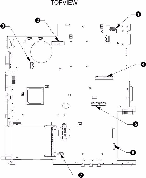
No. Description No. Description
1 Power Cable Connector 5 Fingerprint/Touchpad Connector 2 LCD Cable Connector 6 Bluetooth Connector 3 Touchpad Board Connector 7 Speaker Connector 4 Keyboard Connector
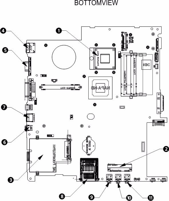
No. Description No.
Description
1 CPU 7 USB Connector 2 SATA Connector 8 Card Reader 3 PC Card Reader 9 Line-out jack 4 LAN Connector 10 Mic-in jack 5 CRT Connector 11 Headphone jack 6 1394 Connector
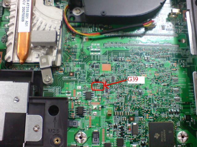
For RD and CSD to debug easily, the system provide one hardware DIP switch for Bypassing Password Check, and one Hotkey to enable BIOS Recovery. 1. DIP Switches:
2. Hotkey to enable BIOS Recovery: Fn+ESC, then Power Button. To use this function, it is strongly recommended that the AC adapter is connected to the system and plug-in to a wall outlet and the Battery is also in the system Bypassing Password Check (SW1): If the user has set Password (power-on or setup password) for security reason, BIOS will check password during POST or when entering the BIOS setup menu. However, if it is necessary to ignore the password check, the user may enable DIP SW1 to bypass password check. BIOS Recovery: Boot Block is a special block of BIOS. It is used to boot up the system with minimum BIOS initialization. The user can enable this feature to restore the BIOS to a successful one if previous BIOS flashing process fails. 1. DIP Location: RD/CSD can enable or disable this function by switching the DIP. The DIP switch is located as shown in the figure below:
2. Clear Password DIP SW1: Bypassing Password Check, Disabled by default. Switching it to ON then powering on the system will force the BIOS to clear Supervisor and User passwords. The power-on, setup password, and the HDD password are all cleared. 3. Restore BIOS by the Crisis Disk Enable this function by pressing the combination: Fn+ESC, and pressing the Power Button. To use this function, it is strongly recommended that the AC adapter is connected to the system and plug-in to a wall outlet and the Battery is also in the system. If this function is enabled, the system will force the BIOS to enter a
DIP Default Setting Description
SW1 Disabled (High) Bypassing Password Check
special BIOS block, called BootBlock. RD/CSD can use this special BIOS code to recover the BIOS to a successful one if previous BIOS flashing process fails. However, before doing this, one Crisis Disk should be prepared in WinXP. Detailed steps are as the followings: a. Prepare the Crisis Disk in WinXP. b. Insert the Crisis Disk to a USB floppy drive which is attached to the failed machine. c. While the system is turned off, press and hold Fn+ESC, then press Power Button. The system should be powered on with Crisis Recovery process. d. BootBlock BIOS starts to restore the failed BIOS code. Short beeps should be heard when flashing. e. If the flashing process is finished, a long beep should be heard. f. Power down the system after you hear the long beep. If the crisis recovery process is finished, the system should be powered on with the successful BIOS. RD/CSD can then update the BIOS to a workable one by regular BIOS flashing process.