1 minute read
MAINTENANCE


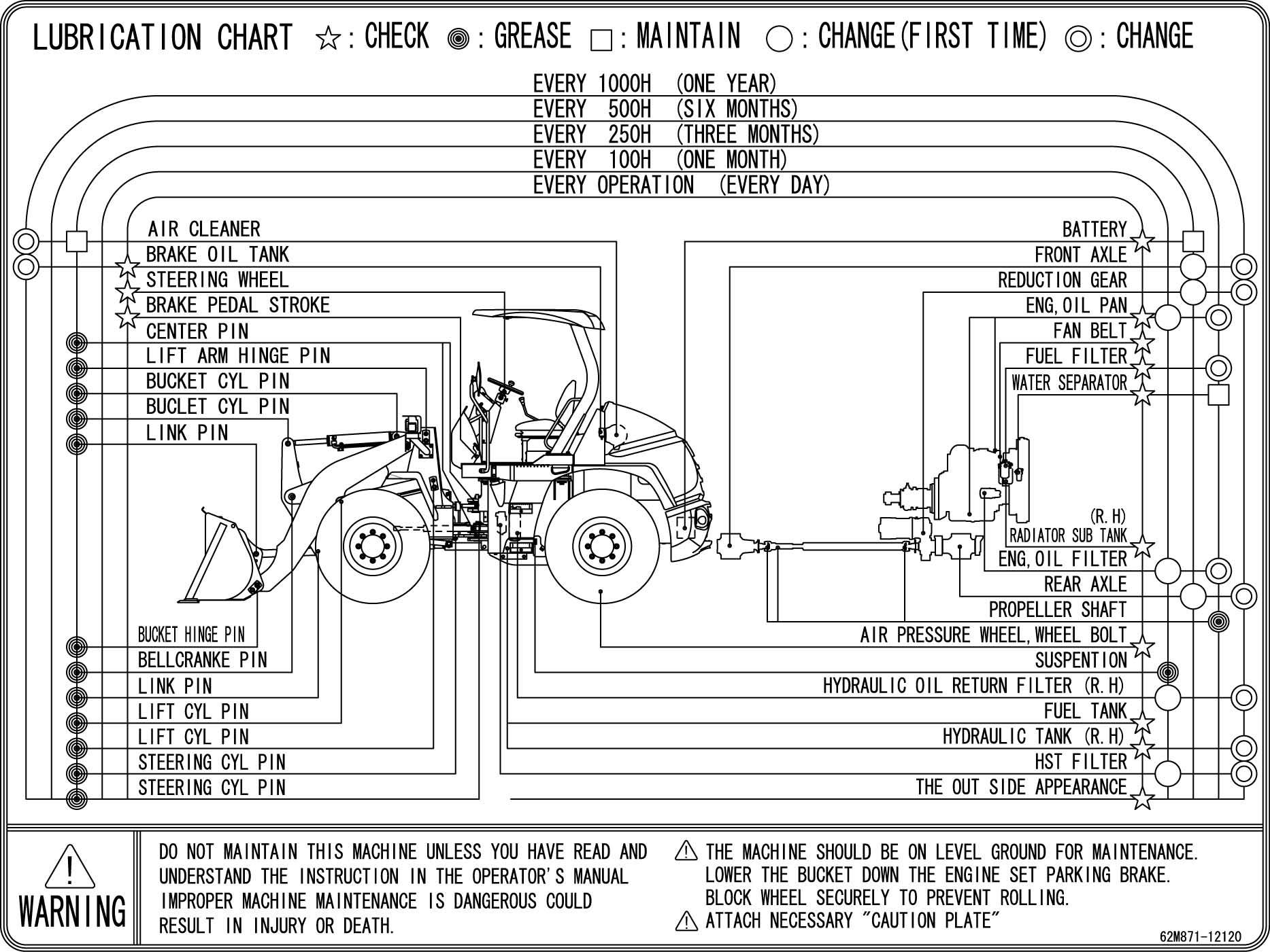
The maintenance guide table is affixed on the under of the operator’s seat. Lubricate and/or service the parts at the intervals as instructed in the table so that all necessary maintenance can be performed regularly.
Maintenance
Preparations for Inspection and Maintenance
d WARNING: The lift arm may move up while holding ride control switch (1) in the ON position. Be sure to turn the ride control switch OFF in order to avoid accidents due to unexpected movement of the lift arm.
d CAUTION: If the machine is unexpectedly moved, serious accident may result. Be sure to apply the parking brake when parking the machine.
Unless especially specified, park the machine by following the procedures below before beginning the inspection and/or maintenance work.
1. Park the machine on solid level surface.
2. Lower the working tools such as the bucket to the ground.
3. Turn ride control switch (1) (optional) OFF.
4. Place F-N-R lever (3) in neutral (N) and place neutral lever lock (4) to LOCK position (3).
5. Apply the parking brake by turning parking brake switch (5) ON.
6. Wedge the tires.
7. Run the engine for 5 minutes to cool the engine. Turn the key switch OFF and stop the engine. Remove the key from the switch. Fully move the loader control lever 3 to 4 strokes to release residual pressure in the hydraulic system. In case inspection and/or maintenance must be performed with the engine kept running, use a safety lookout.
8. Be sure to place loader control lever lock (2) in the LOCK position.
9. Begin to work only after attaching a “Do Not Operate” tag in a highly visible place such as on the cab door or the loader control lever.
Maintenance
Lock Frames
d WARNING: Before beginning to work near the axle of frames (3), (4), install articulation lock bar (1) to securely lock and prohibit movement between the front and rear frames (3) and (4). Avoid accidents due to unexpected movement of the machine.
1. Align the front and rear frames (3) and (4) centers with each other.
2. Remove lock pin (2) and remove articulation lock bar (1) from the front side pin hole on front frame (3).
3. Install one end of articulation lock bar (1) to the mounting pin of rear frame (4). Secure articulation lock bar (1) in position with lock pin (2).