
25 minute read
Procedures for Operation/Assembly and Disassembly of Hydraulic Cylinder


1.Explanation of functions (1) Cylinder head assembly Prevent external oil leaks inside the cylinder and entry of dusts from the outside. [1] Dust seal (01) Prevent entry of dusts from the outside. Also scrape off any mud or other impurities sticking to the rod. [2] Snap ring (02) Retain the dust seal. [3] Buffer ring + rod packing (03 + 04) Prevent cylinder oil leakage from the rod section to the outside. [4] Bushing (05) Prevent metal contact of the rod and cylinder head. [5] Snap ring (06) Retain the bushing (05). [6] Collar (07) Narrow the flow path of the oil by plunging the plunger near the extension stroke end and establish the containment pressure. (To alleviate the shock on the extension stroke end)
(2) Piston assembly
Cut off the oil on the extension side and retraction side and move the rod. [1] Piston ring (08) Cut off the oil on the extension side and retraction side. [2] Wear ring (09) Prevent metal contact of the cylinder tube and piston. [3] Ring (10) Prevent damage to the piston ring due to diesel ignition or foreign matter. [4] Screw (11) Retain the piston. [5] Plunger (12) Narrow the flow path of the oil by plunging to the collar near the extension stroke end and establish the containment pressure. (To alleviate the shock on the extension stroke end) [6] Plunger (13) Narrow the flow path of the oil by plunging to the bottom near the retraction stroke end and establish the containment pressure. (To alleviate the shock on the retraction stroke end) [7] Ball (14) Retain the plunger (12). Also support plunger eccentricity. [8] Cap (15) Retain the ball (14).

2.Handling precautions (1) Precautions for installing the cylinder on the machine •When installing the cylinder on the machine or removing it from the machine, check safety and suspend the cylinder. Suspending the cylinder on the line section is not only dangerous but it can damage the cylinder. Use a band to secure the rod in the fully retracted state. Not securing the piston rod is dangerous because the piston rod might fly out unexpectedly. Or the rod can become scratched, preventing use of the rod. •Welding work after cylinder installation can result in major damage. Electric welding on the cylinder or even at a position separated from the cylinder can generate a spark within the cylinder and require replacing with a new cylinder. •Mask the cylinder when painting the machine. If the cylinder is operated with paint sticking to the rod surface and the dust seal, the dust seal does not function adequately, greatly interfering with cylinder functions. For example, dirt and paint from the outside can easily get into the cylinder, damaging the seal parts and extremely reducing the cylinder service life. •Clean the cylinder before installing it. (2) Usage cautions •Use under the determined conditions. Use of hydraulic oil other than that specified can cause rapid deterioration of and damage to seal parts. Setting the relief valve to a value higher than that on the assembly diagram can create a danger of damage to the cylinder. General sealing materials become damaged immediately at high ambient temperature (about 100 ℃ or higher) or low ambient temperature (-20 ℃ or lower). Special seals are required, so check whether the cylinder being used complies with this requirement. The number one cause of cylinder trouble is oil leaks due to rod scratches. Operate carefully to avoid scratching. •Warm up the equipment adequately before work. After the cylinder has been stopped for a long time, the seal parts inside the cylinder are stuck to the metal of sliding surfaces, so do not suddenly operate at the maximum pressure or speed. A new cylinder or one that has been left unused for a long time has much air built up inside, so the cylinder does not operate smoothly. Also, if the cylinder is suddenly pressurized without bleeding out the air, the adiabatic compression of the air generates high temperatures, which can burn and carbonize seal parts, leading to a drastically reduced functionality. Operate while paying attention to "always eliminate any air in the cylinder" by moving the cylinder slowly through a few full strokes under no load before starting work. •Safely secure the machine when stopping it temporarily or storing it. When the cylinder is installed, it cannot hold a fixed position for a long time. The cylinder oil can leak and a change in the hydraulic oil temperature can change the volume of the hydraulic oil in the cylinder. As a result, the cylinder extends and retracts, creating a danger of unexpected movement of the machine. Always stop the machine temporarily or store it in a safely secured position.
(3) Maintenance and inspection cautions •Always carry out daily maintenance inspections.
The most important point for realizing the cylinder functions for a longer time is "daily maintenance inspections". In order to ensure adequate functioning at all times, perform "3. Maintenance inspection and service". Constantly clean off any mud, water, dust, oil or grease stuck to the rod and keep the rod clean. However, do not use water to clean the dust seal and other seal sections. Wipe with a rag. When leaving the machine unused for a week or longer, apply antirust oil to the surface of the rod to prevent rusting. •Use Sumitomo specified parts for replacement parts.
Using parts not specified by Sumitomo can prevent the machine from operating with full functionality. Always use Sumitomo specified parts. •Be careful when assembling and disassembling parts too.
In particular, disassembling a cylinder head still installed on the machine can create a danger of unexpected movement of the machine. Always remove the cylinder from the machine before disassembling it. Assembling with dirty hands can get dirt inside the cylinder and not only reduce the cylinder service life but also damage other hydraulic equipment. Assemble under clean conditions. Use the thread part tightening torque indicated in the diagram. If the torque is either too low or too high, this can cause thread damage. •Strictly observe the cylinder storage standards.
3.Maintenance inspection and service
In order to ensure the hydraulic cylinder functions properly for a long time, periodically carry out maintenance inspection and service based on the "Autonomous inspection table". Repair any trouble locations quickly based on the trouble diagnostics. •For periodic inspection and service, first work to prevent any hazard to operators. Strive to prevent hazards by working with an attitude based on good sense.
Inspection and service location Inspection and service detail Daily Monthly Yearly Remarks
Appearance Is the cylinder clean (especially rod sliding sections)? Is any oil leaking from line installation sections or other fixed sections? Is there missing or peeling paint, or rust? ○
Operation Is operation smooth and free of abnormal noise and any other abnormality? ○
Is the responsiveness good?
○ Is any oil leaking from sliding sections? ○ Are there internal leaks? Is the operating pressure normal? Is the overload relief valve set pressure normal?
Hydraulic oil Is hydraulic oil dirty or deteriorated? Is hydraulic oil replaced periodically? Are filters inspected periodically?
Section for installation with main unit Is the supply of grease to pins adequate? Do pin sections have any abnormal noises or seizing? ○
Do pin sections have any backlash or wear? ○ Are pin seals normal? Are any installation screws loose or fallen out? ○ Retighten installation screws.
Piston rod section
Cylinder tube section (including line sections) Are there any loose bolts or nuts (threaded parts)?
Are sliding sections worn? Are sliding sections scratched or dented? ○ Is sliding section plating peeling off? ○ Are sliding sections bent? Are there any welding section cracks or damage? ○
Retighten threaded installation parts (bolts and nuts (threaded parts)). Are there any welding section cracks or damage? Are there large dents on the tube? When leaving rod sliding sections exposed for long periods, apply antirust oil to the rod.
4.Trouble diagnostics
Hydraulic cylinder trouble, countermeasure and solution It is not easy to discover trouble locations. The table below shows general symptoms, suggested causes and also solutions. For repairs, see the suggested causes and solutions in the table. The cause of machine problems are often not rooted in just a single part. Problems are often due to the relationship of one part with another. In some cases, solutions are required other than those given in the table.
Item Symptom 1 Piston rod sliding section oil leak Inspection after assembly.) (For the judgment values, see 6. (4) 2 Cylinder head matching section oil leak 3 Pipe and cylinder tube welding section oil leak 4 Operation defect
Item Symptom Related part Symptom
Piston rod A sliding surface has rust and scratches that catch on a fingernail.
1 Piston rod sliding section oil leak Plating is peeling off.
There is foreign matter caught in the inner or outer diameter section. There are scratches on the inner or outer diameter section. Countermeasure and solution
1. Remove the scratches with a whetstone to make the sliding surface smooth (1.5 s or lower). If oil continues to leak even if the rod surface is made smooth, the scratches may have damaged the rod packing or other seals, so disassemble and inspect. 2. If the scratches or rust cover too large an area to be repaired with a whetstone, replace the piston rod, rod packing, dust seal, or other seals and the piston rod bearing part. 1. Replate or replace the piston rod. 2. At this time, inspect the seals and piston rod bearing part as well and replace any that are damaged.
1. Remove the foreign matter. 2. If the packing is damaged, replace it.
1. Replace the part.
Rod packing Buffer ring The lips and groove section are locally carbonized (scorched). 1. This may be scorching due to adiabatic compression of air remaining in the cylinder. 2. When operating the cylinder for the first time after replacing a packing, run at low pressure and low speed to adequately bleed off the air.
The packing has lost its rubber elasticity and is in tatters. Also, the lip section is defective all the way around. 1. Replace the part. 2. This may be the end of the packing service life, deterioration of the hydraulic oil, or high temperature of the hydraulic oil. 1)Replace hydraulic oil with new oil. 2)Check the hydraulic oil temperature. (The oil temperature should be no higher than 80 ℃ .) 3)Check for local high temperature.
Item Symptom Related part Symptom Countermeasure and solution
Rod packing Buffer ring
Dust seal
1 Piston rod sliding section oil leak
Bearing part (bushing) There is major extrusion of the packing heel section.
1. Replace the part. 2. Abnormally high pressure may be operating on the packing. 1)Check the hydraulic oil pressure. 2)The part with attached buffer ring may have trouble with the buffer ring section. Inspect the buffer ring section. There is foreign matter caught in the lip. 1. Remove the foreign matter. The lip is damaged. There is other abnormal damage. 1. Replace the part.
There is major wear of the bushing and the gap with the piston rod exceeds *the maximum permissible value. (See 6. (3) Maintenance standards.) 1. Replace the part.
There are large scratches on a sliding surface. 1. Replace the part. 2. Inspect the piston rod at this time.
2
3 Cylinder head matching section oil leak
Pipe and cylinder tube welding section oil leak Cylinder head
O-ring A seal mounting section has scratches and rust.
Foreign matter is caught in the inner and outer diameter. There is damage to the O-ring. 1. Remove the scratches or rust with a whetstone. 2. If the repair does not solve the problem, replace the cylinder head. 1. Remove the foreign matter. 2. If the O-ring is damaged, replace it. 3. Tube interior surface inspection: If there are any scratches or rust, use a whetstone to make the surface smooth. 4. Cylinder head O-ring groove inspection:
Same as above
Cylinder head A part is loose.
Bolt There is looseness, stretching or breakage.
Cylinder tube There is abnormal swelling.
Cylinder tube pipe (hollow piston rod) There are cracks on the welding section. 1. Disassemble the cylinder head and inspect the O-ring. If there is damage, replace. 2. Check the tube and cylinder head threads for damage. If there is damage, replace. 3. When the inspection is complete, tighten to the specified torque.
1. Replace all the bolts and tighten to the specified torque.
1. Replace with a new one. Oil leaks at matching sections may be caused by abnormally high pressure (including cushion pressure), so if the tube is swollen or deformed, replace it with a new one. 1. Replace with a new one.
•Caution
・ The crack progresses and ultimately the part fractures. ・ A fracture is extremely dangerous, so if a crack is seen, quickly stop work and replace that part. ・ Welding over a crack is ineffective.
Item Symptom Related part Symptom Countermeasure and solution
Piston rod Cylinder tube The bending is large and exceeds the stipulated bend warp. (See 6. (3) Maintenance standards" on page359.) 1. Replace with a new one. There may also be damage to seals and sliding parts, so inspect them. If there is any abnormality, replace it.
4 Operation defect 4-1 Movement is not smooth. Cylinder tube There are dents. 1. Replace with a new one. Inspect the seal and sliding members the same as above.
Piston rod Cylinder tube Sliding member Abnormal wear or damage of sliding section There is foreign matter caught at the piston section or cylinder head sliding section. 1. Replace with a new one. Inspect the seal and sliding members the same as above. 2. Remove the foreign matter. Inspect the seal and sliding members the same as above.
Piston seal There are scratches, wear, or other damage. 1. Replace with a new one. Also inspect the cylinder tube inside surfaces.
4-2 Internal oil leak The piston rod extends and retracts on its own and drops abnormally during operation. Also, the stipulated speed is not output. Cylinder tube There are scratches and rust on inside surface.
1. Use honing or a whetstone to eliminate the scratches and rust and make the surface smooth. If the scratches cover too large an area to be repaired, replace the cylinder tube with a new one. 2. Replace with a new piston seal. Valve Leak from valve. 1. Inspect the amount of valve leakage and service.
・ Caution:
The hydraulic oil expands and contracts with changes in temperature and pressure. This causes the cylinder to extend and retract too, so it can be mistaken for an internal oil leak. For internal oil leaks, always check the temperature and pressure under the same conditions.
Item Symptom Related part Symptom Countermeasure and solution
4-3 Operation is unsteady. Air
4 4-4 The impact is high when switching over between extension and retraction. Pin Pin bushing There is air remaining in the cylinder. 1. Bleed out the air. 1)Bleed out the air by moving the cylinder with no air bleeding back and forth a few times at low pressure and low speed. 2)Remove the load so that the internal pressure of the cylinder with air bleeding does not reach high temperature, and warm up the air breather to adequately bleed out the air. (Tip) The cylinder extends or retracts somewhat when the cylinder stops suddenly. This phenomenon occurs due to the compressibility of the hydraulic oil. This occurs particularly easily for cylinders with long strokes.
The gap between the installation section and the pin bushing is enlarged. 1. Measure the pin and pin bushing dimensions and replace any part that exceeds its measurement dimension.
4-5 Cylinder sliding operations make sounds. Oil feeding Oil feeding is insufficient. 1. Feed oil.
Pin Pin bushing There is seizing at bonding section. 1. Replace with a new one and feed oil.
・ Caution:
The hydraulic oil expands and contracts with changes in temperature and pressure. This causes the cylinder to extend and retract too, so it can be mistaken for an internal oil leak. For internal oil leaks, always check the temperature and pressure under the same conditions.
5.Storage standards
When a hydraulic cylinder is shipped from the plant, every measure is taken, but in order to prevent trouble during storage and to extend the product service life, pay attention to the following items. (1) Storing parts individually (In principle, store indoors.) Store parts off the floor and do not store in any location with high temperature and humidity, corrosive gas or liquids. To prevent condensation due to temperature difference, inspect with testing oil to which a fixed quantity of vaporizing anti-rust agent has been added, retract the piston rod with ultra-dry air (condensation point -35 ℃ or lower), and then put on the caps before shipping the cylinder. Therefore, do not carelessly leave a cylinder with a cap removed or drain the remaining oil in the cylinder.
(2) When mounted on the device
(3) Recommended anti-rust oil
Storage for 1 month or longer Storage for 6 months or longer (3 months for cylinder alone) Storage for 1 year or longer 1. Clean any dust from the cylinder, and then apply anti-rust oil to the flange section, piston rod, and other sections that rust easily. 1. Operate the cylinder back and forth with clean hydraulic oil, and then pour anti-rust oil into the cylinder and store in compliance with the items on the left for storage of 1 month or longer. 1. Since there is a danger of packing deterioration, it is recommended to disassemble, inspect, and replace packings. Check the occurrence of rust along the inner wall of the cylinder.
2. If the cylinder cannot be operated, seal in at least anti-rust oil.
2. If a cylinder that has been stored for a long time is used as is, there is a danger of an oil leakage due to temporary running-in defects of seals. 3. When storing, be extremely careful not to let parts drop, let them collide with anything, or let anything strike them.
1. Operate the cylinder at least once every 6 months. 2. Retract the cylinder as much as possible so that outside air does not touch the piston rod, and apply anti-rust oil or grease at least once per month to the exposed part of the piston rod. 3. Handle carefully to absolutely avoid scratching the piston rod. 4. When putting the cylinder into an environment where rust occurs particularly easily, for example due to exposure to sea breezes during export, always apply anti-rust oil to the piston rod and as much as possible protect with polyethylene sheets or V.C.I paper. 5. Anti-rust oil and other solvents can have negative impacts on seal material, so select anti-rust oil carefully (see the next section for the recommended anti-rust oil) and keep it off the dust seal and other seal material as much as possible.
For inside cylinder
Vaporizing anti-rust oil (V.C.I) (a) Ferro Gard #1009 (from U.S.C Limited) (b) Knuckle Oil #105S (from Parker Industries, Inc.) For both (a) and (b), add 3 - 5 % of the hydraulic oil. By volume, Ferro Gard : 5/100.0 Knuckle Oil : 3/100.0 For piston rod P-1300 (from the Nippon Oil Corporation) solvent dilution type For machine worked surfaces other than parts with oil sealed in NP-1 through NP-3 (Solvent dilution type anti-rust oil JISZ-1801-1960) NP-4 through NP-6 (Anti-rust petroleum JISZ-1802-1962) Select and use one of these.
6.Assembly and disassembly procedures (1) Preparations.........Prepare the following before starting disassembly. [1] Work platform preparation Select a sufficiently spacious, solid and stable work surface so that parts will not fall or move during work. [2] Tool and materials preparation Prepare the standard tools and the tools and materials shown in 6. (5) Required tools. (2) General work precautions [1] Thoroughly clean any dirt or mud from the outside walls of the cylinder before starting disassembly. [2] Each part has been manufactured with a high degree of precision, so be careful not to let parts bump each other or fall when handling them. [3] If parts are struck or pried off with excessive force during work because they are tight, this may cause burrs or other damage, which may then cause faulty attachments, oil leaks or reductions in performance. Perform work carefully and thoroughly. [4] Rust may form on parts due to moisture or debris if the valve is left disassembled or if work is abandoned in the middle of disassembly. If work must be halted, be careful about preventing rust from forming and dust settling on parts. (3) Maintenance standards.........replace sliding parts and seal parts as follows. No. Part name Maintenance standards 1 Bushing When 1/4 of the circumference is worn brown over the entire length. 2 Seal and wear ring Replace with new parts when the cylinder is disassembled. 3 Pin bushing When there is severe seizing. 4 Piston rod When the piston rod is bent more than 0.5 mm/1 m.
(4) Inspection after assembly
No-load operation inspection Operations are smooth with no part abnormalities when moved it through its full stroke 5 times or more under no load.
Dimension inspection Check the maximum retracted length and stroke as instructed on the diagram. Pressure withstand inspection Check for looseness, permanent deformation, and external leaks when the test pressure instructed on the diagram is applied to each stroke end for at least 3 min. Check the amount of oil leak at the rod section. ・ Judgment value for rod section oil leak amount Move the piston rod back and forth 20 times with the oil at a temperature from 20 ℃ to 40 ℃ , and then judge by the state of the oil ring formed on the rod surface. If the oil ring is in a broken down A state, this is judged to be trouble. See "4. Trouble diagnostics" for information on how to solve this.
External leak inspection
Internal leak inspection Oil leak amount unit: ml/10 min Inner diameter mm Oil leak amount Inner diameter mm Oil leak amount Inner diameter mm Oil leak amount
32 0.4 100 4.0 160 10.0
40 0.6 125 5.6 180 12.6
50 1.0 140 6.0 200 15.6
63 1.6 220 20.0
80 2.3 250 22.0
(5) Required tools [1] Wrench assembly (U1) Part No.: KRV10620 Application: Use for removal and installation of screw-type piston.
Adjustment 2" (50.8 mm) - 6" (152.4 mm) Usage example
1/4" DIA.(6.35)
2
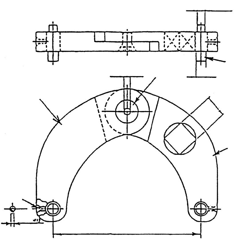
7/32" (5.556) 3 4
5/16 DIA. (7.938) D3/4" (19.05)
1
5
3/32" (2.381) MIN.2" - MAX.6" (50.8 - 152.4)
Component parts No. Part name Q'ty Remarks 1 Arm 1 Each drive 3/4" 2 Arm 1 3 Center pin 1 4 Pin 2 Diameter 1/4", 5/16" 5 Set screw 2

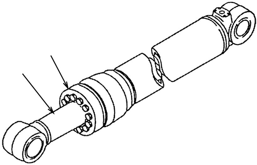
[2] Piston ring expander
Characteristics
A teflon ring is used on the piston of the hydraulic cylinder, but this cannot be installed as is.
By simply rotating the handle, the ring expander can be used to expand the ring smoothly and easily for mounting on the piston without creating any damage.
With the use of a compression ring, the teflon ring to be installed on the piston can be mounted exactly at the specified position. [3] Bushing tool kit
Part No.: KRV10630
Application: Each bushing tool can be installed to the grip by bolts and be used as striking tool when press fitting the wrrapping bearing on the attachment cylinder.
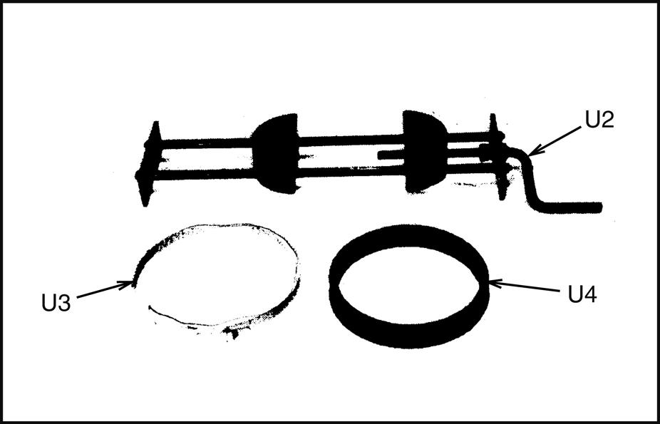
Component parts Tool Part name Part No. Q'ty Remarks U2 Expander KRV10570 1
U3 Clamp KRV10600 1 Piston outer diameter φ120 - φ135 KRV10610 1 Piston outer diameter φ100 - φ115
U4 Ring (rubber band) KRV10580 1 Piston outer diameter φ120 - φ135 KRV10590 1 Piston outer diameter φ100 - φ115
(6) Disassembly procedures [1] Piston rod assembly a.Remove the line from the cylinder assembly. b.Remove the installation bolts and separate the head assembly (1). c.Remove the piston rod assembly (2). •Place a drip pan or other object under the cylinder to receive the oil.
d.Disassemble the piston rod assembly with the procedure below. 1.Set the piston rod assembly (2) on the stand (*1).
2.Remove the piston assembly rotation stopper screw (3). •If the screw (3) caulking is so strong the screw cannot be removed, screw the screw all the way in and then insert the tap (*2) in the threaded section and try to remove the screw.


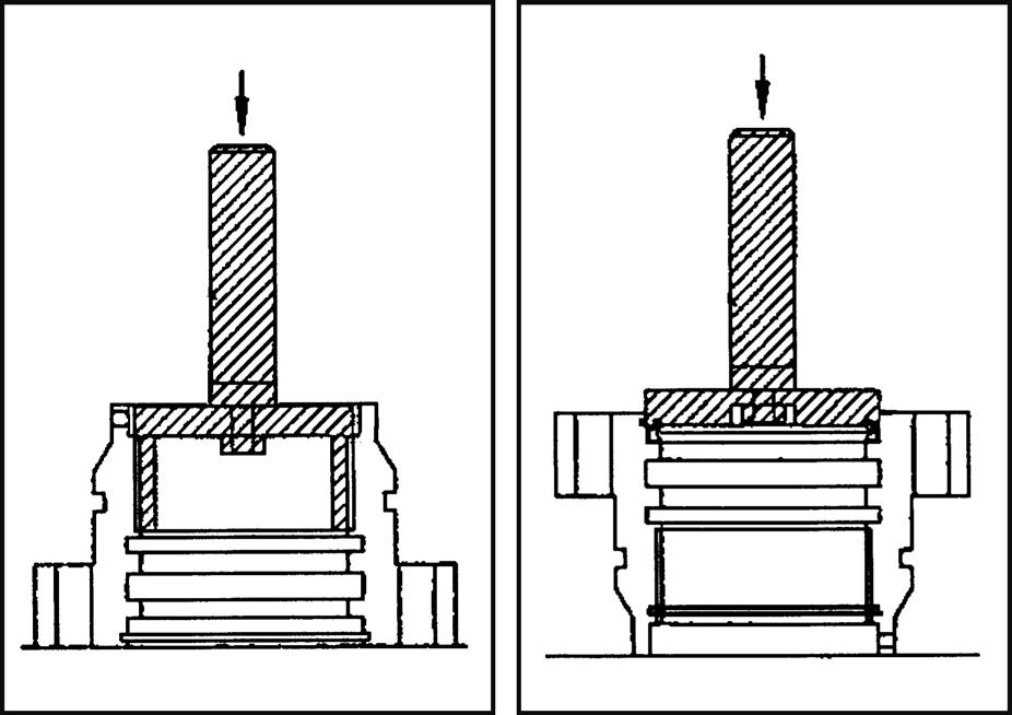
3.Use tool U1 to remove the piston assembly (4). •When not using tool U1, use the 2 notch holes (φ10) (*3) to loosen the piston assembly.
4.Remove the plunger (5). •Boom cylinder •Arm cylinder •Bucket cylinder 5.Remove the collar (6). •Boom cylinder •Arm cylinder •Bucket cylinder 6.Remove the head assembly (7).
7.Remove the cap (8), remove the 12 balls (9), and then remove the cushion plunger (10). •Arm cylinder
[2] Disassembly of piston assembly a.Remove the rings (11). b.Remove the wear rings (12). c.Remove the piston ring (13). d.Remove the O-ring and backup ring (14).
[3] Disassembly of cylinder head assembly a.Remove the O-ring and backup ring (15). b.Remove the snap ring (16), and then remove the dust seal (17). c.Remove the rod packing (18). d.Remove the buffer ring (19). e.Remove the snap ring (21). f. Remove the bushing (20).


(7) Assembly procedures •Be careful not to scratch the packing, dust seal, or O-ring. •Insert the buffer ring after heating with hot water at about 50℃ - 60℃ without forcing it in. [1] Assembly of piston rod assembly a.Use a tool to press fit the bushing (20) and install the snap ring (21). b.Install the buffer ring (19). c.Install the rod packing (19). d.Use a tool to install the dust seal (17) and secure with the snap ring (16). e.Install the backup ring and O-ring (15).
[2] Assembly of piston assembly a.Use tool U2 to widen the piston ring (13). •Set the piston ring on tool U2 and widen the piston ring by rotating the handle 8 - 10 times. b.Set tool U3 and retract the piston ring (13).
c.Install the backup ring and O-ring (14). d.Install the wear rings (12). e.Install the rings (11). •Be careful not to widen the ring abutment section too much. Ring groove: grease (G2-L1)

[3] Piston rod assembly a.Set the piston rod assembly (2) on the stand (*1).
b.Install the head assembly (7). c.Attach the O-ring and backup ring to the collar (6) and install it. •Boom cylinder •Arm cylinder •Bucket cylinder d.Install the plunger (5). •Boom cylinder •Arm cylinder •Bucket cylinder •Check that the top of the plunger has slight backlash. e.Set the cushion plunger (10) on the piston rod, install the 12 balls (9), and then secure with the cap (8). •Arm cylinder only f. Assemble the piston assembly (4) with the procedure below. •When reusing the rod and piston assembly (4)
Thoroughly clean and remove all shavings and debris. 1.Screw in the piston assembly (4) and use tool U1 to tighten the piston assembly (4) until it matches the position of the screw threaded hole. •Use a file to remove burrs and barbs. 2.Tighten the screw (3). Tightening torque: 66.2 ± 7.35 N•m

3.Use a punch (*2) to caulk the threaded section at 4 locations. •When using new parts for the rod and/or piston assembly (4) Mark the cushion plug position on the end surface of the rod with bottom cushion. •Arm cylinder only
4.Screw in the piston assembly (4) until it touches the end surface of the rod, and use tool U1 to tighten the piston assembly.
Tightening torque: 294 ± 29.4 N•m •After tightening the piston, check that the plunger (5) has backlash. •Boom cylinder •Arm cylinder •Bucket cylinder 5.Create a threaded hole for mounting the screw (3). •Align the drill of the V groove on the threaded section of the rod (2) with the piston (4) and create a threaded hole horizontally. •Create a threaded hole on the cylinder with bottom cushion (arm cylinder) while avoiding the position of the cushion plug.
6.After creating holes, thoroughly clean and remove all shavings and debris. 7.Tighten the screw (3).
Tightening torque: 66.2 ± 7.35 N•m 8.Use a punch to caulk the threaded section at 4 locations.
Threaded hole dimensions (mm)
Cylinder type
Drill diameter of bottom hole Depth of bottom hole Used tap Depth of tap
Boom bucket 10.3 36 12×1.75 29 Arm 10.3 43 12×1.75 36


g.Install the piston rod assembly (2).
Ring groove: grease (G2-L1) •Set the ring abutment section (*3) at a horizontal position and insert the ring abutment section while aligning the cylinder tube and shaft. •After inserting, check that the ring is not damaged or fallen out, and push it all the way in. h.Tighten the head assembly (1) with installation bolts.
i. Install the line.
Installation bolt tightening torque
Cylinder name Tightening torque Boom
Arm 1275 ± 196 N•m
Bucket 892 ± 137 N•m

