
24 minute read
Procedures for Assembly and Disassembly of Control Valve


1.Assembly and disassembly precautions (1) General precautions [1] As hydraulic equipment has been manufactured with a high degree of precision and contains small gaps, perform assembly and disassembly in a clean location with little dust. Use only clean tools and cleaning oil and handle them with sufficient care. [2] When the control valve is removed from the actual machine, thoroughly clean the areas around line ports and insert plugs to take every precaution to prevent any entry of dust or water. Also when installing the control valve on the actual machine, do not remove plugs until lines have been installed. [3] Study the structure diagram before starting work and prepare the parts required by the objective and scope. Also, some parts have to be replaced as part of a subassembly because they cannot be supplied as single parts, so consult the parts list in advance to prepare for this. (2) Disassembly [1] Each part has been manufactured with a high degree of precision, so be careful not to let parts bump each other or fall when handling them. [2] If parts are struck or pried off with excessive force during work because they are tight, this may cause burrs, damage or faulty assembly which may then cause oil leaks or reductions in performance. Perform work carefully. [3] Use identification tags to reassemble parts correctly by returning them to their original position after disassembly. [4] Do not reuse disassembled O-rings and backup rings. (Remove them with a wire that has a shoe horn-shaped end and be careful not to scratch the groove section at this time.) [5] Rust may form on parts due to moisture or debris if they are left disassembled or if work is abandoned in the middle of assembly. If a pause in the work is unavoidable, be careful to prevent rust and keep off dust. (3) Assembly [1] Observe the same cautions as with disassembly. [2] When performing assembly, remove metal fragments and foreign matter from parts, and check that there are no burrs or nicks on parts. If there are burrs or nicks, use a whetstone to remove them. [3] Replace O-rings and backup rings with new ones. [4] When installing O-rings and backup rings, be careful not to damage them. (Apply a thin layer of grease to ensure smooth installation.) [5] Tighten bolts and caps to the specified torque.
2.Replacing the main plunger
The main plunger was selected to fit with the housing, so this part should not be serviced. Accordingly, be aware that this part, as a rule, cannot be replaced at the worksite. [1] If for some reason this part is to be replaced, contact us with the part code and manufacturing number etched into the nameplate or the distinguishing color. [2] The distinguishing color is painted on the surface of the cast body of the housing (top right or top left) with fitting holes. When the paint is peeled off, the distinguishing color becomes visible.
3.Accessories (1) Holder Material: brass

(2) Cap assembly
Material: steel (Hexagon diameter: 19)
(3) Cap
Material: steel


4.Valve separation and linked work

(1) Disassembly [1] Remove the hexagon socket head bolts ① and ④ , and remove the 4-valve side block. [2] Remove the hexagon socket head bolts ② and ③ , and remove the 5-valve side block. •Hexagon socket head bolt Hexagon diameter: 14 (2) Assembly
Stand up the valve assembly on a flat surface, first install the 5-valve side block on the manifold, and tighten the bolts to the specified torque. Next, install the 4-valve side block. •Hexagon socket head bolt
Hexagon diameter: 14
Tightening torque: 245 N•m •Check that the O-ring is properly mounted on the installation surface of the manifold.
5.Main plunger section
This section explains the disassembly procedure. To assemble, perform the reverse of the disassembly procedure.
Manage the parts with shipping tags so that they are reassembled properly.
[1] Remove the hexagon socket head bolt (1) and remove the cover (2). •Hexagon socket head bolt
Hexagon socket diameter: 10
Tightening torque: 98 N•m •Before installing the cover for reassembly, confirm that there is an O-ring mounted at the housing opening. [2] Remove the plunger as a subassembly. •During reassembly, align the key groove positions on the rotation stopper plunger and insert. •Do not remove the plunger all at once. Slowly rotate it while checking the states of contact with the housing to remove it.
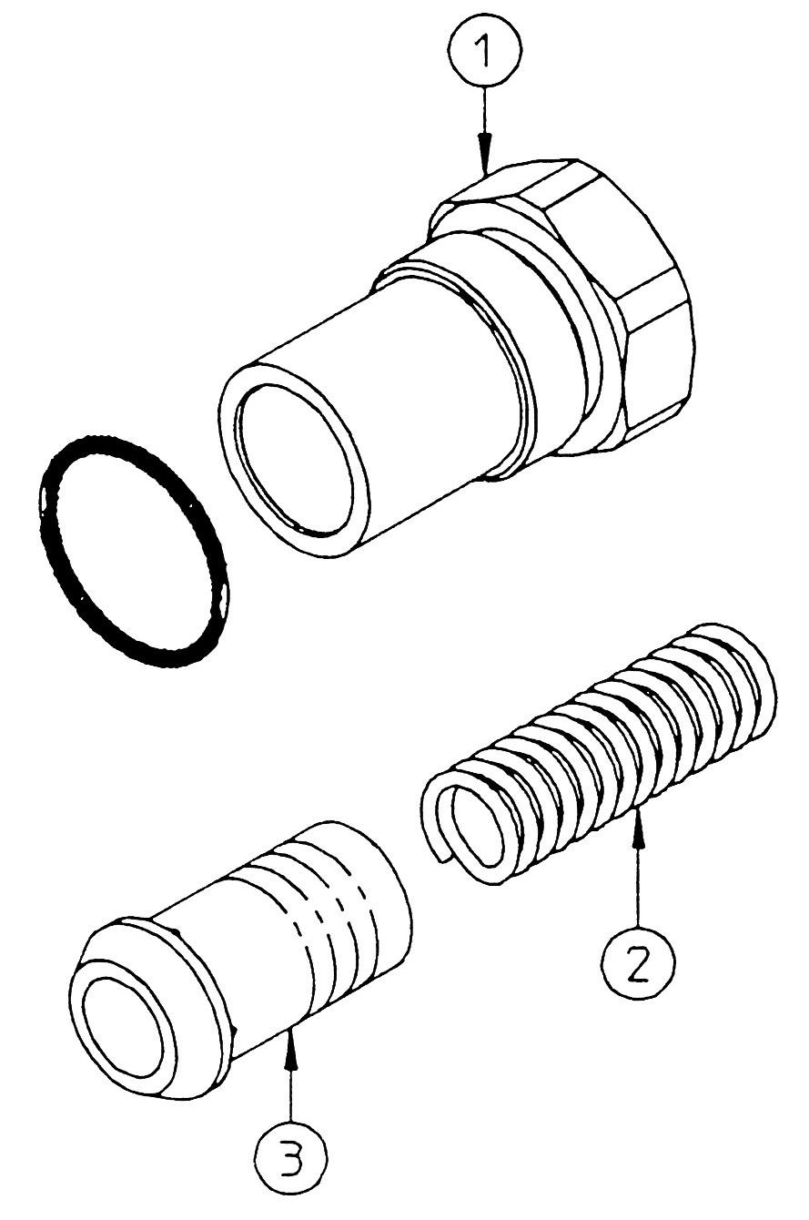
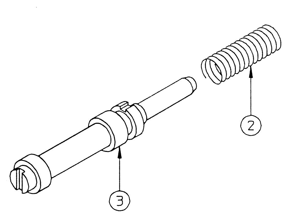
[3] Hold the plunger stationary with a tool (holder) and then hold the plunger using a vice and loosen the plunger cap (3). •Plunger cap
Hexagon socket diameter: 10
Tightening torque: 98 N•m •Sufficiently degrease both the plunger and holder.


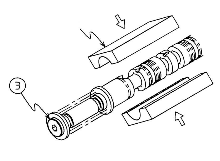
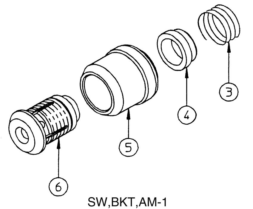
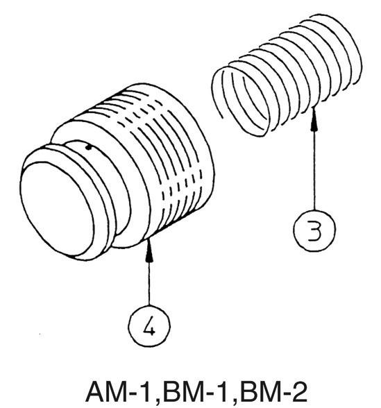
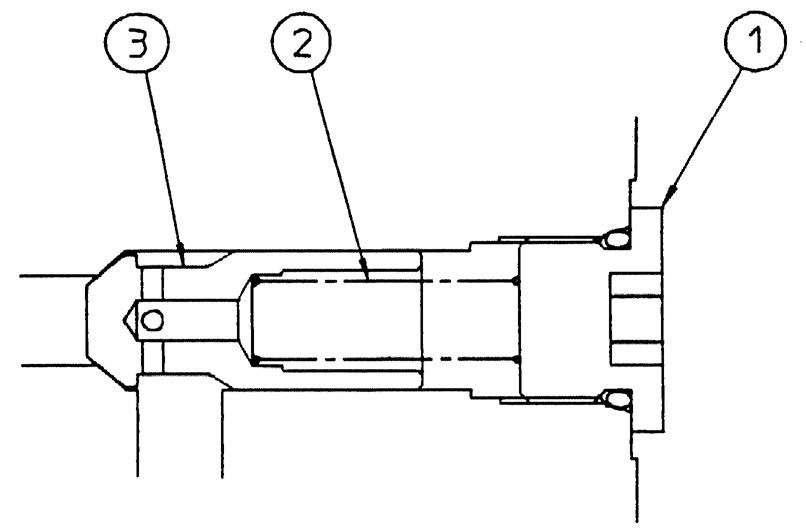
[4] Remove the plunger cap (3) and remove the spring guides (4), spring (5) and sleeve (6). •The straight travel plunger has different spring, so use caution.
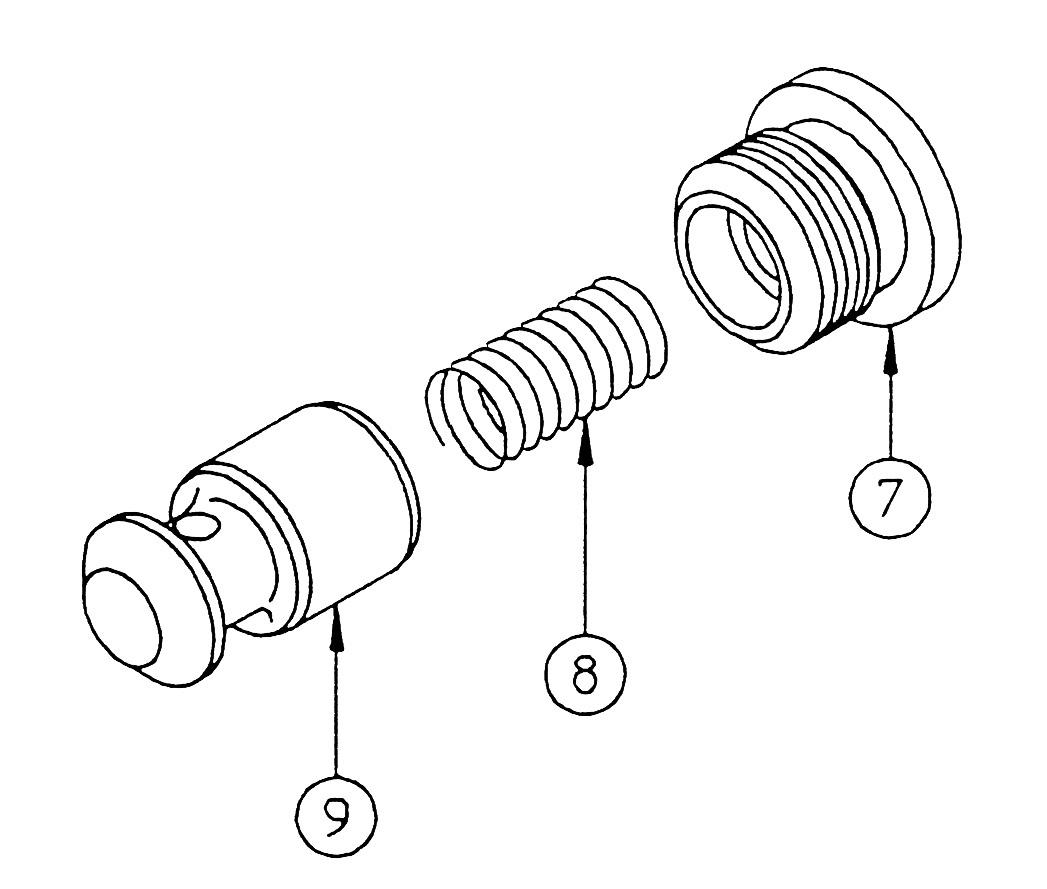
[5] Remove the caps (7) on the opposite side of the BM-1 and AM-1 plungers only, and remove the spacer (8), spring (9) and check (10). •Cap
Hexagon socket diameter: 8
Tightening torque: 59 N•m


6.Center bypass valve
This section explains the disassembly procedure. To assemble, perform the reverse of the disassembly procedure. • During disassembly, manage each part with shipping tags so that they are reassembled properly.
[1] Remove the cap (1), and remove the spool (3) and spring (2). •Cap
Hexagon diameter: 46
Tightening torque: 245 N•m •Cap A is not attached to the 5-valve block side.


7.Check valve
This section explains the disassembly procedure. To assemble, perform the reverse of the disassembly procedure. •During disassembly, manage each part with shipping tags so that they are reassembled properly.
Explanation is given using the AM-2 [double check] as an example.
[1] Remove the cap (1), and remove the spring (2) and checks (3) and (4). •Cap
Hexagon socket diameter: 14 Tightening torque: 343 N•m Same for all locations


8.Priority
This section explains the disassembly procedure. To assemble, perform the reverse of the disassembly procedure. •During disassembly, manage each part with shipping tags so that they are reassembled properly. [1] Remove the hexagon socket head bolt (1) and remove the cover (2). •Hexagon socket head bolt Hexagon socket diameter: 12 Tightening torque: 176.5 N•m
[2] Remove the spring (3), spring guide (4), sleeve (5) and poppet subassembly (6). •The poppet orifice diameter varies for each. •Make sure to reassemble in the original location.

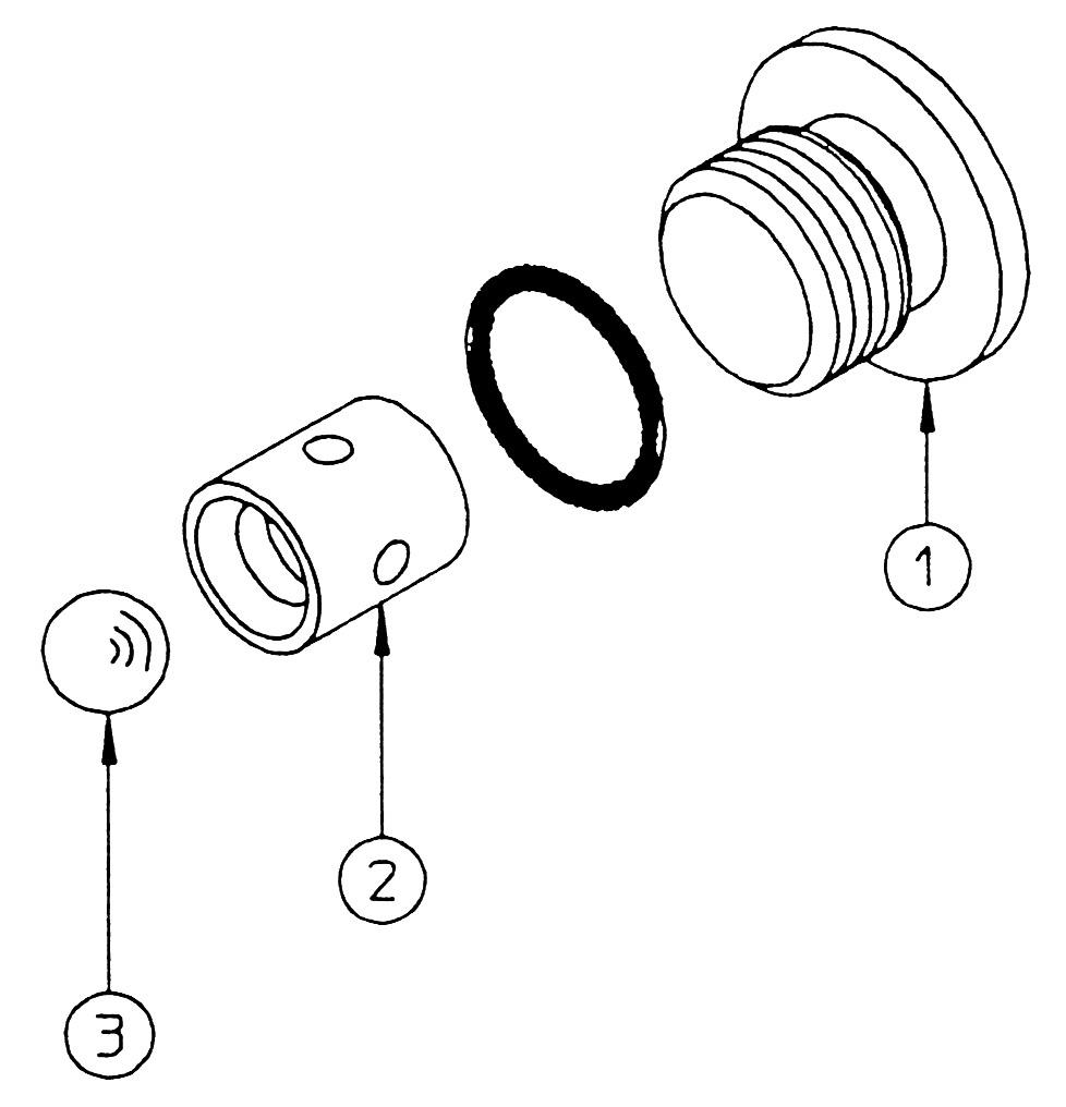
[3] Use a tool (holder) to gently secure the poppet subassembly (6), hold using a vice and remove the cap (7), and remove the spring (8) and check (9). •Cap
Hexagon socket diameter: 6
Tightening torque: 34.5 N•m
•Sufficiently degrease both the poppet and holder. •Be careful as the poppet orifice diameter varies.


[4] Remove the cap (10) and use a soft rod with a diameter of φ8 to φ9 to remove the plate (11), spring (12), and piston (13) while tapping with a hammer. •Cap
Hexagon socket diameter: 5
Tightening torque: 19.5 N•m •The spring has a reactive force. Make sure that parts do not fly off when the plate comes off.

9.Inspection and handling
Clean each part with pure cleaning oil, and dry each part with compressed air or a soft short-haired fabric. Parts are easy to mix up and lose, so keep parts organized to make work go smoothly.
External shape inspection
1.Housing
Perform a visual inspection for scratching, rust and corrosion. Also, inspect the insides using a testing agent. * As the valve housing is a part that is not serviced, replace the control valve assembly when there is damage that cannot be repaired.
2. Plunger 1)Perform a visual inspection for scratching, seizing, rust and corrosion. *If there is scratching on the outer circumference of a plunger, reinspect the fitting hole. 2)Insert the plunger into the housing hole and slide it forward and backward while rotating it. 3)Check for damage on the check seat section and check valve inside the plunger.
4)Insert the plunger into the check valve and slide it forward and backward by hand. Judgment criteria and solution ・ Use #2000 sandpaper or a whetstone to repair dents, scratching, rusting, or corrosion. ・ In the case of damage to any of the areas below, repair cannot be done. 1)Housing hole: plunger sliding parts or, in particular, parts that receive holding pressure 2)Seat section: check valve seat surface 3)Port seal section: O-ring touching section 4)Seal section of each hole, such as main relief and overload relief 5)Other damage judged to be a hindrance to normal functioning
・ Use #2000 sandpaper or a whetstone to repair dents, scratching, rusting, or corrosion. ・ If there is a scratch on the sliding section of the outer circumference that a finger nail could catch on, there is a defect.
・ Smooth movement means there is no problem.
・ If there is scratching or wear on a seat section, repair or replacement is necessary, otherwise the seal will become defective. ・ Light, smooth movement without catching means there is no problem.
5)Inspect regardless of whether there is a spring abnormality or not. 3. Return spring, packing section
Inspect for rust, corrosion, wear, deformation and damage on the springs, spring guides, plunger caps and covers. 4. Load check valve, each check valve 1)Inspect for scratches on the check seat section.
2)Inspect for spring abnormalities. 5. Orifice section
Inspect whether there is something clogging the orifice of the valve block or foot relief valve. ・ Replace if damage or scratching is discovered, as this indicates a defect.
・ Replace if there is wear or deformation that cannot be repaired.
・ If there is scratching or wear on a seat section, repair or replacement is necessary, otherwise the seal will become defective. ・ Replace spring if there is damage or abnormal scratching.
・ If there is something causing clogging, remove it with a wire.
6. Shuttle valve
Inspect the shuttle seat surface for damage. ・ If there is scratching or wear on a seat section, repair or replacement is necessary, otherwise the seal will become defective.
External shape inspection Judgment criteria and solution 7. Load holding valve, priority valve, regeneration valve 1)Inspect the poppet seat surface for damage.
2)Insert the poppet into the sleeve and move it forward and backward. ・ If there is scratching or wear on a seat section, repair or replacement is necessary, otherwise the seal will become defective. ・ Smooth movement means there is no problem.
8. Main relief valve, overload relief valve 1)Inspect each seat section for damage. 2)Inspect whether there is something clogging the orifice holes. 3)Insert the poppet and move it. 4)Inspect for spring abnormalities. 5)Visual inspection of whether the relief valves (main relief valve, overload relief valve) are in an acceptable state is possible, but further inspection is difficult. For checking functions, judgment can be done by sufficiently inspecting the operation status. ・ If there is scratching or wear on a seat section, repair or replacement is necessary, otherwise the seal will become defective. ・ If there is something causing clogging, remove it with a wire. ・ Smooth movement means there is no problem. ・ Replace spring if there is damage or abnormal scratching.
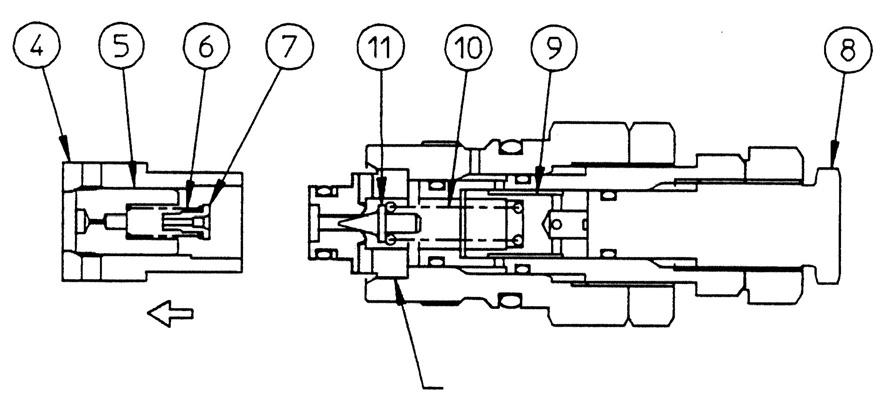
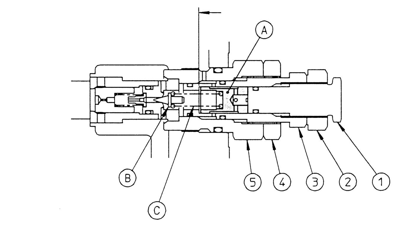
10.With load holding valve AM-1, BM-1, BM-2
This section explains the disassembly procedure. To assemble, perform the reverse of the disassembly procedure. •During disassembly, manage each part with shipping tags so that they are reassembled properly.
[1] Main unit check valve 1) Remove the hexagon socket head bolt (1) and remove the cover assembly (2). •Hexagon socket head bolt Hexagon socket diameter: 12 Tightening torque: 176.5 N•m •Before installing the cover for reassembly, confirm that there is an O-ring mounted on the cover matching surface. 2) Remove the spring (3) and poppet (4).

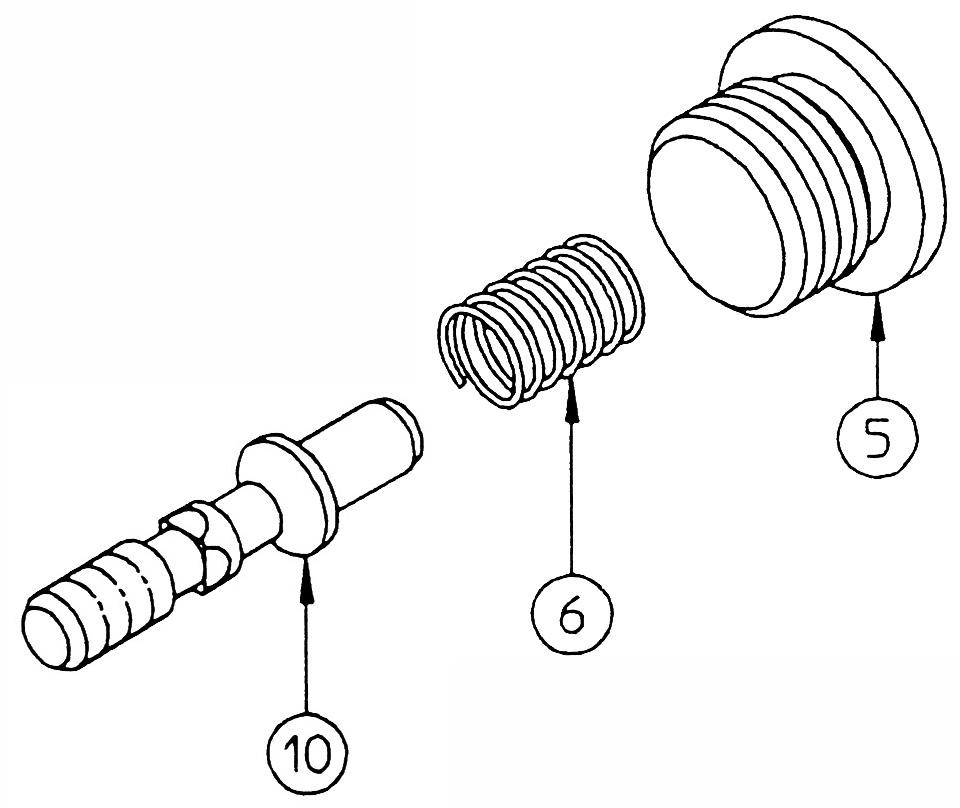
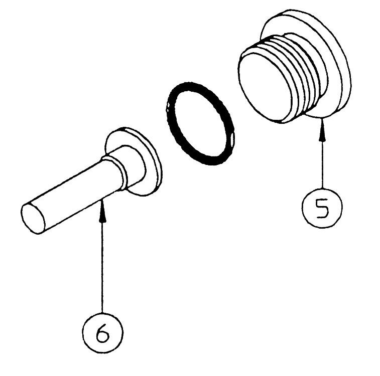
[2] Cover section 1) Remove the cap (5), and remove the spring (6) and poppet (10). •Cap Hexagon socket diameter: 10 Tightening torque: 49 N•m •For parts that have been in operation for a long time, the poppet (10) may not be able to be removed from the edge of the sleeve (9) seat surface. Do not force disassembly of parts. 2) Remove the cap (7) and remove the piston (8). •Cap Hexagon socket diameter: 10 Tightening torque: 49 N•m 3) Use a pipe with an inner diameter of φ10 and an outer diameter of φ14 and lightly tap out the sleeve (9) from the left side.

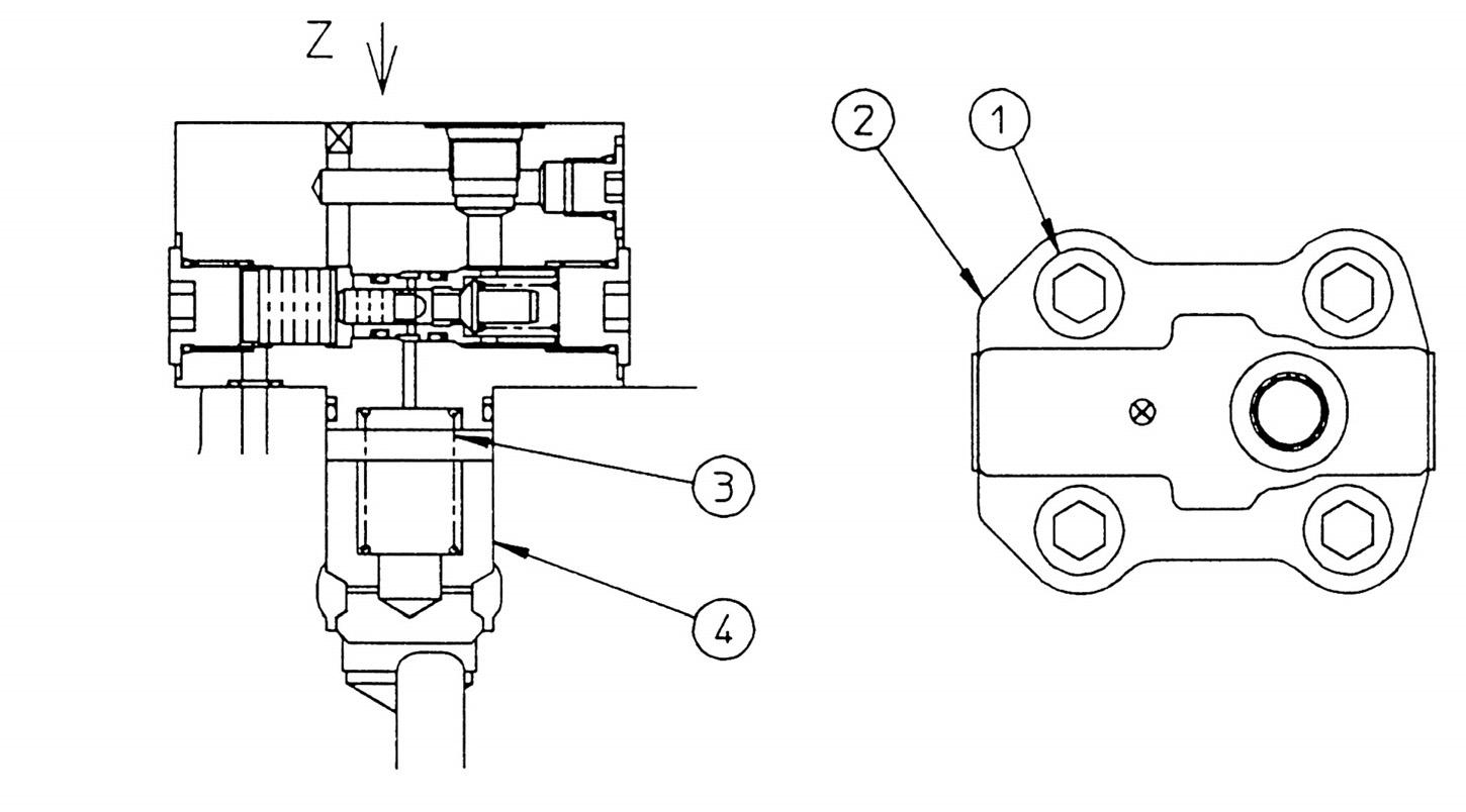
11.Cover section [PL rotation stopper]
This section explains the disassembly procedure. To assemble, perform the reverse of the disassembly procedure. •During disassembly, manage each part with shipping tags so that they are reassembled properly.
[1] Remove the hexagon socket head bolt (1) and remove the cover (2). •Hexagon socket head bolt
Hexagon socket diameter: 10
Tightening torque: 98 N•m •Before installing the cover for reassembly, confirm that there is an O-ring mounted at the housing opening. [2] Remove the plug (3). •Plug
Hexagon diameter: 19
Tightening torque: 78.5 N•m

12.Arm regeneration valve, end bucket, and confluence check section
This section explains the disassembly procedure. To assemble, perform the reverse of the disassembly procedure. •During disassembly, manage each part with shipping tags so that they are reassembled properly.

[1] Arm regeneration valve 1) Remove the sleeve (1), and remove the spring (2), spool (3) and piston (4). •Sleeve Hexagon diameter: 46 Tightening torque: 176.5 N•m •When the sleeve comes off, there is slight reactive force from the spring. Remove the sleeve while pressing.
2) Remove the cap (5) and remove the spring guide (6). •Cap
Hexagon socket diameter: 12
Tightening torque: 98 N•m

[2] BKT confluence check section 1) Install the removal cap. 2) Activate the actual machine and operate the BKT plunger 1 or 2 times. (The sleeve comes off at this time.) 3) Stop the actual machine and remove the cap, sleeve (7), spring (8), and check (9).

13.Foot relief valve
This section explains the disassembly procedure. To assemble, perform the reverse of the disassembly procedure. •During disassembly, manage each part with shipping tags so that they are reassembled properly.
[1] Remove the cap (1), and remove the spring (2) and poppet (3). •Cap
Hexagon diameter: 46
Tightening torque: 245 N•m

14.Straight travel switchover pilot section
This section explains the disassembly procedure. To assemble, perform the reverse of the disassembly procedure. •During disassembly, manage each part with shipping tags so that they are reassembled properly.
(1) Remove the cap (1), and remove the spring (2) and spool (3). •Cap
Hexagon socket diameter: 6
Tightening torque: 29.5 N•m

15.Orifice section
This section explains the disassembly procedure. To assemble, perform the reverse of the disassembly procedure. •During disassembly, manage each part with shipping tags so that they are reassembled properly. •Cap
Hexagon socket diameter: 6
Tightening torque: 29.5 N•m
[1] Remove the cap ① and install the removal tool cap assembly. [2] Screw in the hexagon socket head bolt to the top of the orifice, and while holding the hexagon socket head bolt, rotate the hexagon bolt and remove the orifice. •Cap
Hexagon socket diameter: 6
Tightening torque: 29.5 N•m
Reassembly
Screw in the hexagon socket head bolt to the top of the orifice and hit it in with a hammer.


16.Check valve (for straight travel)
This section explains the disassembly procedure. To assemble, perform the reverse of the disassembly procedure. •During disassembly, manage each part with shipping tags so that they are reassembled properly.
(1) Remove the cap (1), and remove the spring (2) and check (3). •Cap
Hexagon socket diameter: 8
Tightening torque: 39 N•m

17.Shuttle valve
This section explains the disassembly procedure. To assemble, perform the reverse of the disassembly procedure. •During disassembly, manage each part with shipping tags so that they are reassembled properly.
(1) Remove the cap (1), and remove the shuttle seat (2) and steel ball (3). •Cap
Hexagon socket diameter: 6
Tightening torque: 29.5 N•m •Shuttle seat
Cap side inner diameter: M5

18.Relief valve (1) Procedures for assembly and disassembly of main relief valve [1] Disassembly 1) Loosen the cap (1) and remove the cartridge as is. Hexagon diameter: 41
2) Loosen the hexagon nut (2).
Hexagon diameter: 41

3) Loosen the hexagon nut (3). (Hexagon diameter: 30) 4) Pull out the sleeve (4) and remove the main poppet (5), spring (6), and orifice (7). •Do not disassemble the pilot seat as it is press fit to the cap.
5) Remove the adjusting screw (8), piston (9), spring (10), and pilot poppet (11). •Adjusting screw
Hexagon diameter: 22


[2] Assembly and pressure setting
•If a mistake is made with the relief valve set pressure, this can damage hydraulic devices or invite danger. Never raise pressure above the set amount for each model. 1) Temporary assembly and setting 1.Tighten the adjusting screw (1) until the piston (A) touches the Z surface of the sleeve (3). 2.Check the set pressure "0" position. After facing the adjusting screw side down and first loosening the sleeve (3), screw it in again and temporarily set the position where the pilot poppet (B) touches the seat section, namely the point where the pressure adjustment spring (C) begins to take effect. 3.Install the temporarily assembled cartridge to the main unit and tighten the cap (5). Tightening torque: 98 N•m 2) High-pressure setting 1.Install an accurate pressure gauge in the hydraulic pump discharge port. 2.Run the pump at its rated rotation rate. 3.Move the BM-UP, AM, or BKT plunger through its full stroke and read the pressure gauge. 4.Rotate (right rotation) the sleeve (3) and adjust pressure while watching the pressure gauge. 1/4 of a rotation changes the pressure about 4.5 MPa. •The sensitivity of relief is very strong, so do not suddenly tighten the relief valve for any reason. 5.Secure the sleeve (3) after pressure setting, and tighten it with the hexagon nut (4). Tightening torque: 98 N•m •Operate the plunger and check the set pressure. 3) Low-pressure setting 1.After the above mentioned high-pressure setting, adjust the pressure while loosening the adjusting screw (1) (left rotation). 2.Secure the adjusting screw (1) after pressure setting, and tighten it with the hexagon nut (2). •Operate the plunger and check the set pressure.
(2) Procedures for assembly and disassembly of overload relief valve
This section explains the disassembly procedure. To assemble, perform the reverse of the disassembly procedure. •During disassembly, manage each part with shipping tags so that they are reassembled properly. •As pressure adjustment with the actual vehicle is difficult, do not disassemble the pressure adjustment section. •Make sure to reassemble in the original location. [1] Loosen the sleeve (1) and remove the cartridge as is. •Cap Hexagon diameter: 41 Tightening torque: 98 N•m
[2] Loosen the cap (2), remove the subassembly as is, and remove the spring (3) and the pilot poppet (4). •Cap
Hexagon diameter: 32
Tightening torque: 98 N•m


[3] Remove the pilot seat (5), springs (6) and (7), piston (8), and the main poppet (9).

19.Troubles and countermeasures
Control valves overall
Trouble content
The spool does not move through its stroke.
The load cannot be held.
When the spool is switched from the neutral to the raise position, the load falls. Conceivable cause Countermeasure
1. The oil temperature is abnormally high. Eliminate the section that is providing resistance to the oil flow in the line.
2. Dirty hydraulic oil
Replace the hydraulic oil and at the same time, clean the circuits. 3. Line port joint tightened too much Check the torque. 4. The valve housing was warped during installation. Loosen the installation bolts and check. 5. The pressure is too high. Attach a pressure gauge to the pump and the cylinder port and check the pressure.
6. The spool is bent. Replace the spool as an assembly.
7. Return spring damage
Replace the damaged part. 8. The spring or cap is out of place. Loosen the cap, center it, then tighten it. 9. The temperature distribution within the valve is not uniform. Warm up the circuits as a whole. 10.Debris is clogging inside the valve. Remove (flush out) the debris. 11.Pilot pressure insufficient Inspect for the pilot valve and pilot relief pressure.
1. Oil leak from cylinder Check the cylinder seal section. 2. Oil from the spool is bypassing. Check for spool damage. 3. Oil leak from overload relief valve Clean the valve housing seat section and relief valve seat section. 4. Oil leak from antidrift valve Disassemble the antidrift valve and clean the seat section for each part. If a seat section is damaged, replace the poppet or lap the poppet and seat section. If the antidrift valve spool is abnormal, since the spool and the sleeve are mating parts, replace them both at the same time.
1. There is debris jammed in the load check valve. Disassemble and clean the check valve.
2. The check valve poppet or seat section is damaged. Replace the poppet or lap the poppet and seat section.
Relief valve
Trouble content
Pressure does not rise at all.
The relief pressure is unstable.
The relief pressure is wrong.
Oil leak Conceivable cause
1. Either the main poppet, sleeve, or pilot poppet is stuck open or there is debris jammed in the valve seat section. Countermeasure
Replace the relief valve.
1. The pilot poppet seat section is damaged. 2. The piston or main poppet is stuck. 1. Seat section worn by debris 2. The lock nut and adjuster are loose. Set the pressure again, then tighten the lock nut to the specified torque. 1. Relief valve seat section damage Replace the relief valve. 2. Each part is stuck due to debris. 3. An O-ring is worn. Replace the adjuster or installation section Oring.
Hydraulic system overall
Trouble content Conceivable cause Countermeasure
The hydraulic system is not working properly or is not working at all. 1. Pump trouble Check the pressure or replace the pump.
2. Relief valve trouble Replace the relief valve.
3. Cylinder trouble
Repair or replace. 4. Pump load pressure is high. Check the circuit pressure. 5. There is a crack in the valve. Replace the valve as an assembly. 6. The spool does not move through its full stroke. Check the spool movement. 7. The tank oil level is too low. Fill the hydraulic oil. 8. The filter in the circuit is clogged. Clean or replace the filter. 9. The circuit line is throttled. Check the line.
External shape diagram
a Main unit lifting tap (M16) b Arm (1) out c Boom (2) down d Option e Swing right f Left travel forward g Arm (1) in h Boom (2) up i Swing left j Left travel backward k Arm (2) in l Boom (1) up m Bucket close n Right travel backward o Arm (2) out p Boom (1) down q Bucket open r Right travel forward
Internal structure diagram 1

Code Part name Q'ty Code Part name Q'ty 1 Housing 1 42 Spring 1 2 Plunger G assembly 1 43 Piston 1 3 Plunger M3 assembly 1 44 Cover 1 4 Plunger C3 assembly 1 45 Socket head bolt 4 5 Plunger B15 assembly 1 46 Cap 1 6 Plunger D9 assembly 1 47 O-ring 1 7 Socket head bolt 20 48 Cap 1 8 Cover 5 49 Spring 1 9 Cap 2 50 Spool CB 1 10 O-ring 2 51 Flange 2 11 O-ring 10 52 O-ring 2 12 Foot relief assembly 1 53 Cover 1 13 O-ring 2 54 Socket head bolt 4 14 O-ring 8 55 Cap 2 15 Plug MR 1 56 O-ring 2 16 Cover 3 57 O-ring 1 17 Plug 2 58 Sleeve 1 18 O-ring 6 59 Poppet 1 19 Cap 3 60 Spring 1 20 Cap 1 61 Backup ring 1 22 Cover 2 62 O-ring 1 23 Poppet 1 63 Backup ring 1 24 Spring 1 64 Piston 1 25 O-ring 2 65 Spring 1 26 Backup ring 2 66 Spool TS 1 27 Cover 1 67 Socket head bolt 8 28 Socket head bolt 12 68 Washer CD 8 29 Spring washer 8 69 Main relief assembly 1 30 Backup ring 1 70 Overload assembly 4 31 O-ring 11 71 O-ring 4 32 Cap 1 72 Backup ring 4 33 Spring 1 73 O-ring 4 34 Check valve 1 74 Cap 1 35 Poppet 1 75 Check valve 1 36 Sleeve 1 76 Spring 4 37 Guide SP 1 77 Check valve 4 38 Spring 1 78 Backup ring 6 39 O-ring 1 79 Cap 3 40 Backup ring 1 80 Cap 1 41 Plate 1
Internal structure diagram 2

Code Part name Q'ty Code Part name Q'ty 1 Housing 1 44 Cover 2 2 Plunger M3 assembly 1 45 Socket head bolt 8 3 Plunger T7 assembly 1 46 Spring washer 8 4 Plunger D10 assembly 1 47 Cap 4 5 Plunger D11 assembly 1 48 O-ring 4 6 Plunger A12 assembly 1 49 O-ring 2 7 Socket head bolt 20 50 Backup ring 2 8 Cover 3 51 O-ring 2 9 Cap 1 52 Poppet 2 10 O-ring 2 53 Spring 2 11 O-ring 10 54 Sleeve 2 12 O-ring 2 55 Poppet 2 13 Foot relief assembly 1 56 Spring 2 14 Cover 5 57 Cap 6 15 Cap 1 58 Backup ring 2 16 Cover 2 59 O-ring 2 17 Plug 2 60 Backup ring 2 18 O-ring 10 61 Piston 2 19 Backup ring 2 62 Socket head bolt 4 20 O-ring 2 63 Washer CD 4 21 Cap 2 64 Orifice 1 22 Spring 2 65 Steel ball 1 23 Check valve 2 66 Shuttle seat 1 25 Sleeve 2 67 Spring 1 26 Guide SP 2 68 Spool TS 1 27 Spring 2 69 Orifice 1 28 O-ring 2 70 Overload assembly 2 29 Backup ring 2 71 O-ring 2 30 Plate 2 72 Backup ring 4 31 Spring 2 73 O-ring 2 32 Piston 2 74 Cap 2 33 Cover 2 75 O-ring 2 34 Socket head bolt 8 76 Cap 2 35 Cap 2 77 Spring 3 36 O-ring 2 78 Check valve 3 37 Poppet 2 79 Backup ring 3 38 Cap 1 80 O-ring 3 39 Spring 1 81 Cap 1 40 Spool CB 1 83 Cap 1 41 Flange 2 84 O-ring 1 42 O-ring 2 85 Plug 2 43 Socket head bolt 8 86 O-ring 2
