
11 minute read
Procedures for Assembly and Disassembly of Regulator


1.Tools
The table below shows the tools required for the assembly and disassembly of KR3G-9*04-HV.
Tool name and dimensions
Required tools are indicated with ○ Part name
Name B Hexagon socket head bolt (shouldered bolt) Rc mounted valve (Rc screw) ROH plug (G screw)
Hexagon socket head locking screw 2 - - - M4
Hexagon wrench 2.5 - - - M5 3 - - - M6 4 M5 BP-1/16 - M8 5 M6 BP-1/8 - M10 6 M8 BP-1/4 RHO-1/4 M12 M14 8 M10 BP-3/8 RHO-3/8 M16 M18 10 M12 BP-1/2 RHO-1/2 M20 12 M14 - - 14 M16 M18 BP-3/4 RHO-3/4 17 M20 M22 BP-1 RHO-1 19 M24 M27 - - -
22 - - VP-3/8 24 M16 M16 27 M18 M18 VP-1/2 -
Closed wrench Socket wrench Double-head wrench Single-head wrench 30 ○ M20 M20 36 - - VP-3/4 41 - - VP-1 -
46 M30 M30 - 50 - - VP-11/4 55 - - VP-11/2 Monkey wrench - ○ Medium-sized × 1 Screwdriver - ○ Medium-sized flathead screwdriver × 1
Pliers
- ○ For stop ring, TSR-160 - ○ For locking ring, TRR-150 Torque wrench - ○ Wrench capable of specified torque tightening Steel rod - ○ Diameter φ4 or less L = 100 Hexagon socket head bolt - ○ M4 for pulling out adjusting ring, L = about 50
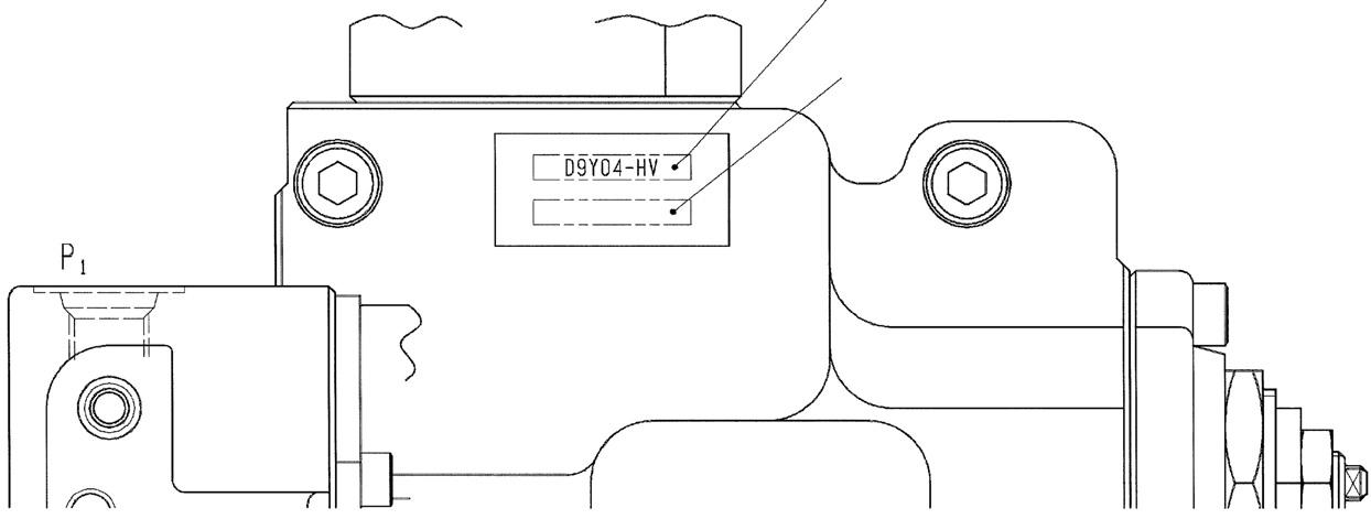
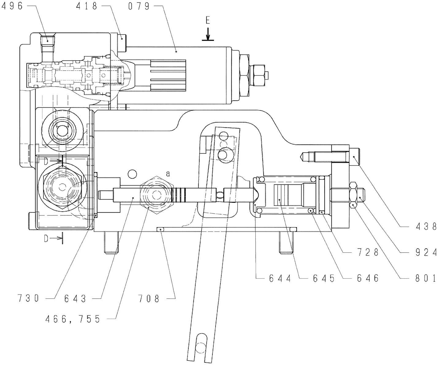
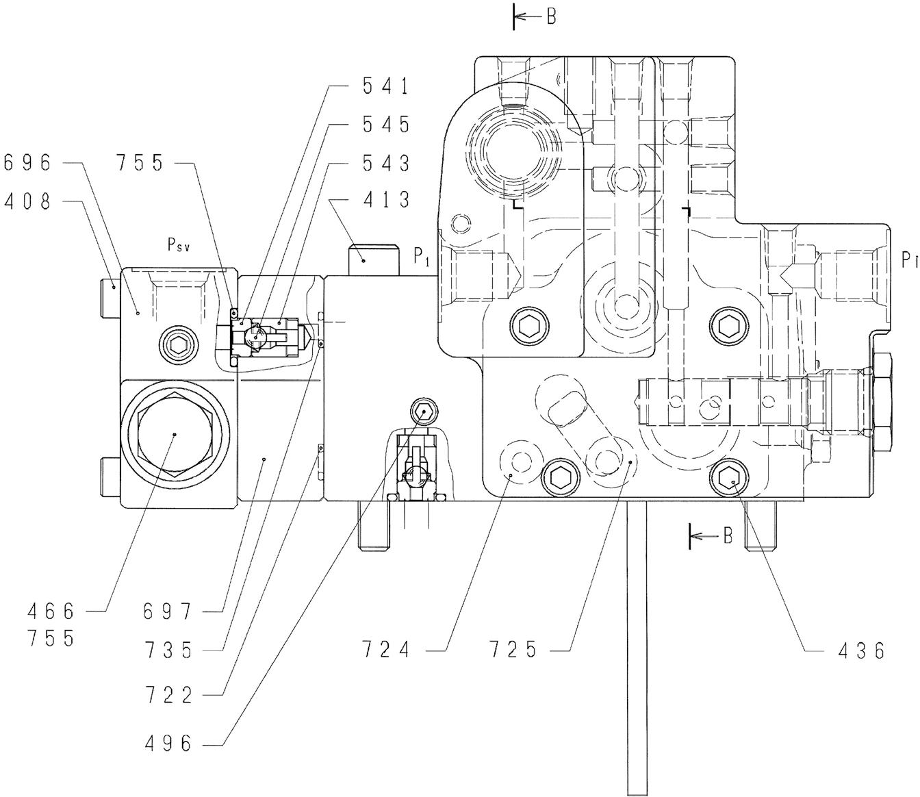
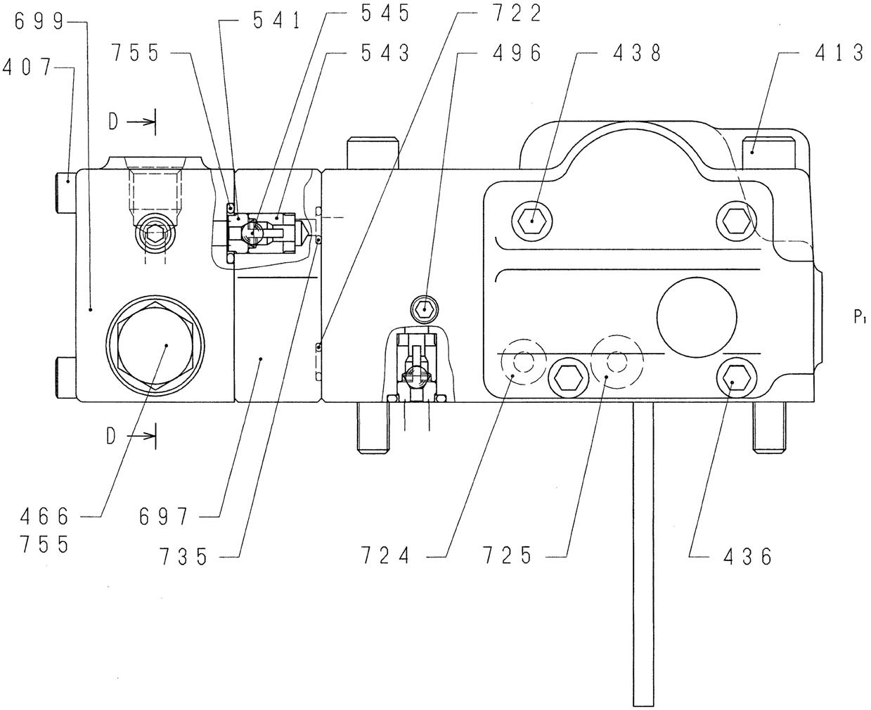
2.Disassembly preparations [1] These regulators comprise small precision parts, so assembly and disassembly operations are somewhat complex. [2] The pressure-flow settings of the front side regulator and the rear side regulator differ, so mark the regulators when disassembling to differentiate between the drive side and the driven side. [3] When disassembling the regulators, read this disassembly procedure thoroughly before following the sequence below. The numbers in parentheses after the part names are the codes indicated in "Diagram 1. Frontside regulator assembly cross-section diagram (KR3G-9Y04-HV)" "Diagram 2. Rear-side regulator assembly cross-section diagram (KR3G-9X04-HV)". 3.Disassembly procedures [1] Select a location for disassembly. •Select a clean location. •Place a rubber plate or cloth on the work platform so as not to damage the parts. [2] Use cleaning oil to remove any debris or rust from the surfaces of the regulators. [3] Remove the hexagon socket head bolt (438), and remove the cover (C) (629). •The cover (C) (629) is assembled with an adjusting screw (C) (628), adjusting ring (C) (627), lock nut (630), hexagon nuts (801) (802), and hexagon socket head locking screw (924). Do not loosen these screws and nuts. Doing so changes the adjusted pressure-flow setting. [4] After removing the cover (C) (629) subassembly, remove the outer spring (625), inner spring (626), and spring seating (C) (624) from the compensation section, and pull out the adjusting ring (Q) (645), pilot spring (646), and spring seating (644) from the pilot section. •The adjusting ring (Q) can be easily removed by pulling it out with an M4 bolt.
[5] Remove the hexagon socket head bolt (436), and remove the pilot cover (641).
After removing the pilot cover, remove the pin (898) and the Pf sleeve (631) from the compensation section and the set spring (655) from the pressure adjustment section. [6] Remove the stop ring (814), and remove the spring seating (653), return spring (654), and sleeve (651). •The sleeve is assembled with the retaining ring (836). •When removing the stop ring, the return spring flies out, so be careful not to lose this part. [7] Remove the retaining ring (836), and remove the fulcrum plug (614) and adjusting plug (615). •The fulcrum plug and adjusting plug can be easily removed by pulling them out with an M6 bolt.
[8] Remove the lever 2 (613). Do not pull out the pin (875). •This can be easily removed by using a pair of tweezers.
[9] Pull out the pin (874), and remove the feedback lever (611). •Use a fine steel rod to push out the pin (874) (pin diameter φ4) from above without touching the lever (1) (612).
[10]Remove the lever (1) (612). Do not pull out the pin (875). [11]Pull out the pilot piston (643) and spool (652). [12]Pull out the piston case (622), compensation piston (621), and compensation rod (623). •The piston case can be removed by pushing out the compensation rod from the opposite side of the piston case. [13]Remove the hexagon socket head bolt (418), and remove the electromagnetic proportional pressure reducing valve (079) from the pilot cover (641). This completes the disassembly of the regulator main unit. •This operation is only for the front-side regulator (KR3G-9Y04-HV). •Be careful not to damage the connector section of the electromagnetic proportional pressure reducing valve. (Caution) The component parts are small, so be very careful not to lose them.
4.Assembly procedures
The assembly procedure is the reverse of the disassembly procedure. However, follow the precautions below. (1) Be sure to repair any parts damaged during disassembly, and prepare replacement parts in advance. (2) Any foreign matter entering the equipment can create a malfunction. Therefore, after thoroughly cleaning the equipment with cleaning oil, air blow the equipment, and perform assembly in a clean location. (3) Be sure to apply clean hydraulic oil to sliding sections before assembly. (4) As a rule, replace all O-rings and other seal parts with new parts. (5) Use a torque wrench to tighten all installation bolts and plugs to the torque specified in "Maintenance Standards". [1] Select a location for assembly. •Select a clean location. •Place a rubber plate or cloth on the work platform so as not to damage the parts. [2] Install the compensation rod (623) into the compensation hole on the casing (601). [3] Insert the pin (875) press fit in the lever (1) (612) into the groove on the compensation rod (623), and install the lever (1) on the pin press fit in the casing (601). [4] Install the spool (652) and sleeve (651) in the casing spool hole. •Check that the spool and sleeve slide smoothly in the casing without catching. •Be careful to assemble the spool in the correct direction. [5] Install the feedback lever (611), and insert the pin (874) in alignment with the pin hole on the feedback lever. •Assembly is easier if the pin is inserted into the feedback lever in advance. •Be careful to assemble the feedback lever in the correct direction. [6] Install the pilot piston (643) into the pilot hole on the casing (601). •Check that the pilot piston (643) slides smoothly without catching. [7] Insert the pin (875) press fit in the lever (2) (613) into the groove on the pilot piston (643), and assemble the lever (2).
[8] Assemble the fulcrum plug and install the retaining ring (836) so that the pin (875) press fit in the fulcrum plug (614) is inserted into the pin hole on the lever (2) (613).
[9] Insert the adjusting plug (615), and install the locking ring (858). •Be careful to insert the fulcrum plug (614) and adjusting plug (615) into the correct holes. •At this time, check that the backlash from the movement of the feedback lever (611) is not too great and that the feedback lever (611) does not catch on anything.
[10]Install the return spring (654) and spring seating (653) into the spool holes, and install the stop ring (814).
[11]Install the set spring (655) into the spool hole, and install the compensation piston (621), piston case (622), Pf sleeve (631), and piston case (622) into the compensation holes. •Check that the Pf sleeve and pin move smoothly.
[12]Install the electromagnetic proportional pressure reducing valve (079) in the pilot cover (641), and tighten the hexagon socket head bolt (418).
Tightening torque: 6.9 N•m •This operation is only for the front-side regulator (KR3G-9Y04-HV). •Be careful not to damage the connector section of the electromagnetic proportional pressure reducing valve.
[13]Install the pilot cover (641), and tighten the hexagon socket head bolt (436).
Tightening torque: 12 N•m [14]Install the spring seating (Q) (644), pilot spring (646), and adjusting ring (Q) (645) into the pilot holes, and install the spring seating (Q) (624), inner spring (626), and outer spring (625) into the compensation holes. •Be careful to install the spring seating (Q) in the correct direction. [15]Install the cover (C) (629) set with the adjusting screw (C) (628), adjusting ring (C) (627), lock nut (630) ,hexagon nuts (801) (802), hexagon socket head locking screw (924), and tighten the hexagon socket head bolt (438).
Tightening torque: 12 N•m
This completes the assembly of the regulator main unit.


Code Part name Q'ty Component part No. (q'ty) or type 041 Check valve 1 subassembly 1 set KDRDE5K-31/30C50-102 050 Shuttle valve subassembly 2 set 541 (1PC), 543 (1PC), 545 (1PC) 079 Electromagnetic proportional pressure reducing valve 1 set 545 (1PC), 546 (1PC), 547 (1PC)
Part No. Part name Q'ty - Regulator subassembly 1 408 Hexagon socket head bolt 4 412 Hexagon socket head bolt 2 413 Hexagon socket head bolt 2 418 Hexagon socket head bolt 6 436 Hexagon socket head bolt 4 438 Hexagon socket head bolt 4 466 VP plug 2 467 VP plug 1 496 Mounted valve 12 541 Seat 2 543 Stopper 1 2 545 Steel ball 3 546 Seat 1 1 547 Seat 2 1 601 Casing 1 611 Feedback lever 1 612 Lever (1) 1 613 Lever (2) 1 614 Fulcrum plug 1 615 Adjusting plug 1 621 Compensation piston 1 622 Piston case 1 623 Compensation rod 1 624 Spring seating (C) 1 625 Outer spring 1 626 Inner spring 1 627 Adjusting ring (C) 1 628 Adjusting screw (C) 1 629 Cover (C) 1 630 Lock nut 1 631 Pf sleeve 1 641 Pilot cover 1 643 Pilot piston 1 644 Spring seating (Q) 1 Part No. Part name Q'ty 645 Adjusting ring (Q) 1
646 Pilot spring 651 Sleeve 1 1
652 Spool 653 Spring seating 654 Return spring 655 Set spring 696 Port cover 1 1 1 1 1
697 Check valve plate 698 Cover 1 1
708 O-ring 722 O-ring 724 O-ring 725 O-ring 727 O-ring 728 O-ring 730 O-ring 732 O-ring 733 O-ring 734 O-ring 735 O-ring 753 O-ring 755 O-ring 756 O-ring 763 O-ring 801 Hexagon nut 802 Hexagon nut 814 Stop ring 836 Retaining ring 874 Pin 1 3 8 1 1 1 1 1 1 1 1 1 12 1 1 1 1 1 1 1
875 Pin 2
876 Pin 2
887 Pin 897 Pin 1 1


Code Part name Q'ty Component part No. (q'ty) or type 041 Check valve 1 subassembly 2 set 541 (1PC), 543 (1PC), 545 (1PC) 079 Electromagnetic proportional pressure reducing valve 1 set KDRDE5KR-20/40C13-203A
Part No. Part name
Q'ty - Regulator subassembly 1 407 Hexagon socket head bolt 4 412 Hexagon socket head bolt 2 413 Hexagon socket head bolt 2 418 Hexagon socket head bolt 4 436 Hexagon socket head bolt 2 438 Hexagon socket head bolt 6 466 VP plug 1 496 Mounted valve 7 541 Seat 2 543 Stopper 1 2 545 Steel ball 2 601 Casing 1 611 Feedback lever 1 612 Lever (1) 1 613 Lever (2) 1 614 Fulcrum plug 1 615 Adjusting plug 1 621 Compensation piston 1 622 Piston case 1 623 Compensation rod 1 624 Spring seating (C) 1 625 Outer spring 1 626 Inner spring 1 627 Adjusting ring (C) 1 628 Adjusting screw (C) 1 629 Cover (C) 1 630 Lock nut 1 631 Pf sleeve 1 641 Pilot cover 1 643 Pilot piston 1 644 Snap ring seating (Q) 1 645 Adjusting ring (Q) 1 646 Pilot spring 1 Part No. Part name 651 Sleeve 652 Spool 653 Spring seating 654 Return spring 655 Set spring 697 Check valve plate 698 Cover 699 Valve casing 708 O-ring 722 O-ring 724 O-ring 725 O-ring 728 O-ring 730 O-ring 732 O-ring 733 O-ring 734 O-ring 735 O-ring 753 O-ring 755 O-ring 756 O-ring 763 O-ring 801 Hexagon nut 802 Hexagon nut 814 Stop ring 836 Retaining ring 874 Pin 875 Pin 876 Pin 887 Pin 897 Pin
Q'ty 1 1 1 1 1 1 1 1 1 3 8 1 1 1 1 1 1 1 1 11 1 1 1 1 1 1 1 2 2 1 1 898 Pin 1 924 Hexagon socket head locking screw 1
