
17 minute read
Assembly and Disassembly of Swing Motor


Caution 1. Read and understand the contents of this maintenance manual before performing disassembly, reassembly, inspection, repair, or other such work of this product. 2. Handle this product according to the separate "Usage Precautions". 3. When removing this product from the equipment it is mounted on, stop that equipment system and wait for the surface temperature of this product to fall to about 40 ℃ or below before removing it. Working on this product while it is still hot can cause burns. Additionally, always bleed out the pressure before removing any line from this product. Removing a pressurized line can result in oil spraying out and causing injury or oil leak. 4. Use the specialty tools and measurement instruments for disassembly, reassembly, inspection, and repair, etc. of this product. Using an inappropriate tool may result in injury or product damage. 5. Be careful of parts falling when performing disassembly, reassembly, inspection or repair, etc. of this product. This may result in injury or parts damage. 6. Do not directly touch with bare hands the machined edges or threaded sections of parts during disassembly, reassembly, inspection, or repair etc. of this product. This may result in injury. 7. Check performance after reassembly. Do not resume use unless performance is fully recovered. Using this product at a sub-par performance level may result in product damage. 8. The cautions (mark !) listed in this maintenance manual do not cover all possible dangers.
Always think of safety first during disassembly, inspection, reassembly, repair, or other such work.
1.Causes of trouble and solutions [1] General cautions This list consists of actions to be taken when an abnormality is sensed during use of the hydraulic motor. General cautions are listed below. 1) Think before attempting to fix a problem. Determine the nature of the abnormality before beginning work and think whether this same kind of problem has occurred before. Also, reconfirm whether the motor is the source of the problem. 2) Be careful about dust and dirt. The cause of wear is very often dust and dirt. So be careful that dust and dirt do not get into parts during disassembly. 3) Parts handling Parts are manufactured with a high degree of precision, so be careful not to scratch them during handling. 4) Do not damage O-rings or gasket surfaces while performing work. Also, it is recommended that O-rings are replaced for new ones during disassembly. [2] Investigating abnormalities in the motor main unit It is very difficult to search for the source of troubles in the hydraulic circuits. Inspect the following items and thoroughly investigate whether the motor is the source of troubles. 1) Inspecting oil within the casing Remove the drain plug and inspect the hydraulic oil within the casing. If a large amount of metal particles come out at the same time as oil, it is very likely that there is damage with parts within the motor. 2) Existence of abnormal noise Check whether abnormal noise is coming from the motor main unit. 3) Measure pressure for each part. Do not perform disassembly inspection carelessly. Measure pressure for each part and look for abnormalities in each area.
[3] Trouble conditions and countermeasures 1) Hydraulic motor does not rotate.
2) Rotation direction is reversed.
3) Motor speed is not reaching the set value.
4) Hydraulic motor does not rotate.
Symptom Pressure does not rise. Cause
1. Incorrect setting of the circuit safety valve 2. Operation problems with relief valve ・ Plunger sticking ・ Clogged plunger orifice 3. Plunger seating problem
Pressure rises. 1. Overload 2. Seizing of driving part
3. No release pressure acting on the brake 4. Piston sticking to the brake 5. Spool for brake release sticking 6. Friction plate seizing Solution
1. Reset safety valve correctly.
2. Disassemble and inspect. ・ Repair or replace sticking section. ・ Disassemble and clean. 3. Check seating sections and replace scratched part. 1. Eliminate load. 2. Inspect and repair piston/shoe, cylinder/valve plate, etc. 3. Inspect and repair circuit.
4. Disassemble and inspect. 5. Disassemble and inspect. 6. Disassemble and inspect. Replace seizing part.
Symptom Reversed rotation direction Cause
1.Motor rotation direction reversed.
2. Input and output for line reversed. Solution
1. Check the rotation direction and assemble correctly. 2. Correct line configurations.
Symptom Rotation speed does not reach the setting value. Cause
1.Insufficient oil flow amount
2. High temperature and severe leak of oil 3. Wear or damage on each sliding section Solution
1. Check the pump discharge volume and the circuit up to the motor. 2. Lower the temperature of the oil.
3. Replace part.
Symptom Insufficient braking torque Cause
1. Wear on the friction plate
2. Brake piston sticking 3. Brake release pressure cannot be released. 4. Spool for brake release sticking 5. Damaged friction plate spline Solution
1. Disassemble and inspect. Replace parts worn beyond the limit. 2. Disassemble and inspect. 3. Inspect and repair circuit.
4. Disassemble and inspect. 5. Disassemble and inspect. Replace damaged part.
5) Severe hydraulic motor slipping
Investigate the amount of oil drained from the hydraulic motor.
Motor operation is normal if the amount is 500 cc/min or less.
6) Oil leak 1) Oil leak from oil seal
2) Oil leak from matching surface
Symptom Slipping is severe when an external driving torque acts on the hydraulic motor. Cause
1. Operation problems with relief valve ・ Plunger sticking ・ Clogged plunger orifice 2. Plunger seating problem Solution
1. Disassemble and inspect. ・ Repair or replace sticking section. ・ Disassemble and clean. 2. Check seating section and replace scratched part.
Symptom Cause
Oil leak from oil seal 1. Debris lodged in lip causing scratching. 2. Shaft scratched or worn
3. Pressure within the casing becoming abnormally high caused oil seal lip to turn up. 4. Shaft rusted. Solution
1. Replace oil seal.
2. Stagger the position of the lip and shaft or replace it. 3. Repair any clogged drain line.
4. Disassemble and repair.
Symptom Oil leak from matching surface Cause
1. O-ring has not been inserted.
2. Scratched O-ring 3. Scratched seal surface 4. Loosened or damaged bolt Solution
1. Insert O-ring and assemble correctly. 2. Replace part. 3. Disassemble and repair. 4.Tighten to the specified torque or replace.
2.Maintenance procedures [1] Replacement standards for worn parts If wear on any part exceeds the standard values below, replace or readjust that part. However, parts should be replaced regardless of these standards if they appear to be extremely damaged based on appearance.
[2] Sliding surface repair standards
If the roughness of the sliding surface of any part exceeds the standard values below, repair or replace that part.
Note:1. Using lapping, make the degree of surface roughness of each sliding surface equal to or lower than the standard value. 2. If the holder plate and spherical surface sliding section are rough, these should be replaced as a set.
Table 1 Part replacement standards
Item
Clearance between piston and cylinder bore (D-d) Standard dimensions (mm)
Recommended replacement value (mm) Solution
0.032 0.062 Replace the piston or cylinder.
Piston and shoe caulking section backlash (δ) 0 0.3 Replace the piston and shoe assembly.
Shoe thickness (t) 6 5.8 Replace the piston and shoe assembly. Assembled height of holder plate and spherical bushing (H-h) 7 6.5 Replace holder plate and spherical bushing as a set. Friction plate thickness 4.0 3.6 Replace the part.

Table 2 Sliding surface repair standards Part name Standard surface roughness Surface roughness requiring repair Shoe 0.8 - Z (Ra = 0.2) (lapping) 3 - Z (Ra = 0.8) Shoe plate 0.4 - Z (Ra = 0.0) (lapping) 3 - Z (Ra = 0.8) Cylinder 1.6 - Z (Ra = 0.4) (lapping) 12.5 - Z (Ra = 3.2) Valve plate 0.8 - Z (Ra = 0.2) (lapping) 6.3 - Z (Ra = 1.6)
3.Assembly and disassembly [1] Bolt tightening torque Tightening torque values for bolts used in the motor are indicated in Table 3. When assembling, securely tighten bolts to the values in Table 3.
For other bolts and plugs, see the assembly cross-section diagram. [2] Tools for assembly and disassembly
The necessary tools for assembly and disassembly are indicated in Tables 4 and 5. The bolts and plugs used vary for each type, so prepare tools based on examination beforehand.
Screw size Name Table 3
Tightening torque N•m Applicable part code
M33 Relief valve 177 51 M22 Reverse prevention valve 69 400 M22 Hexagon socket head bolt 627 401 M8 Hexagon socket head bolt 29 171 G1/4 Plug 36 464 M36 RO plug 539 469 Rc1/2 Mounted valve 65 992 Rc3/4 Mounted valve 98 994
Table 4 Wrenches
Name Size Bolt width Applicable code and part
Hexagon socket head bolt M8 6 Reverse prevention valve Tool
Hexagon wrench
Hexagon socket head bolt M22 17 Hexagon wrench
Plug M36 17 RO plug Hexagon wrench Plug G1/4 19 VP plug Hexagon wrench, socket wrench Reverse prevention valve M22 24 Hexagon wrench, socket wrench Relief valve M33 41 Hexagon wrench, socket wrench
Table 5 Other
Dimensions
Pliers
For stop ring For φ50 shaft For locking ring For φ110 hole, φ62 hole Screwdriver Medium-sized flathead × 2 Steel rod About size 10 × 8 × 200 × 1
Hammer Plastic hammer Metal hammer 1 each
Torque wrench Torque adjustment range ・ For 9.8 - 44 N•m ・ For 39 - 177 N•m ・ For 118 - 627 N•m
Slide hammer bearing puller Brake piston removal jig See the diagram below.
Brake piston removal jig
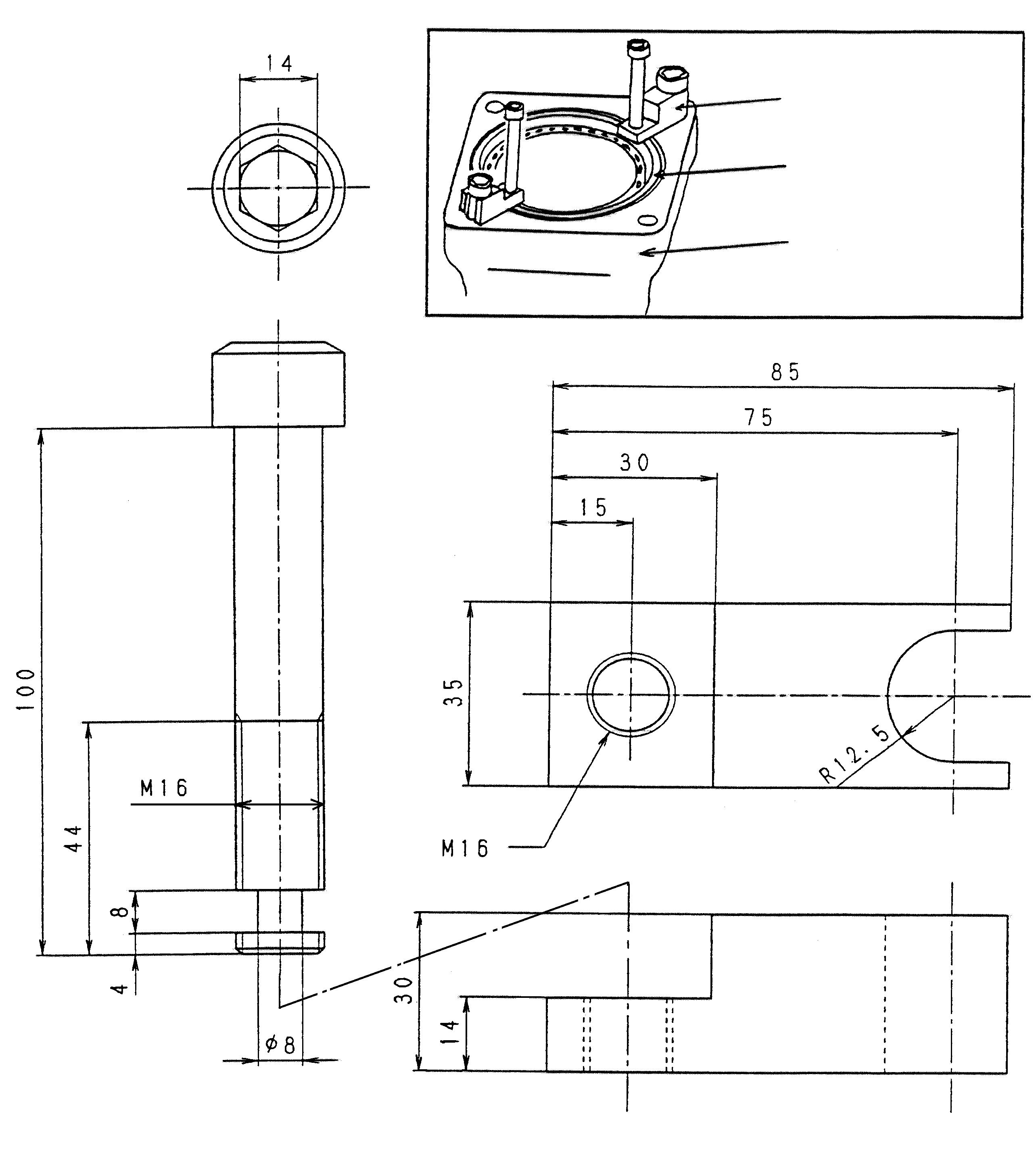
(Units: mm)
[3] Disassembly procedure
When disassembling the motor, disassemble using the sequence indicated below. The numbers in parentheses after the part names are the codes used in the structure diagram. a.Wrap the wire rope around the outer circumference of the motor, lift the motor with a liftcrane, and clean with white kerosene. After cleaning, dry the motor using compressed air. •To prevent foreign matter from entering the motor, mask each port with tape, etc. before cleaning off adhered dirt and dust. b.From the drain plug, drain the oil inside the casing (301). c.Point the shaft end of the drive shaft (101) downwards and secure the motor on a surface which makes disassembly easy. At this time, place reference marks on the sections of the casing (301) and valve casing (303) that match with each other. •Select a clean location for disassembly. Place a rubber plate or cloth on the platform so as not to damage the parts. d. Loosen the relief valves (051) and the reverse prevention subassembly, and remove them from the valve casing (303). •O-rings will be damaged when the relief valves are loosened, so be sure to replace the O-rings.
e.Loosen the reverse prevention valve and remove it from the valve casing (303). f. Remove the ROMH plugs (469) from the valve casing (303) and take out the springs (355) and plungers (351). •Be careful not to scratch the plunger seating sections.
g. Loosen the hexagon socket head bolts (401) and remove the valve casing (303) from the casing. (The valve casing will rise up from the casing when the bolts are removed due to the force of the brake springs (712).)
Additionally, remove the valve plate (131) from the valve casing. •Do this carefully so as not to let the valve plate fall from the valve casing. (The valve plate may be attached to the cylinder side.)
When prying open the matching surface with a screwdriver, etc., be careful not to scratch the surface. h.Take out the brake springs (712) from the brake piston (702).
i. Use a jig and remove the brake piston (702) from the casing (301). •Apply the tips of the jig to the sides of the brake piston. Pull the brake piston out straight up.
j. Move the motor on its side so that it is horizontal with the ground and remove the cylinder (111) from the drive shaft (101).
Additionally, remove the pistons (121), holder plate (123), spherical bushing (113), spacer
F (117), and shoe plate (124). •Be careful not to scratch the sliding surfaces of the cylinder, shoe, etc.
If the shoe plate cannot be removed, proceed to 11) and remove.
k.Take out the friction plates (742) and separator plates (743) from the casing (301). l. Use pliers to remove the locking ring, and then remove the front cover from the casing (301). •Be careful not to scratch the sliding surfaces of the oil seal when removing the front cover.
m.Tap the end surface of the valve casing side of the drive shaft (101) with a plastic hammer, and remove from the casing. •The spline will damage the oil seal (491) when the drive shaft is removed, so wrap the spline section of the drive shaft with vinyl tape, etc. (*1). n.Remove the shoe plate from the cylinder roller bearing (443) (housing section side) of the casing (301) by tapping with a copper rod.
o.Perform the following as necessary. 1.Remove the stop ring spacer from the drive shaft (101), and use a press to remove the inner race of the cylinder roller bearing (443). •It is acceptable to strike the inner race of the cylinder roller bearing using a steel rod, but be careful to strike the inner race evenly and to not damage the bearing. Do not reuse removed bearing. 2.Use a jig to remove the oil seal (491) from the front cover (304). 3.Use the slide hammer bearing puller (*2) to remove the cylinder roller bearing (444) from the valve casing (303). •Do not reuse removed bearing.
This completes the disassembly. Thoroughly inspect each section for abnormalities.
[4] Assembly procedure
The assembly procedure is the reverse of the disassembly procedure. However, follow the precautions below. •Be sure to repair any parts damaged during disassembly, and prepare replacement parts in advance. •Thoroughly clean all parts with cleaning fluid and dry with compressed air. •Be sure to apply clean hydraulic oil on sliding parts and bearings before assembling. •As a rule, replace all O-rings, oil seals, and other seal parts with new parts. •Use a torque wrench to tighten all installation bolts and plugs to the torque values specified in
Table 3.
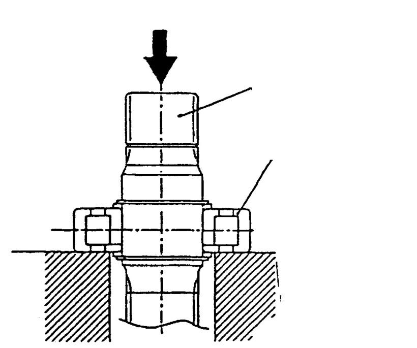
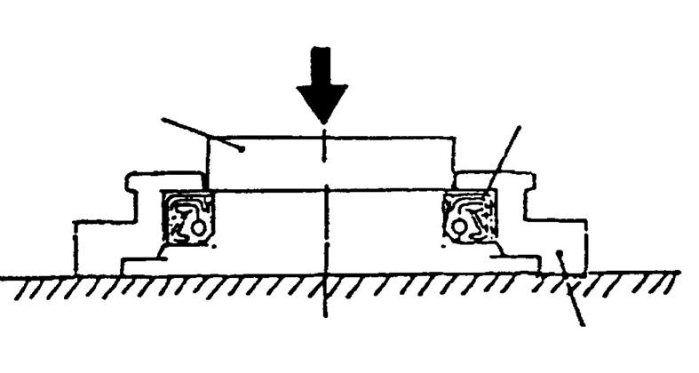
The assembly procedure is indicated below. a. Place the casing (301) on an appropriate platform with the valve casing (303) side facing up. b.(This section is only necessary when the cylinder roller bearing (443) is removed.) Shrink fit the inner race of the cylinder roller bearing to the drive shaft (101). Next, insert a spacer and mount the stop ring. Lastly, insert the flange of the cylinder roller bearing into the drive shaft (101) and mount the stop ring. •Be careful with the direction of the flange of the cylinder roller bearing. c.Place the output shaft side of the drive shaft (101) with the inserted cylinder roller bearing (443) face up and insert into the casing (301), and then install by tapping the outer race of the cylinder roller bearing (443) with a hammer and copper rod. •Evenly strike the outer circumference of the outer race completely in until it stops at the stepped section of the casing. d. Use a jig to insert the oil seal (491) into the front cover (304). •Be careful with the direction of the oil seal. (See the diagram below.) Apply a thin layer of grease to the oil seal lip section. Evenly strike the oil seal and be careful not to scratch the outer circumference.

e.Mount the O-ring on the casing (301).
f. Mount the drive shaft (101) in the casing (301). •Carefully insert it so as not to scratch the lip section of the oil seal (491).
Wrapping vinyl tape, etc. around the shaft spline section to protect it is recommended. g.Mount the locking ring on the casing (301) with pliers.
h.Lay the casing (301) horizontal and insert the shoe plate (124). •Install with the larger chamfered side of the shoe plate on the casing side.
Apply a thin layer of grease to the matching surface to prevent it from falling out. i. Insert the push rod into the cylinder. Additionally, place the spherical bushing with the assembled spacer on the cylinder. •Be careful not to scratch the sliding surfaces of the cylinder. (Insert 2 push rods at a time in 1 hole.)
j. Set the piston subassembly (10) in the holder plate (123).
k.Install the piston subassembly (10) set in the holder plate (123) into the cylinder (111).
Then align the cylinder with the spline of the drive shaft (101) and insert it.
l. Set the casing (301) down with the front cover side facing downwards and alternately install separator plates (743) and friction plates (742) in that order to the casing.
Install the 3 separator plates and 2 friction plates.
m.Mount the O-rings (706) and (707) on the casing (301). •If a thin layer of grease is applied to the Orings, they will not break easily when inserting brake piston.
n.Install the brake piston (702) into the casing (301).
o.Install the brake springs (712) into the brake piston (702).
p.(This section is only necessary when the cylinder roller bearing (444) is removed.)
Install the outer race of the cylinder roller bearing into the valve casing (303) with a steel rod by lightly striking the rod with a hammer.
•Evenly strike the outer circumference of the outer race completely in until it stops at the stepped section of the valve casing.
q.Install the valve plate (131) into the valve casing (303) and also mount the O-ring (472). •Apply a thin layer of grease to the valve plate matching surface to prevent falling. (*1)
r. Install the valve casing (303) on the casing (301) and tighten with the hexagon socket head bolts (401).
Tightening torque: 627 N•m •Be careful with the installation direction of the valve casing.
Make sure that the valve plate (131) does not come off.
Make sure that the brake springs (712) do not fall over.
Tighten the hexagon socket head bolts equally.
s.Insert the plungers (351) and springs (355) into the valve casing (303) and tighten the
ROMH plugs (469) with the O-rings (488) mounted on them to the valve casing.
Tightening torque: 539 N•m •Check that the plungers move smoothly.
t. Mount the backup ring and O-ring on the relief valve (051) and tighten them to the valve casing.
Tightening torque: 177 N•m u.Mount the reverse prevention subassembly to the valve casing (303). •Do not forget the O-rings. v. Mount the O-ring on the plug and tighten it to the valve casing (303). Additionally, mount the O-ring on the plug and tighten it to the casing (301).
This completes the assembly.
Internal Structure Diagram

Tightening torque Part No. Screw size Tightening torque N•m 051 M33 × 1.5 177 151 G1/4 36 171 M8 29 400 M22 × 1.5 69 401 M22 627 464 G1/4 36 469 M36 × 1.5 539 982 G1/4 0.9 984 G1/2 2.7 985 G1 5.6 992 Rc1/2 65 994 Rc3/4 98
Part No. Part name Q'ty 052 Reverse prevention valve subassembly 1 set 100 Casing 2 151 Plug 2 161 O-ring 2 162 O-ring 2 163 O-ring 2 171 Hexagon socket head bolt 4 400 Reverse prevention valve 2 (400-1) O-ring 2 (400-2) Backup ring 2 Part No. Part name Q'ty 011 Piston subassembly 1 set 121 Piston 9 122 Shoe 9 020 Valve casing subassembly 1 set 303 Valve casing 1 451 Pin 2 101 Drive shaft 1 106 Spacer 3 111 Cylinder 1 113 Spherical bushing 1 114 Cylinder spring 1 116 Push rod 12 117 Spacer F 1 118 Spacer R 1 123 Holder plate 1 124 Shoe plate 1 131 Valve plate 1 301 Casing 1 304 Front cover 1 351 Plunger 2 355 Spring 2 390 Nameplate 1 391 Striking pin 2 401 Hexagon socket head bolt 4 432 Stop ring 2 433 Retaining ring 1 437 Locking ring 1 438 Locking ring 1 443 Cylinder roller bearing 1 444 Needle pin roller bearing 1 464 ROH plug 1 469 ROMH plug 2 471 O-ring 1 472 O-ring 1 485 O-ring 1 488 O-ring 2 491 Oil seal 1 702 Brake piston 1 706 O-ring 1 707 O-ring 1 712 Brake spring 18 742 Friction plate 3 743 Separator plate 4 982 Masking plug 1 984 Masking plug 1 985 Masking plug 1 992 Mounted valve 1 994 Mounted valve 1 051 Relief valve 2 set 051-1 O-ring 2
