3 minute read
Removal and Installation of EGR Cooler and EGR Valve


k.Spring (26) attachment
Insert the springs (26) into the 12 spring mounting holes (26) on the brake piston (21).
Caution:
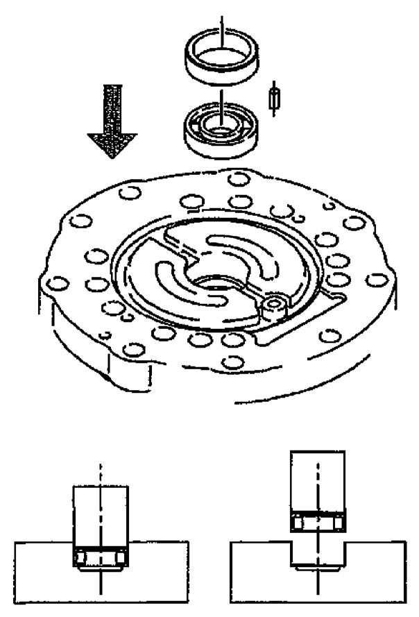
Some model motors may have a different number of springs (26). If there are not enough springs for the 12 spring mounting holes, have the empty holes facing each other diagonally as in the cross-section diagram. If empty holes are clustered on one side, the parking brake effectiveness may deteriorate. l. Valve plate (5) attachment
Place the base plate (2-1) on top of the work platform and press fit the roller bearing (14) in the center of the base plate (2-1) using the bearing press-fit jig.
At this time, remove the bearing inner race beforehand and install on the top tip of the motor shaft (3).
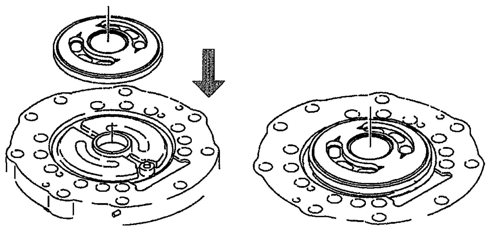
Check that the pin (16) and collar (15) are mounted to the base plate (2-1), then attach the valve plate (5) to the base plate (2-1).
Caution: •Place the spherical side of the valve plate (5) upwards to attach it. •Thoroughly apply grease (*2) to the matching surface between the base plate (2-1) and valve plate (25) to prevent the valve plate (5) from falling. •Be careful not to scratch the valve plate (5) spherical surface.
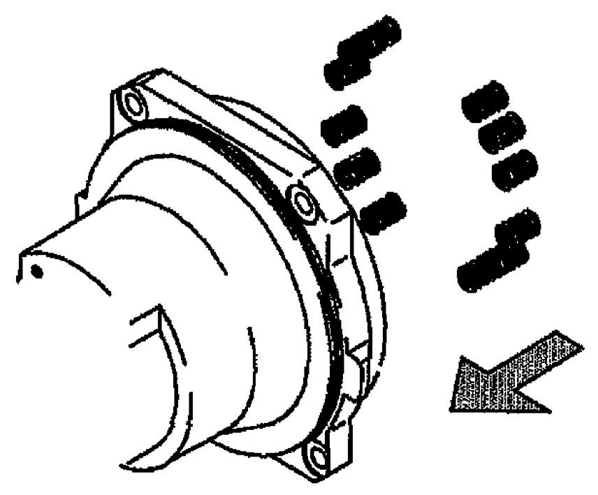
m.Base plate assembly (2) attachment
Attach the O-ring (29) and the 4 O-rings (30) to the top surface of the case (1).
Attach the 4 knock pins (27) to the base plate (2). Place the valve plate (5) mounting surface of the base plate assembly (2) downwards and tighten it to the case (1) with the 9 hexagon socket head bolts (33).
Caution: •Apply grease to the O-ring (29). •Do not apply grease to the O-rings (30). •Attach the knock pins (27) with their tapered sections up. Motors that have no parking brake function have 2 knock pins (27) for the case (1). •Apply hydraulic oil to the valve plate (5) surface and cylinder block (4) surface, then attach the base plate assembly (2). •When attaching the base plate assembly (2), be careful that the valve plate (5) does not fall because the valve plate (5) mounting surface is pointing down. •Check the mounting position of the Orings (30) on the case (1) and the position of the holes for the oil path on the base plate (2), then attach it. •Check that the positioning is such that the knock pins (27) and spring mounting hole (26) on the base plate assembly (2) side line up with the knock pin holes and brake piston spring (26) positions on the case (1) side, then attach. When tightening the hexagon socket head bolts (33), screw in all of the bolts around the circumference evenly.
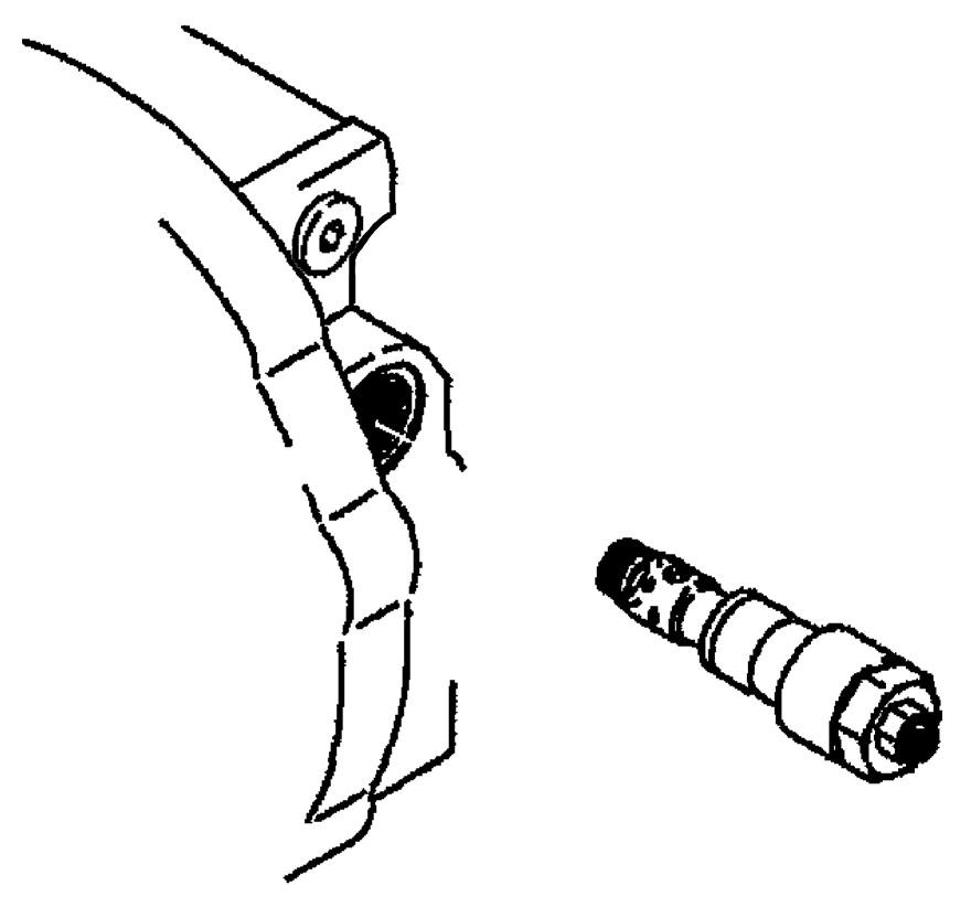
n.Valve assembly (2-9) attachment
Attach the spring (2-13) to the valve assembly (2-9), then attach the assembly to the base plate (2-1). After attaching the valve assembly (2-9), check that the O-ring (2-15) is mounted on the plug (2-14), then tighten the plug (2-14) to the base plate (2-1) to the specified torque.
Next, check that the O-rings (2-15) are mounted to the plug (2-17), attach the spring guide (2-16) and washer (2-18), then tighten the plug (2-17) to the base plate (2-1) to the specified torque.
Caution: •Attach the valve assembly (2-9) to the base plate (2-1) so that the base plate (2-1) line port side is on the side nearest to the installer and the valve assembly (2-9) spring (2-13) mounting side is on the right. Attaching in the opposite direction may cause problems such as switching errors. •Attach the valve assembly (2-9) after applying hydraulic oil to the outer circumference. •After attaching the valve assembly (29), check that it moves smoothly. o.Relief valve assembly (2-7) attachment
Check that the poppet (2-7-3) is mounted on the end of the relief valve assemblies (2-7), then attach the relief valve assemblies (2-7) to the base plate (2-1) and tighten to the specified torque.
Caution: •Replace the O-ring (2-7-12) with a new one before attaching the relief valve assemblies. •Check that the O-ring (2-7-12) and backup rings (2-7-16) are mounted on the poppet seat (2-7-1). •Apply grease to the O-ring (2-7-12) and backup rings (2-7-16) before attaching.