3 minute read
Removal and Installation of Turbo Charger


3.Install 9 piston assemblies (6), one in each of the 9 holes on the retainer plate (7).
Caution: When attaching, check that the outer circumference of the retainer plate (7) is tapered and with the tapered surface of the retainer plate down, insert the piston assemblies (6) from the side (up) opposite from the tapered surface.
4.Attach the piston assemblies (6) and retainer plate (7) to the cylinder block (4).
Caution: •Apply hydraulic oil to the 9 cylinder block (4) piston attachment holes before attaching the piston assemblies (6). •Apply hydraulic oil to the spherical surface of the retainer holder (8) before attaching it.

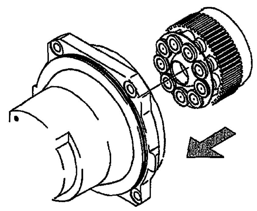
h.Cylinder block assembly attachment
Point the valve plate sliding surface side of the cylinder block assembly (cylinder block (4)) upwards, mesh the internal teeth splines of the retainer holder (8) and cylinder block (4) with the external teeth splines of the shaft (3), and install the cylinder block assembly inside the case (1).
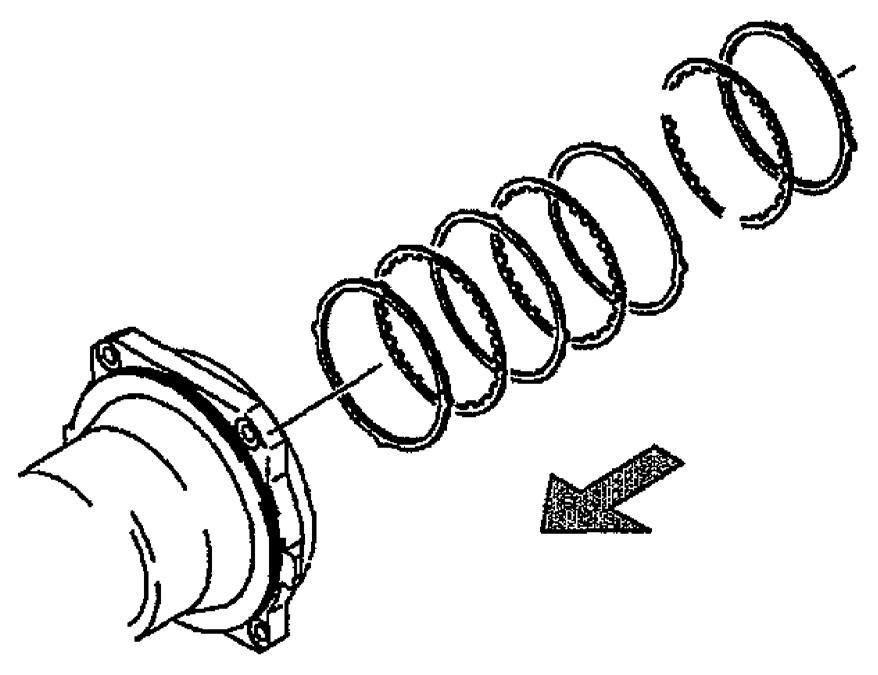
Caution: •When attaching, be careful that the piston assemblies (6), retainer plate (7) and retainer holder (8) do not come off from the cylinder block assembly. •Before attaching, apply hydraulic oil to the swash plate (9) surface and sliding surfaces of the piston assemblies (6). i. Disk plate (19) attachment
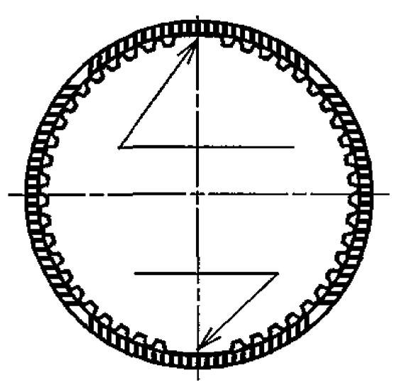
Align the arc section on the outer circumference of a friction plate (18) with the notch section (*1) of the case (1) and attach the friction plate (18) to the case (1). Mesh the internal teeth of a disk plate (19) with the external teeth of the cylinder block (4) and attach the disk plate to the case (1). Next, align the arc sections on the outer circumference of a friction plate (20) with the notch sections of the case (1) and attach the friction plate (20) to the case (1). In this way, attach the disk plates (19) and friction plates (20) alternating. After attaching the last disk plate (19), attach the friction plate (18) again.
Caution: •The disk plates (19) are wet type disks. Before attachment, immerse the friction material parts in hydraulic oil and have the friction materials thoroughly absorb the hydraulic oil. •Install all the disk plates (19) and friction plates (20) alternating so that they are sandwiched by 2 friction plates (18). •In some model motors, dummy friction plates (53) of thickness equivalent to 1 disk plate (19) and 1 friction plate (20) are installed for adjustment.
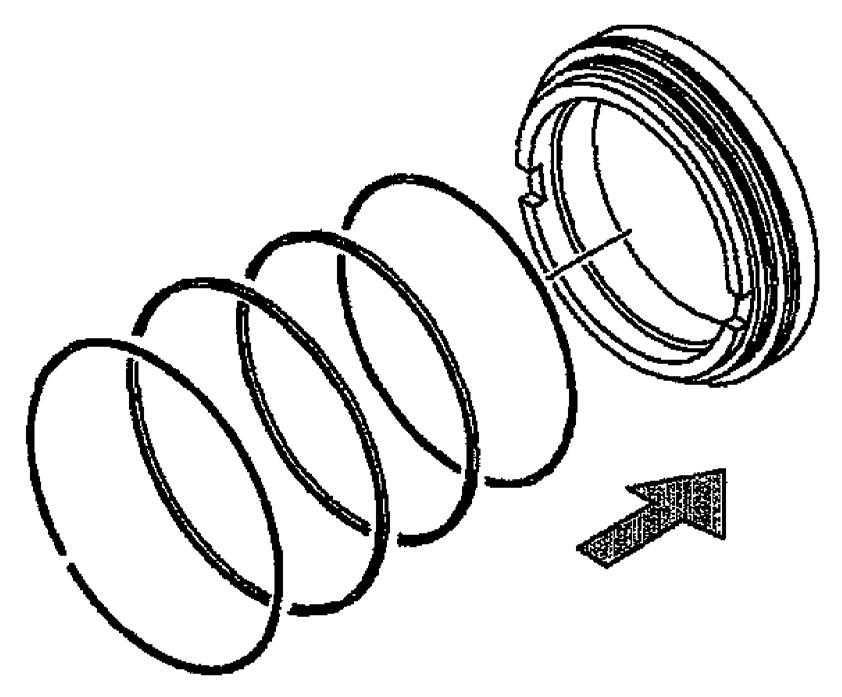
j. Brake piston (21) attachment
Attach the O-ring (22), backup ring (23),
O-ring (24), and backup ring (25) to the brake piston (21). Next, place the large bore side of the brake piston (21) upwards and attach it to the case (1).
Caution: •Thoroughly apply grease when attaching the O-ring (22), backup ring (23),
O-ring (24), and backup ring (25). •Be careful to mount the O-ring (22), backup ring (23), O-ring (24), and backup ring (25) in their correct positions. If they are mounted in the wrong positions, the parking brake may not work normally. •Use a positioning jig to align the case (1) base plate (2-1) knock pin hole and brake piston (21) knock pin hole, then attach the brake piston (21). •When attaching the brake piston (21), apply grease to the outer circumference of the brake piston and inner diameter section of the case (1). •Push and attach the brake piston (21) evenly all around so that it does not become slanted. If the brake piston is attached at a slant, this could cause operational problems or O-ring to break.