
8 minute read
Removal and Installation of Injector


Applicable part Inspection and measurement location
Spring (2-4) 1. Appearance dimensions
2. Appearance
Spring (2-13) 1. Appearance dimensions
2. Appearance
Spring (2-20)
Spring (12) 1. Appearance dimensions
2. Appearance
1. Appearance dimensions
2. Appearance
Spring (11) 1. Appearance dimensions
2. Appearance
Spring (26) 1. Appearance dimensions
2. Appearance
Each O-ring and oil seal Permissible limit value Repair, solution procedure
Free length 65 mm
There is deformation and scratching on the coil surface.
Free length, see the list at the end of this document
There is deformation and scratching on the coil surface. Replace the spring.
Replace the spring.
Free length 42 mm
There is deformation and scratching on the coil surface. Replace the spring.
Free length 49.7 mm
There is deformation and scratching on the coil surface. Replace the spring.
Free length 41.8 mm
There is deformation and scratching on the coil surface. Replace the spring.
Free length 40.3 mm
There is deformation and scratching on the coil surface.
During disassembly Replace the spring.
Replace each O-ring and oil seal.
(2) Reduction gear parts maintenance standards
Table 7. Usage limit criteria
As a rule, replace each part when its usage limit criterion below is reached.
No. Part name Usage limit criterion 01 Carrier A assembly 1. If there is extreme wear, peeling, or the like on spline teeth 08 Carrier B assembly 2. If there is extreme pitting, peeling, or the like on gear teeth 15 Carrier C assembly 3. If there are abnormalities in rotation of the planetary gear (abnormal noise, unsmooth rotation)
20 Sun gear A 21 Sun gear B 22 Sun gear C 23 Ring gear 25 Floating seal
26 Roller bearing 1. If there is extreme pitting, peeling, or the like on gear teeth
1. If there are scratches or the like that are causing oil leak on a sliding surface 1. If there are abnormalities in rotation (abnormal noise, unsmooth rotation)
5.Assembly of motor (1) Precautions before motor assembly Begin motor assembly only after thoroughly reading the precautions below. [1] When performing assembly, always wear protective devices such as a helmet, goggles and safety shoes. [2] Use the specified tools when performing assembly. [3] To prevent injuries during disassembly, prepare a waist-high, stable work platform to perform work on. [4] The motor comprises high-precision parts. For this reason, foreign matter adhering to parts can be damaging. Motor assembly should be done in an inside space without dust, and mud and dirt should be prevented from adhering to parts. [5] The motor comprises high-precision parts. For this reason, dents and scratching on part surfaces can be damaging. Be very careful when handling parts during assembly and do not create any dents or scratching. [6] Be sure to repair any damage discovered during disassembly and prepare replacement parts before beginning assembly. [7] Remove metal fragments and foreign matters from all parts and check that there are no burrs or dents on parts before beginning assembly. If there are burrs or dents, use a whetstone to remove them. [8] When performing assembly, apply clean hydraulic oil to each sliding and rotating sections before assembly. [9] Thoroughly degrease areas where Loctite and liquid packing is used and remove oil and water before assembly. [10]Replace all seal parts such as O-rings and backup rings with new parts. [11]Be careful not to damage O-rings and backup rings during assembly. When assembling Orings and backup rings, apply a small amount of grease for assembly. [12]Use petroleum jelly or grease to prevent parts from falling during assembly. [13]Tighten each type of bolts at the fastening sections to the tightening torque indicated in Table 5 in 3. (2). Tightening torque should be controlled with a torque wrench. [14]After assembly is complete, plug all ports leading into the motor to prevent dirt from entering.
(2) Assembly procedure
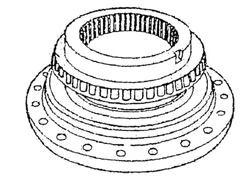
Perform assembly by observing the precautions listed in 5. (1) and following the procedure indicated below. [1] Assembly of reduction gear section See "Reduction gear structure diagram". a.Coat the inner surface of the motor case (24) and the O-ring of the floating seal (25) with grease and install the floating seal (25) in the motor case (24). Assemble in such a way that the floating seal (25) O-rings are not twisted. (Install the floating seal (25) in the drum case (30) side in the same manner.)
b.Install the motor side roller bearing (26) inner race on the motor case (24).
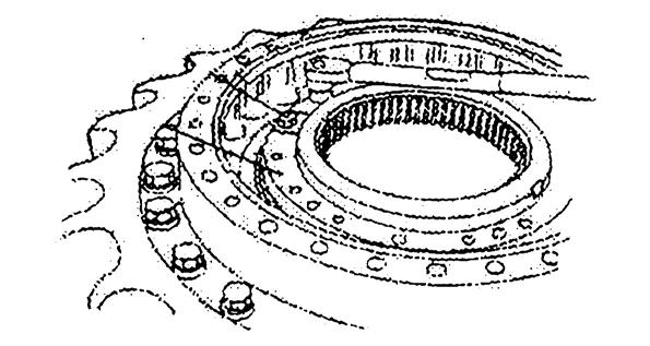
c.Install the roller bearing (26) outer races on both the drum case (30) motor side and reduction gear side. d.Next, install the roller bearing (26) inner race on the reduction gear side.
e.Coat the nut (27) threaded section and roller bearing (26) contact surface with grease, install in the motor case (24) and lightly tighten, then use a jig (*1) to tighten the nut (27) with a torque wrench.
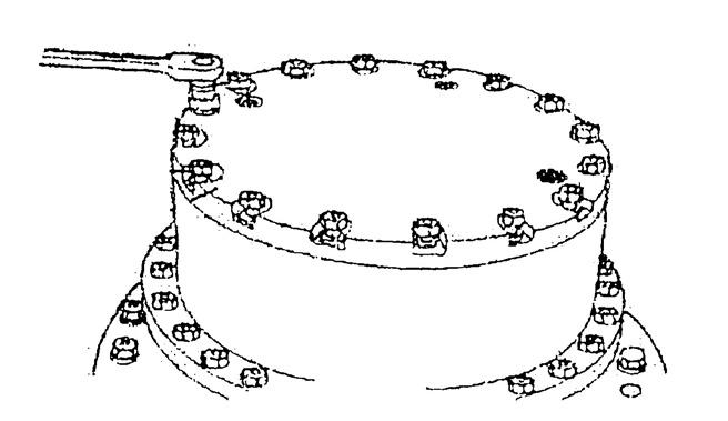
f. After tightening the nut (27), while rotating the drum case (30) in the counterclockwise direction and tapping the drum case (30) side surface with a plastic hammer to fit the parts in, tighten the nuts (27) 2-3 times. After this, tighten the nuts (27) again.
Tightening torque: 784.5 N•m
g.Install the lock plate (28) projection section at one of the 2 notch sections in the motor case (24). Align the tightening direction for the nut (27), apply Loctite #242 to the 2 bolts with washers (29), then tighten.
Tightening torque: 70.6 N•m


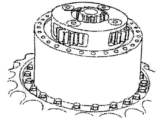
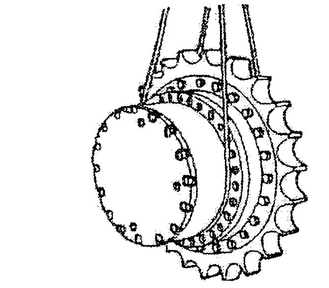
h.Install the eyebolt M10 (*3) on the 3rd stage carrier assembly (*2), lift up with the liftcrane, then install, meshing with the motor case (24) spline.
i. Install the eyebolt M10 (*4) on the ring gear (23), lift up with the liftcrane, then install in the drum case (30), meshing with 3rd stage carrier assembly planetary gear C (16).
At the same time, install the parallel pin (31) in the drum case (30) and ring gear (23).
j. Install the 3rd stage sun gear C (22) in the 3rd stage carrier assembly.
k.Install the eyebolt M10 (*5) on the 2nd stage carrier assembly (*6), lift up with the liftcrane, and install the eyebolt M10 (*5), meshing with the 3rd stage sun gear C (22), and then install sun bolt B (21) on the 2nd stage carrier assembly.
l. While meshing it with 2nd stage sun gear B (21), install the 1st stage carrier assembly (*7) and install 1st stage sun gear A (20) in the 1st stage carrier assembly.


m.Install the ball bearing (34) and thrust button (33) in the cover (32).
n.Degrease the installation surface of the drum case (30), apply ThreeBond #1215, install the cover (32), then tighten with the 20 hexagon socket head bolts (35).
Tightening torque: 178.4 N•m
o.Tighten the plug assembly (36) to the cover (32) to the specified torque.
Tightening torque: 70.9 N•m
p.Face the motor installation section up, fill the stipulated volume of lubricating oil (*8) from the installation section, then install the O-ring (40) on the motor.
q.Install the oil motor (37) and tighten with the 4 hexagon socket head bolts (38).
Tightening torque: 456 N•m


[2] Assembly of motor section
See "Travel motor breakdown diagram""Travel motor structural diagram" and "Travel motor part table". a.Oil seal (28) attachment Check that the old oil seal (28) is not mounted on the case (1). If it is not mounted, use an oil seal press-fit jig to press fit the oil seal (28) into the case (1).

Caution: •Press fit the oil seal (28) after applying grease to the inner diameter surface of case (1) oil seal press-fit section and the oil seal (28) outer diameter section. •Press fit the oil seal after applying grease to the lip section of the oil (28) seal inner diameter. •When press fitting the oil seal, push it vertically with the press. Slanting will cause damage to the oil seal (28) outer diameter surface. •When press fitting the oil seal (28), be careful not to scratch the lip section of the oil seal inner diameter. Scratching this surface may cause oil leaking.

b.Roller bearing (13) attachment
Check that the old roller bearing (13) is not mounted on the case (1). If it is not mounted, use a press-fit jig to press fit the roller bearing (13) into the case (1).
Caution: 1.Check that the oil seal (28) in item a is mounted. The oil seal (28) cannot be installed after the roller bearing (13) is mounted. 2.Push the roller bearing (13) in until it touches the bottom of the case (1) bearing (13) hole. 3.The roller bearing inner race is not press fit here.
c.Piston assembly (11) attachment
Attach the springs (12) to the hole in which the case (1) piston assemblies (11) is installed. Next, attach the piston assemblies (11) to the case (1).
Caution: •Attach the springs (12) in the center of the hole when attaching. •When attaching the piston assemblies (11), have the cylinder sections facing down. •Before attaching the piston assemblies (11), apply hydraulic oil to the inner diameter surface of the case (1) mounting holes and the outer circumference of the piston assembly (11) cylinder sections. •After attaching the piston assemblies (11), check that the piston assemblies (11) move smoothly.


