10 minute read
Installing a New Bilge Pump


could well be the pigtail on the back of the fixture, not the feed wire. 6. Check the total load on the distribution panel, and if the wire and circuit protection on the panel are not large enough, change them to a larger size before doing anything else. 7. Once wire gauge and circuit protection ratings are determined, string the wire from the distribution panel to the location of your new cabin light.
Don’t forget to support your new wiring at least every 18 inches, and preferably more frequently than that. If the wire must go through an area where chafe protection is needed, provide it as shown in figure 4-20 on page 59. 8. Connect the ground wire from your new light to the negative bus bar on the back of the distribution panel and the positive wire to the switch or circuit breaker output terminal. You might need a two-to-one connector to tie into a breaker or fuse on the panel. 9. At the fixture end of the wire, use crimp-type butt connectors to attach the new light to the feeder wires. If the wire on light-fixture pigtails is more than two AWG sizes apart, use one of the new-style step-down butt connectors available through West Marine or any good electrical supply house. 10. Finally, flip on the switch. Is there light? If so, your new circuit is a success. Mount your new fixture in position and enjoy.
Advertisement
Figure 9-1provides a wiring diagram showing what your new light circuit might look like in a typical installation. (Individual switches are not illustrated at the light fixtures.)
DC DC
To install a new bilge pump, first establish the gph (gallons per hour) rating of the pump you’ll need based on the volume of the area the pump will service, the height from the base of the pump to the point of discharge, and other factors. With bilge pumps, depending upon several variables, the actual amount of bilge water the thing will move overboard will vary considerably from the rating embossed on the pump. Aside from mechanical variations in pumps, you’ll need a circuit with a 3 percent maximum voltage drop if you’re going to get anything close to the rated output of the pump. Excess voltage drop here will affect pump motor speed and the volume of water it will move. According to the ABYC and the chart in figure 2-5 on page 16, a bilge-pump circuit should have a brown positive wire, and either a black or a yellow ground-return wire is acceptable. Because this load is a 12-volt motor, the bilge pump must be protected with a fuse rated at no higher than the manufacturer’s recommendation. In my own tests, I have experimented with fuses as little as 1.5 amps over the rating recommended by the pump manufacturer. In these tests I locked the pump’s impeller to simulate an actual installation and let the pump run. Figure 9-2 on page 141 is a photograph of the result of one test. As you can clearly see, the body of the pump is melted away and badly deformed. The wires feeding the pump, on the other hand, are unscathed. Why does this happen? Why is the pump itself destroyed, generating enough heat to torch the boat Cabin Light Cabin Light Cabin Light while the wires remain intact? When a motor seizes, it worksFig. 9-1. Simplified wiring diagram of a cabin light circuit.
Fig. 9-2. Melted bilge pump, caused by installing a fuse that was overrated for the motor. Notice that the wiring survived unscathed.
against the seized impeller and heat builds up within the motor windings. As the motor heats, the internal resistance increases and the current flowing through the circuit feeding the motor actually decreases. You can see how this works by using Ohm’s law and swapping around some numbers. If source voltage stays the same and resistance goes up, amperage goes down. In this case, the amperage decreases to less than the rating of the fuse. Both the wiring and the fuse remain intact, but current will continue to flow to the motor until it destroys itself. Therefore, never change the fuse on a bilge pump or any other motor circuit for one with a higher amperage rating than what is recommended by the manufacturer.
Do you remember from chapter 4 that a slowblow fuse is often used in motor circuits? These accommodate the very high start-up amperage used by electrical motors. Check the manufacturer’s recommendations for all motor circuits on board your boat, and have the appropriate spare fuses in your spares kit. Installing just any old fuse on a motor circuit could be an especially bad move. It could literally cause a meltdown of the motor as well as a lot of unnecessary correspondence between you and your insurance company.
Now that you have determined the gauge of wire and the size of the fuse you’ll need for your new bilge-pump circuit, remember that the insulation of the wire should be moisture-, fuel-, and oil-resistant in case a spill or leak ends up in the bilge. Not that you’d pump the spill out with the bilge pump, of course, but the reason for this precaution is so that while you’re removing the oil by other means you won’t damage the wiring to the pump.
Next, remember that any wire terminals exposed to bilge water require a waterproof connection. A good choice for joining wires in the bilge or in other wet areas is the new crimp-type connectors that have a sealing heat-shrink jacket, as shown in figure 9-3.
Securing the Wires
To remain in compliance with the ABYC standards, secure the newly installed bilge-pump wires at a minimum of 18-inch intervals. The truth is that this standard is quite lenient, and most quality builders secure their wiring at 4- to 6-inch intervals.
Good choices for securing your wiring are the “p” clips or screw-footed tie-wraps, available at any marine supply house. Look through the selection at a good electrical supply retailer, and you’ll find a multitude of ingenious options for keeping your wires where you want them.
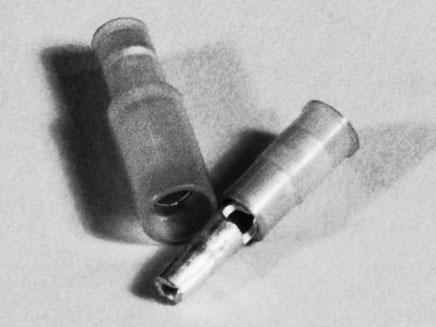
Fig. 9-3. Heat-shrink-type crimp connectors. These are expensive, but worth every penny if you can get your hands on them.
Dedicated Bilge-Pump Switch Panels
Now that you’ve got some of the basic supplies assembled, decide if you want to tie this new circuit into the distribution panel or connect it directly to one of your batteries with an optional, dedicated bilge-pump switch panel, as shown in figure 9-4.These switch panels offer an integral fuse and a choice of manual or automatic operation. The better units (as shown) also have a pilot light that lights up when the circuit is on. Be careful here, though: I have found many of these switch panels with 10-amp fuses installed in the holder. If you have one of the smaller pumps, this is a problem; they often require as little as a 1.5-amp fuse. A 10amp fuse would never do for a pump with a locked rotor; the fuse would surely allow the pump to burn up. Always double-check the fuse rating when installing one of these switch panels.
Although the bilge-pump switch panel described above could be made from various off-the-shelf components by a boatowner who had the inclination and time to do it, these assemblies are so reasonably priced that I generally use the standard switch panel—after making sure the fuse is adequate, of course.
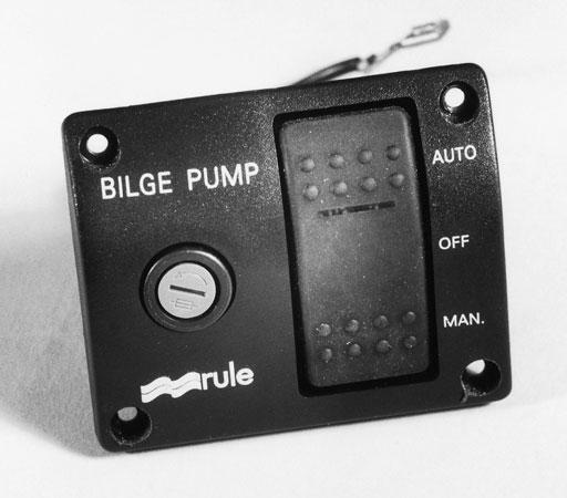
Fig. 9-4. Bilge-pump master switch panel.
Connecting the Pump to Power
There are several points to consider as you determine where you want to connect your new bilge pump to a power supply. If you connect it to the main distribution panel, the pump will be off when the master switch is thrown. This might be fine for a boat on a trailer, but less so for one kept at the dock or on a mooring where the pump needs to be on while everything else is off.
Often pumps are connected directly to the battery and fed through a dedicated switch panel (described above), but loading up a series of connections directly to the battery is simply not good practice. The ABYC suggests that no more than four conductors be attached to any one terminal. If your battery has a stud-type battery post, you’ll be limited by that restriction. Also, locating fuses near the battery is a mistake due to the potential accumulation of corrosive vapors near the batteries. The resulting corrosion of the fuse and fuse holder can cause excessive voltage drop and all the problems associated with it.
I’m not suggesting that you not attach your new pump directly to the battery—it is often the best option—but if you do, use the ABYC standard to your advantage. You can mount the fuse as far as 72 inches away from the battery (as long as the wiring is sheathed in addition to its insulation) and still be in compliance with the standard.
Another option is to use a single appropriately sized wire to feed an auxiliary fuse panel connecting all the onboard equipment you want, feeding directly from the battery rather than through the main distribution panel. Locate it far enough away from the battery to avoid the corrosive fumes but close enough to comply with the ABYC standard. Companies like Ancor, Newmar, and Blue Sea Systems make perfectly suitable fuse panels for this purpose.
Automatic Float Switch
Once you’ve decided how you’re going to provide power to your new circuit, you need to decide if you want to install an automatic float switch for your new pump. Since most installations do use an automatic float switch of some type, I’ll illustrate that setup here.
Figure 9-5shows the basic parts to this new circuit laid out and ready for the installation of the pump and the switch.
Tools
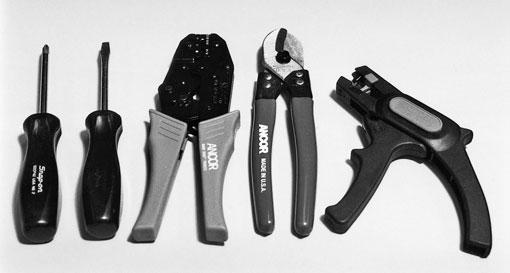
Tools you’ll need for this installation will include the following, some of which are assembled in figure 9-6:
a wire cutter, a wire stripper, and a set of quality crimping pliers (described in chapter 1)
a heat source for shrinking the heat-shrink tubing (a Bic lighter will do the job, but a heat gun is better, and safer)
slotted and Phillips-head screwdrivers to match the screws you’ll use to mount the panel, float switch, and pump assembly
an electric drill with an assortment of drill bits
a small saw—either a hole saw or an electric jigsaw, depending on how you decide to mount your master switch—to cut out a hole for the switch panel
Last, but certainly not least, you’ll need a wiring diagram to help you lay out your new bilge-pump circuit. All of the major manufacturers of bilge pumps and switch panels supply this vital information as part of their installation instructions. They’ll often include a recommended wire gauge to use for a certain length of wire run, saving one step in the installation process. However, I have noticed that the recommended wire size provided by some manufacturers of bilge pumps tends to be larger than what is allowed by the sizing chart in figure 4-7. My advice here is clear: for warranty and liability reasons as well as your own peace of mind, whenever there is a disagreement or conflict among different sources of information, always go with the recommendations of the manufacturer, even if it seems like overkill. Remember, a wire that is too heavy will never do any harm (up to a reasonable point, of course), whereas a wire that’s too small can destroy your boat.
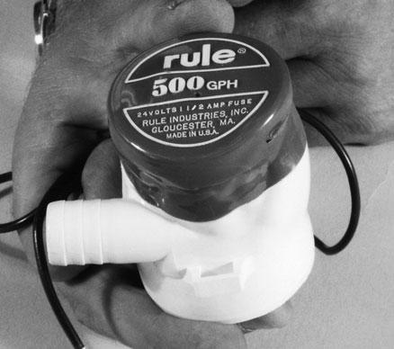
Figure 9-7shows the diagram that comes with a popular pump assembly available from Rule Industries.
The pump motor shown here is, like most bilge pumps, polarity sensitive. Reversing the positive and ground return wires on the pump motor will cause the pump to run backwards. Most bilge pumps (but
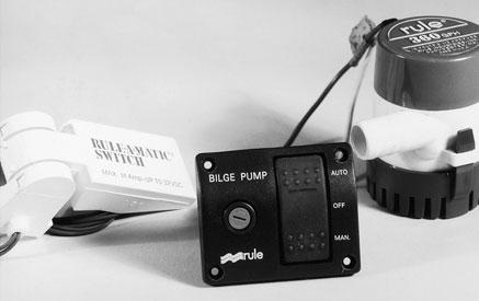
Fig. 9-5. Basic circuit components. Fig. 9-6. Electrical tools needed for a bilge-pump installation.
Panel Switch Float Switch
Fig 9 - 7
Battery
Fig. 9-7. Wiring diagram for a bilge pump.
Bilge Pump


