4 minute read
Engine Ignition Switch


is a series of individual wires wrapped in electrical tape or plastic tie-wraps, you should be able to trace the harness and find the break. Repair or replace the wire as required. If you get a resistance reading near zero, showing continuity, the problem is within the remote-control unit and must be fixed by your dealer.
Figure 8-8shows the extension harness being tested with a multimeter.
Advertisement
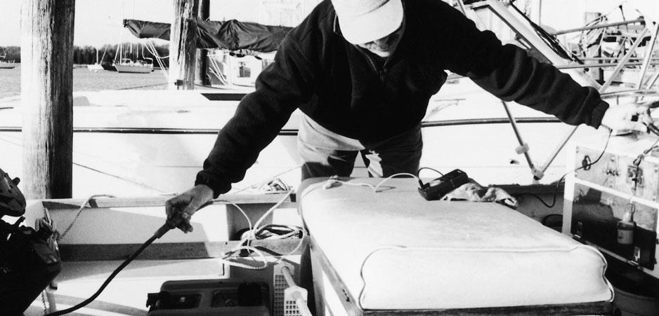
Testing for neutral-safety switch maladjustment is quite simple. Hold the shift-control lever with one hand and the ignition key with the other. Hold the key in the start position and gently work the shift lever to its extremes in the neutral position. (Never try to shift into gear without the engine running; you could damage to your shift mechanism.) If you hear the starter motor try to engage, then the switch is out of adjustment or the remote-control mechanism is badly worn and will need to be serviced by your dealer. Don’t be surprised if the control mechanism needs to be replaced due to excessive wear of the internal parts. This is not uncommon on older units.
Like the neutral-safety switch, most ignition switches are located inside the remote-control unit described above. This makes testing difficult, but some of the same procedures you used to test the neutral-safety switch also apply to the ignition switch. Essentially, you’re testing for battery voltage at the switch and for continuity to the solenoid. This can be done outside the remote-control unit up to the main plug assembly on the control unit. If the wiring harness connecting the engine to the remote-control unit is in good condition, which can be checked visually by tracing it from the engine up under the coaming of the boat to the control unit, problems are probably within the remote-control unit.
All manufacturers provide good, functional descriptions of each terminal in the wiring-harness plug, and all provide a test sequence to verify continuity between the terminals on this plug with the ignition switch in different positions. However, a good quick check of these terminals can also be made using your multimeter.
Fig. 8-8. Checking the wiring harness for continuity between the remote control and the engine. In this picture I’ve disconnected the plug at the back of the ignition switch and at the engine, and am using my ohmmeter to check for breaks in the wiring harness.
First verify that you have 12 volts at the ignition switch. Use your wiring diagram to identify the power lead from the engine to the main plug on the engine side of the circuit. (This wire is usually fed by a jumper lead that comes from the starter-motor solenoid or from a junction box bolted to the side of the engine block.) This terminal will generally be much larger than the others. If you find 12 volts at this plug and the plug terminals are in good condition, it’s reasonable to assume that 12 volts is getting to the remote-control assembly and feeding the ignition switch.
In all cases there will be a wire coming from the remote-control assembly that provides 12 volts to the ignition module (CDI unit) on your engine. This wire activates the electronic circuitry within the module while the engine is running. Use your wiring diagram to identify this wire on your engine. Make sure the emergency-shutoff switch is off, and turn on the ignition key. A reading of 12 volts where this wire attaches to the ignition module tells you that this function of the ignition switch is OK. If you don’t get 12 volts here, you need to trace the main harness and look for any trouble spots; correct them as needed.
If no trouble spots are found, the problem is in the remote-control unit. A possible trouble spot could be the point where you drilled a hole through the harness when you were mounting that new rod holder or downrigger.
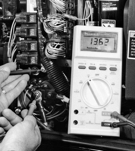
In addition to 12 volts at the ignition module when the key is turned to start and the shift in neutral, you’ll also need 12 volts at one of the small terminals on the solenoid. All manufacturers use a color-coded wire for this connection. (OMC and Mercury use a yellow-and-red one.) Remember that the black wire from the solenoid is a ground wire and not the one to check. Use the test described earlier to check for voltage at this point. If 12 volts is found while the key is in start, you know that the ig-
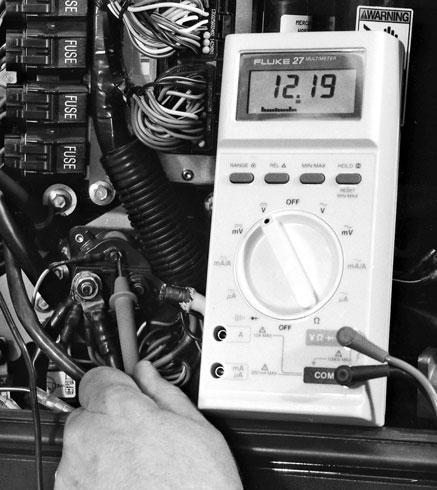
Fig. 8-9a. Checking voltage supply to an outboard-engine solenoid with the key in the start position. Remember, with the key in the start position, if the engine is cranking, the voltage reading will drop down to as little as about 9.6 volts. Fig. 8-9b. Checking voltage at the outboard solenoid with the key in the “on” position. With this test, you should get a reading near battery voltage.