6 minute read
Troubleshooting Starter-Motor Circuits


Starter Motor Solenoid Circuit Breaker
Starter Slave Solenoid
Advertisement
Battery
Ground Stud 90 Amp Fuse
Fig. 8-2. Typical MerCruiser starter-motor circuit diagram.
weakened by a sticking bilge-pump float switch or a light left on while the boat was unattended for an extended period is a common cause of an engine failing to start. Always be certain your battery is charged to at least 70 percent of its capacity before you assume that you have starter-motor problems.
If your boat doesn’t have a voltmeter to help you determine battery charge, use your multimeter and take a direct reading of open-circuit voltage at the battery, using the Open-Circut Voltage versus State of Charge table in the Open-Circuit Voltage Test section on page 84. If your battery is low, you will, of course, have to find out why, and the steps outlined in chapter 5 will help you to isolate the cause.
Once you confirm that the batteries are not the cause of your starter problems, you should begin troubleshooting. Have the workshop manual close at hand so you can identify all the circuit components for your boat.
As a first step, look at all wiring and connections to all starter-circuit parts. Tighten any loose parts and terminals, and clean any corroded terminals. Don’t forget to check the fuses and circuit breakers. A blown fuse or a tripped circuit breaker on a startermotor circuit could be caused by a partially seized starter motor or, in the worst case, a seized engine, both of which situations will be covered in more detail later on in this chapter.
If all connections and fuses or breakers appear to be in good order, a faulty part is certainly the cause for your starter-circuit grief, and a step-by-step approach will be needed to determine which part is at fault.
Starter Solenoid
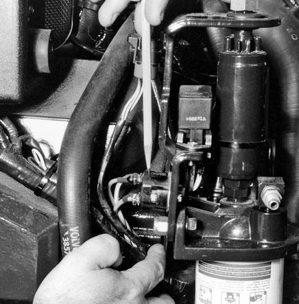
Most marine inboard engines have a remote solenoid, sometimes called a slave relay. A solenoid is used as a remote switch to control a circuit, such as your starter circuit, that carries heavy amperage. Acting as a shortcut, the solenoid is connected to the starter switch with a smaller wire to save on the amount of heavy wiring needed to operate the starter circuit. In other words, instead of having a cable as big as your thumb running from the battery to the ignition switch and then from the ignition switch to the starter motor, the heavy cable connects directly to the starter motor through a solenoid. The solenoid is operated by a much smaller (usually 10 or 12 AWG) wire that connects the solenoid to the ignition switch. Many starter circuits use a solenoid as a remote relay that does not carry full starter-motor current. To determine if your solenoid is intended to carry starter-motor current, first locate the solenoid. It’s generally cylindrical and is often found on a bracket at the top forward end of the engine. It will have two large wires and two small wires attached to it. Look at the size of the wire on the solenoid terminals. If the large wires are the same size as your battery cables (typically 4 AWG or larger), the solenoid carries starter-motor current. However, if the large wires are smaller than the battery cables—around the 12, 10, or 8 AWG range—the solenoid does not carry full
starter-motor current. The small wires are usually 14 or 12 AWG in both cases.
If you have a medium-to-large boat (over about 20 feet) with an inboard engine that does not have a remote solenoid, it will have one mounted on top of the starter motor. In this case, it will have only one large wire with one end connected to the solenoid and the other terminal connected directly to the battery or to the battery selector switch.
Solenoid Test
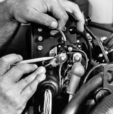
Testing a solenoid is really rather simple once you know what the four wires do. One of the large wires on the solenoid comes from the battery and the other goes to the starter motor. One of the small wires comes from the ignition switch, and the other, if there is one, connects to ground. Some solenoids are designed to ground through the case, and the bolt that attaches it to the engine acts as the ground. Figure 8-3ashows a heavy-duty solenoid; figure 8-3b shows a similar solenoid that does not carry full starter-motor current.
To test a solenoid, first make sure that the ignition switch is delivering battery voltage to the solenoid and that the ground to the engine from the solenoid is in good order. You’ll need your multimeter set on the DC volt scale to do all of the following tests except the ground-continuity test.
Use your multimeter set to the ohms scale you used for testing continuity to make sure the ground from the relay to the engine is in good order. Connect one probe to the solenoid terminal with the black wire (the red probe will be fine, but it doesn’t matter when checking continuity) and connect the remaining probe to ground. You should have a reading of almost zero ohms, and if your multimeter is equipped with a beeper for continuity, it should beep. If you don’t find continuity, clean the terminals at the relay and engine, then recheck. If the problem persists, install a new ground wire. Figure 8-4on page 127 shows the ground being checked with a multimeter.
Once you have verified continuity to ground, check the power lead on the solenoid for battery voltage. The power lead will almost always be a large red wire, but verify the color on your wiring diagram.
Fig. 8-3a. A heavy-duty remote solenoid. Fig. 8-3b. A light-duty relay.
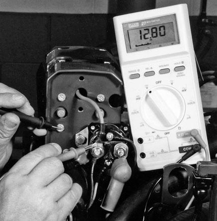
You might need a helper to turn the ignition switch while you check the meter. Connect the meter as shown in figure 8-5with the red probe attached to the red wire and the black probe connected to ground. Next, have your helper turn the ignition switch to start. If your boat has a starter button separate from the ignition switch, turn the key on before pushing the starter button. Make sure the transmission shifter is in neutral. You should get a reading of approximate battery voltage as the engine cranks. If you don’t find battery voltage and the engine won’t crank, there is an open circuit, which could be caused by a blown fuse, between the ignition switch and the relay.
A third wire on the relay will have battery voltage present with the key on. In some cases this terminal will be hot whenever the battery master switch is on. If not, trace this wire back to its source and repair the open circuit. Use your wiring diagram to determine where the wire is connected to power.
If battery voltage is present, determine if the remaining wire on the relay has battery voltage with the key in the start position. If it does, your starter-circuit problems have nothing to do with the solenoid or any of the wires going to it. If it doesn’t, the solenoid is faulty and must be replaced.
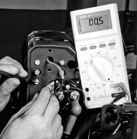
Fig. 8-4. Using an ohmmeter to check ground continuity at the solenoid. Fig. 8-5. Checking for voltage supply to a starter-motor solenoid. You should get a reading of approximate battery voltage here.
Current-Draw Test
Measuring the current drawn by the starter motor as it operates will give you some important information. However, specifications for the amperage drawn by different makes and models of engines are difficult to come by. Manufacturers usually don’t provide these data even in their workshop manuals. As a means of estimating current requirements for starter motors, mechanics have for years used 1 amp for each cubic inch of engine displacement as a starting point for gasoline engines. Diesel engines operate with much higher compression ratios, so a diesel starter motor might draw as much as 2 amps per cubic inch of displacement. Both these values are only good for very rough estimates of startermotor current. Gear reduction starter motors, which have become increasingly popular in recent years, typically draw much less current than do direct-drive motors—about half, for a two-to-one reduction ratio.