8 minute read
Final Checks and Ignition Timing


disconnect this wire from the back of the ignition switch and recheck the meter reading. If the meter now reads infinity, the ignition switch is faulty and must be replaced.
If the meter reading has little or no resistance, it indicates a complete circuit to ground, meaning the wire that connects the ignition switch to the engine is shorted to ground and must be repaired. If all of these readings check out, turn off the key switch and check your meter. You should have a low resistance reading near zero ohms. If your meter still gives a reading of infinity, check that the ground for the key switch is connected and in good condition. If it is, you may have a break (open circuit) in the wire leading from the switch to the terminal on the engine. Check the entire length of this wire for a break and either install a new wire or splice the break.
Advertisement
Figure 7-20shows a typical wiring diagram for a remote-key installation with the typical test points shown and the possibly faulty wires indicated.
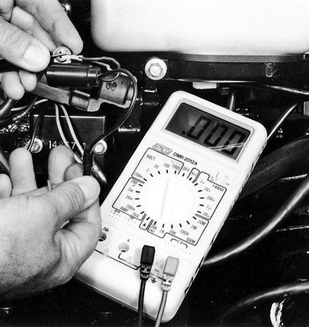
If after testing the stop circuit you still have a problem with your engine not shutting down with either the key switch or the stop button, the fault is in the CDI unit itself. Unfortunately, it’s a solid-state sealed device and is not repairable; it will have to be replaced. Mercury Tilt-Stop Switch Testing Some mid-sized and larger outboards have a switch designed to cut out the ignition if the engine is trimmed up too much. It’s located in the trimmounting bracket assembly. The tilt-stop switch prevents the lower-unit water-pickup port from raising out of the water enough to cause inadequate water flow. Figure 7-21shows this switch on a 70horsepower Mercury outboard.
To test the tilt-stop switch, remove the mounting screw that secures it to the engine. Disconnect the
Remote control with key switch and neutralsafetyswitch Remote control harness plug Battery, Positive cable Electrical junction 12 volt
Battery
Battery, ground cable
Starter Ignition motor module
Solenoid
Engine ground Fig. 7-20. Typical wiring diagram for an outboard-engine remote-key installation. remaining lead coming from the switch. Now with your multimeter set to the low-ohms (R × 1) scale, connect the meter probes to the two switch leads (it really doesn’t matter which probe goes where) and position the switch in your hand as it would normally rest on the engine with the trim down. The switch should be open, and the meter should read no continuity or infinity. Next, tilt the switch in your hand and tap the high end of the switch with your finger. The switch should close, and the meter should now indicate continuity through the switch. If your test readings are not as described here, replace the switch. Final Checks and Ignition Timing It is possible to thoroughly test all of the ignition parts, have everything check out, and still not have
Fig. 7-21. Mercury tilt switch. This switch is designed to prevent engine starting with the prop out of the water. If it malfunctions (open-circuits), your engine won’t start with the prop in the water, either! In this picture I’ve removed the switch and am testing its function with a multimeter set to check continuity when the switch is tilted manually. I’m verifying with the meter that the switch turns off and on.
any spark. Or you might have a strong spark and an engine that backfires when you try to start it or one that misfires at high speed. Your ignition system could still be the culprit. Before blaming the CDI unit or ignition-control module for a no-spark condition or bad timing (the backfiring), there are several additional things to check.
First, be absolutely certain that all wires are hooked up correctly. It’s all too easy to cross plug wires, or switch primary-feed wires going to the high-tension coils so that the CDI unit sends its signal to the wrong coil. Double-check everything against your engine-wiring diagram. Gang-plug connections are always keyed so they only go together one way, but it’s easy to make a mistake on engines with individual terminals. To avoid the possibility of crossfire between cylinders, make sure that all high-tension leads go into the proper hold-down clamp on the engine.
Loose-Flywheel Check
Next, consider the flywheel. Remember that it has carefully positioned magnets attached inside. The flywheel is keyed to the crankshaft so that these magnets pass the appropriate charge or trigger coil at a specific point in the engine’s rotation. On rare occasions, usually after the flywheel has been removed and improperly reinstalled, the flywheel becomes loose on the end of the crankshaft and shears off the key. The flywheel may spin independent of the crankshaft and change position of the magnets relative to the crankshaft, ruining the ignition timing.
To check for a loose flywheel, disconnect the master plug to the ignition module to disable the ignition system; you don’t want the engine starting with your hands on the flywheel. Next, grasp the flywheel firmly with both hands and feel for any side-to-side or upand-down movement, as shown in figure 7-22.Any movement indicates a loose flywheel. An experienced mechanic must remove the flywheel, and the crankshaft and flywheel must be inspected and repaired or replaced as needed. With luck, you’ll just need to install a new key and to re-torque the flywheel.
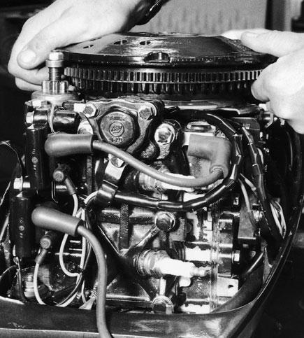
Fig. 7-22. Checking for a loose flywheel.
Timing Check
If all wiring is properly connected and your flywheel is secure, a timing check is in order. This is not a procedure for the inexperienced outboard-engine mechanic. The procedure varies somewhat for every outboard made, and verifying the position of the ignition-timing pointer is a precise and difficult job requiring special tools that the average boatowner won’t have. The timing should be checked at idle and for maximum advance at high speed. This is best done in a special test tank or with the aid of a dynamometer specially designed for outboard engines. The average boatowner doesn’t have these tools.
If you’re well equipped and have a reasonable amount of engine experience, you can set the timing by following the procedure outlined in the Engine Synchronization and Timing section of your workshop manual. On smaller, single-carburetor engines, the procedure is not especially complicated, and by following the instructions carefully someone with limited experience can do it. On the larger engines of over 25 horsepower, do-it-yourself is not recommended. The variables here are many and go beyond the scope of this book.
To sum up timing and its importance in ignitionsystem diagnosis, remember these important facts: Timing will rarely change unless someone alters the carburetor linkage or adjustments. Or the flywheel comes loose from the crankshaft. Or the flywheel magnets become unattached from the underside of the flywheel (a fairly common problem on some engines). Or the engine has many hours on it, and the timing plate under the flywheel is worn and has excessive play.
So if no one has tried to adjust your carburetors, and your flywheel isn’t loose, it’s highly unlikely that your ignition timing has changed. But if you have any doubts based on all the information presented here, get your timing professionally checked.
More on the CDI Unit
If your engine has been intermittently quitting or intermittently losing rpm, there is still a remote possibility that your CDI unit is acting up. Unfortunately, questions with the CDI unit may require you to rely on your dealer’s expertise for some tests, particularly on mid-sized to larger outboard engines. However, if you have a no-spark condition, and you have carefully performed all of the tests outlined above, you can feel quite comfortable purchasing a new CDI unit and installing it. That was your problem.
Other problems with the CDI unit are a little more difficult to pinpoint. Your system may have a builtin rpm limiter, or a slow-down circuit designed to reduce engine rpm if the engine overheats. If all of your other tests point to the CDI unit in anything other than a no-spark situation, inform your dealer of everything you have done and rely on the dealer to make the final decision on replacing the CDI unit. Dealers will not accept returns on electrical parts, so trial-and-error methods of testing can be expensive.
Optical-Timing Systems
If you own a medium-to-large outboard made within the last several years, you may have a subsystem integrated into your CDI unit called optical timing. This is a very sophisticated system that electronically controls the timing advance and retards the spark for easier starting. Unfortunately, troubleshooting this system requires an arsenal of specialized test equipment and adapters. If your engine has an optical timing system, consult your dealer for diagnosis once your problem goes past checking the fuse, spark plugs and wires, coils, and looking for corroded or loose connections, all of which I described earlier in this chapter.
To sum this section up, remember these important facts. Most problems with ignition systems will be visible—a broken wire, a corroded connection, or bad spark plugs that should have been replaced. Also, because of the variety of engines and ignition systems, you must use this book together with the service manual for your engine.
If you follow the guidelines and the simplified test procedures in this chapter, you’ll be able to pinpoint and repair the most common (and some not-socommon) ignition-system problems. If your tests lead you to a difficulty that must be handled by the dealer, you’ll have saved the labor dollars you would have spent for the tests.


