
19 minute read
Outboard and PWC Ignition Tests


Fig. 7-11a. Surface gap and traditional spark plugs. Fig. 7-11b. A spark-plug gapping tool.
Advertisement
duces electrical current. The more windings, the more current is produced.
As the secondary voltage leaves the center tower of the ignition coil, it travels through the spark-plug wire (the high-tension lead), which is heavily insulated and designed to carry high voltage. If all is well, the high voltage will jump the gap between the center electrode of the spark plug and the ground electrode, completing a circuit to ground. On larger engines with surface-gap plugs, the side of the spark plug is the ground electrode. Figure 7-11ashows both plug types. Figure 7-11bshows a spark-gapping tool being used to adjust the electrode gap.
Engine Stop Control
Last, but certainly not least, is the stop control—the device you use to shut off your engine by disabling your ignition system. Depending on the engine, the stop control might be activated by a simple stop button or, on larger engines, by a key switch. On newer engines, you’ll find an emergency-stop button with an overboard clip and lanyard wired directly to your system’s CDI unit. When the lanyard is pulled, the clip is yanked out of the stop button. This creates a momentary short circuit inside the CDI unit that diverts the voltage intended for the high-tension coils directly to ground and shuts off the ignition long enough to stop the engine. These stop circuits can cause a lot of problems, and procedures for testing them will follow a little later in this chapter.
Outboard and PWC Ignition Tests
The first step with all electrical-circuit testing is to carefully use your eyes. Look for the obvious! Whenever a problem develops with any engine or system that has been regularly maintained, troubles are almost always due to some minor oversight and are easily solved. Check all the wiring for any loose connections on your engine. Look for signs of corrosion on terminals and connectors. Check for any broken or frayed wires. Make certain the problem is not something as silly as a blown fuse. Any of these things can be the cause of ignition problems, and they can be quickly fixed with basic tools.
Testing for Spark
As with the inboard systems, the first step in troubleshooting your ignition system is to verify that you’re getting spark. However, with outboard and PWC systems you need to check each cylinder because each cylinder has its own high-tension coil, and partial system failures of one cylinder are not uncommon. When checking the coils, it’s extremely important that you check for any fuel leaks and make certain that all fuel line fittings and connections are secure.
It is a good idea to create some shade near the
Adjustable Knob
Attach to ground SE 30
020 4 0
Spark arcs here
Spark Plug Wire attaches here
Fig. 7-12. Snap-On spark tester. I prefer this type over all others because it’s adjustable, which gives you the ability to determine the strength of the available spark.
spark-plug wire you’re checking. It’s very difficult to see a spark jump a gap in bright sunlight. Use the spark tester shown in figure 7-12.Adjust the knurled knob on the tester to give an air gap of about 3⁄8 to 7⁄16 inch between the two pointed contacts inside the cylinder. Figure 7-13shows the spark tester properly connected and ready to go. Hold the tester so you can see inside the cylinder as shown, and crank the engine. You should see a bright blue spark (not yellow) jumping between the two contacts. If you do, then ignition output is satisfactory. If not, further investigation will be needed.
If your engine is skipping or misfiring, check all of the spark-plug wires this way to be sure that each secondary coil is sending a spark through its respective plug wire to the spark plug. The beauty of this spark tester over similar tools is that the air gap between the two contacts is adjustable. This is important because some manufacturers will give an air gap specification in their manuals. The wider the air gap a spark will jump, the higher the total ignition-system output. So, by comparing the maximum gap that a spark will jump for each ignition coil, you can find a weak or faulty coil.
Be careful not to get the spark plug wires mixed up when you do this test. Each wire is timed to a specific cylinder and must be replaced on the same spark plug from which you removed it. If you don’t see a spark, check the fuse for the ignition system and replace it if it is blown. Also, if you have one, make sure the emergency-stop button and clip are set correctly. It’s amazing how easy it is to forget this simple device. Check for spark again; if it’s still not evident, further investigation will be needed.

Fig. 7-13. Spark tester in use.
Checking the Spark Plugs
Just because you’re getting adequate spark to the spark plugs doesn’t mean the spark plugs are firing. They could simply be worn out, but there are many other things that can cause a spark plug not to fire. An oil blend that’s too rich (too much oil in the gas), a weak spark to a given cylinder, incorrect heat-range spark plugs, and fuel system problems are just a few. If you have regularly serviced your engine, worn-out plugs should not be a consideration.
So,what’sleft?Lookattheplugsandverifythat theycanactuallyfire.Removetheplugusingaratchet andspark-plugsocket,orusetheplugwrenchsupplied inthetoolkitforyourengine,andlookitover.The plugshouldnotbesoakedwithblackfuel-oilmixture. Arethecenterandgroundelectrodesintact?Ifnot, throwawaytheplugsandputinanewset.
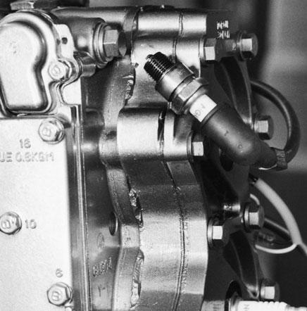
Fig. 7-14. Testing a spark plug to see if it fires.
If the plug’s center and ground electrode are OK and the plug is gapped correctly, check the number on the plug and match it to the manufacturer’s recommendations. It may be the wrong heat range for the engine. If all of these things check out OK, insert the plug into the correct plug-wire boot, wedge the plug into a spot on the side of your engine, as shown in figure 7-14,being sure that the metal case of the plug is grounded, and crank the engine. If you see a blue spark jumping from the center electrode to the edge of the plug on a surface-gap plug or to the ground electrode on a standard plug, the spark plug is OK and should fire in the cylinder.
If you don’t see a spark, or if you see a weak yellow one and you’re sure that adequate current was getting to the plug, the plug must be replaced. If it’s a standard plug, check the gap before installing the new plug as shown in figure 7-11b on page 112. Surface-gap plugs require no adjustment.
Spark plugs are among your most valuable diagnostic tools. Whenever you remove your plugs, keep them in order for the cylinders they came from. Check each plug; carefully look for cracks in the ceramic insulator body, black oily buildup, or discoloration on the electrodes. A spark plug that’s burning correctly will show a light brown “fluffy” coloration on the center electrode and a fluffy black coloration on the metal base. The ground electrode will be a light gray-brown color.
One last thing regarding spark plugs: be careful not to over-torque when reinstalling them into the cylinders. It’s a good idea to put a light coating of white grease on the threads before screwing the plugs back into the cylinder head. Screw them in by hand until the sealing washer seats; then use your sparkplug wrench or a socket and ratchet to tighten them an additional half to three-quarter turn. Any more torque than that could damage the plug threads in the cylinder head. You should never replace just one plug. Replace them in sets and don’t bother saving the old ones for use as spares. (They actually make good sinkers for offshore fishing.) You should always have a fresh set of gapped and ready-to-go plugs on board your boat—just in case.
Ignition Problem Quick-Check List
If you have checked the spark plugs, as described above, and determined that you don’t have a spark at any of the cylinders, or you have a spark at some cylinders and not at others, further investigation is needed. The following list will help organize your search through the ignition system, and the accompanying tests will help you to pinpoint the source of a problem. These tests should only be completed using this book and the manual for your particular engine. Each manufacturer uses different color coding for wires and slightly different test procedures for their respective systems. However, by following this guide you should be able to trace your way through your system and isolate any problems in the CDI unit in the rare instances when you have a problem.
These tests assume that you have eliminated any possibility of a problem with fuel or compression. The sequence for testing your outboard or PWC ignition system is as follows. 1. Check to see if your engine has a fuse for the ignition system. If it does, check the fuse and replace it if it’s blown or corroded.
2. Check the spark-plug wires. 3. Test all the ignition coils. 4. Do a water-spray test of the engine. 5. Test the charge and trigger coils and output to the CDI unit using your multimeter and Mercury DVA tester (part number 91-89045). 6. Test all engine stop circuits. 7. Test the tilt switch, if your engine is equipped with one.
Let’s discuss the details for each of these procedures in a little more detail.
Testing Spark-Plug Wires
Testing spark-plug wires is easy. If you have already used the spark tester and seen a spark at the end of the spark-plug wire, you know the wire is conducting electricity to the plug. But that’s not all the wire has to do. It also has to insulate this electricity under all engine-operating conditions and conduct electricity when your boat is underway and the engine is vibrating. Look at the wire and the wire ends inside the protective boots. Look for any sign of cracking, worn insulation, and any sign of green corrosion on the metal clips that lock the ends of the wire to the coil and spark plug. If you find corrosion, slide the boot back onto the wire and carefully clean the connector with a wire brush until the metal is bright and shiny. If the wire is chafed or cracked, replace it.
To check the wire electrically, set your multimeter on the low-ohms scale and insert the meter probes into the wire as shown in figure 7-15.The meter should read near zero ohms, except on some of the newest engines, where “resistor-type” wiring is used, in which case some resistance will be indicated on your meter. Next, hold the probes in place and bend and flex the wire while carefully observing the meter. If the reading fluctuates, there is a break in the wire inside the insulation. Replace the wire.
When reinstalling ignition wires, make sure to use the hold-downs found on many engines. These hold-downs keep the wire from coming in contact with moving engine parts that may chafe the wire and ultimately cause it to fail. Apply a light coating of waterproof grease to the ribbed ceramic insulator and metal connector of the spark plug and coil connector before reinstalling the spark-plug wire. The grease will help the boot to seal out moisture that would eventually corrode the metal connector on the end of the wire.
Fig. 7-15. An ohmmeter test of a spark-plug wire. Depending on your engine type, you may or may not measure resistance of any value when performing this test. With “resistor-type” wires used on some of the newest engines, readings of 5,000–10,000 ohms for each foot of wire length are not uncommon.
Testing High-Tension Coils
In the repair shop, a technician normally uses one of the testers specially designed to work with CDI systems. These testers are quite expensive and should not be a part of your tool collection, even though not having one will limit your ability to do advanced ignition-system tests. You can, however, do many tests with your spark tester, your multimeter, and a spray bottle filled with fresh water. These simple tests will enable you to narrow down possible causes of an ignition fault and in most cases
find the culprit behind it. At the very least, you’ll be able to point the professional mechanic in the right direction and save on expensive labor charges.
As already stated, each of your ignition coils is really two coils combined into one unit consisting of a primary winding and a secondary winding. The trick is to identify which external coil wires and connections go to which coil inside the insulated case. To do this you need the wiring diagram and workshop manual for your engine. Using the diagram in the manual as a guide, check the resistance of each of the coil windings with your multimeter’s ohmmeter. If you find electrical continuity and normal resistance, you can be reasonably certain your coil is OK. If you find excessive resistance, or if the meter indicates an open circuit within the coil, then the coil must be replaced.
Figure 7-16shows these tests on a typical outboard engine high-tension coil. Remember, though, that you must identify the correct wire connections and resistance values for these tests to work on your specific make and model of engine.
Whenever removing an ignition coil from your engine, carefully note the location of any insulating washers that you find under the coil or the holddown bolts. Misplacement of these washers can cause a no-spark condition with a perfectly good coil.
Fig. 7-16. Using the ohmmeter to test the resistance through an outboard-engine ignition coil: testing for a short circuit to ground (top) and testing resistance through the coil windings (bottom). Make sure to get the proper specifications for your engine from the workshop manual.
Water-Spray Test
Another simple test for determining the integrity of your secondary ignition system is to run the engine and use a spray bottle with fresh water to wet the area of the ignition coils, spark-plug wires, and spark plugs. Do this in the shade or at dusk. Any weakness in the insulation of connecting boots, high-tension coil cases, or spark-plug wires will immediately show up as sparks jumping from the poorly insulated wire or connection. Any component that shows spark should be replaced.
Testing the Charge Coils
For these tests you’ll once more need to consult your engine’s workshop manual. Remember, your charge and trigger coils are located under the engine flywheel and you can’t see them without removing it. Removing the flywheel goes beyond routine testing, and is not within the scope of this book. You can, however, still test the charge and trigger coils for continuity and for a possible short to ground. You can also test for voltage using the Mercury DVA tester and your multimeter.
The charge and trigger coils are just like your hightension coil. They are made with a long, tightly coiled wire insulated from ground. Charge coils have higher resistance than trigger coils, so they can generate higher voltage than do trigger coils. This means the length of wire in a charge coil is much longer than that in a trigger coil and therefore has a higher resistance.
The wiring harness for these coils is always secured to the movable timing plate under your engine’s flywheel and usually exits from under this assembly on the starboard (right side looking toward the bow of the boat) of the engine power head.
Once you have located the harness and found all the wires that come through it, match the color coding on the wires to your wiring diagram and deter-
mine which wires go to and return from the charge and trigger coils. These wires often terminate in a gang plug that connects to the CDI unit. Disconnect this plug to continue testing.
To test the charge coil, set your ohmmeter to the scale for the expected resistance as specified in your engine manual. Insert the red and black test probes into the plug socket that matches the correct color wire and take a reading. Charge coils generally have resistance between 400 and 900 ohms. If the reading is more than that or if a reading of infinity indicates a break in the wiring, the charge coil is defective and must be replaced.
Next, check for a short to ground by removing one of the meter probes from the plug assembly. Now switch your meter to the high-ohms scale (if it’s not self-scaling) and touch the free probe to the metal timing plate to which the lead harness is secured. Any reading on the meter other than “OL” indicates a short to ground. The flywheel must be removed to correct the problem, which is either frayed or melted insulation or a bad charge coil.
To test the continuity of the trigger coil follow the above procedure for the charge-coil tests, only adjust your meter to a much lower resistance—between 15 and 50 ohms is usually about right. To test for a short to ground in the coil lead, set the meter on the same high scale as for the charge-coil short test. If your engine is equipped with more than one trigger coil, test them all.
Figure 7-17shows these tests and the point at which the wiring harness emerges from under the flywheel. It also shows the timing-plate assembly.
To test for voltage from these coils you need the DVA adapter shown in figure 7-18and available through outboard engine dealers. This adapter can be used with any system of this type and converts the AC voltage from your charge and trigger coils to a DC voltage your multimeter can easily read. Sufficient readings from 1 to 9 volts will not only attest to the performance of the coils but also verify that the
Fig. 7-17. Continuity tests through the trigger-coil test and the short-toground test. Again, you’ll need your workshop manual to get the proper specifications for these tests. magnets under the flywheel have enough magnetism. As you know, voltage increases in direct proportion to the speed of the engine and the strength of these magnets. To test voltage, plug the red lead from the tester into the DC volt socket on your multimeter and Fig. 7-18. DVA adapter.

connect the black lead from the tester to the ground or negative socket. Next, plug the red and black probes from your meter into the corresponding sockets on the DVA tester, and you’re ready to take a voltage reading.
To test the charge coil, set your voltmeter to a scale that will read about 400 volts. Typical readings at cranking speed for charge coils are between 150 and 275 volts. You must check the workshop manual for your engine to get the exact specifications. Plug the meter leads into the socket or connect them to the leads coming from the charge coil. Again, your manual will help you identify these two wires.
Crank the engine or use the pull cord to turn it over while you take a reading from your meter. You may need a second set of hands here. Some of the newest meters have a “peak-reading” button that will hold the reading until you can look at the meter. If your reading is within specifications, the charge coil has tested OK and is not causing any ignition problems.
Testing the Trigger Coils
Next, test the trigger coil the same way you tested the charge coil, only switch your multimeter to a voltage scale of 20 volts or less. Typical trigger-coil voltage readings will be between 1.2 and 9 volts at cranking speed. Again, verify the specification in your engine manual. Make sure to check all the trigger coils if your engine is equipped with more than one.
Testing the CDI Unit
Next, using the multimeter and DVA adapter, test the CDI unit for voltage to each of the high-tension coils. Be sure the ground wire for your CDI unit is secure, as damage to the module could occur if it’s not. Use this ground to attach the black probe from your multimeter-DVA combination. It’s a good idea to use a wiring diagram to locate the stop circuit ground lead for your ignition module and disconnect it from the stop circuit; this isolates the CDI unit from that circuit and eliminates the possibility that a defect in the stop circuit could cause you to misdiagnose your CDI unit as faulty.
Next, switch your meter to a scale that will read about 400 volts (or allow it to self-scale). Locate the high-tension coil primary-feed wire, which is the wire that runs from the ignition module to the coil. Attach the multimeter’s red probe to the terminal on the high-tension coil, and crank the engine.
Your reading here, which should be somewhere between 150 and 350 volts, is the discharge from the capacitor inside the ignition module. Match your reading to factory specifications for your engine. Do this test on each lead coming from the CDI unit. Your readings should be approximately the same for each one. If you discover a lead with no output or a considerably lower output (check it against the specs in the workshop manual), the ignition module is defective and must be replaced.
Some of the latest CDI systems use a module with an integral trigger coil, and the module is located under the flywheel. In this case, you won’t be able to get at the charge coil to service it, and you won’t find any reference to trigger-coil testing in your workshop manual. The flywheel must be removed to service these parts; you’ll need the services of a dealer or another pro if your tests on the plugs, secondary wiring, and high-tension coil lead you this far.
Problems with charge coils, trigger coils, and the permanent magnets under the flywheel are extremely rare and something that you may never have to deal with on your engine. The only thing that usually causes early failure of these parts is accidentally submerging the engine in salt water and not properly cleaning it. A saltwater dunking will cause excessive corrosion in all the parts under the flywheel and, in most cases, ruin the engine if it isn’t tended to right away. If you should dunk your engine in salt water, flush it with fresh water and get it to your dealer without delay.
So, you have checked for spark to your spark plugs. You now know how to check your system’s spark with a simple spark tester. You can remove your plugs, check them, and replace them when it’s necessary. You can check your spark-plug wires and high-tension coils, and with the help of your workshop manual you can check your charge and trigger coils. Permanent magnets rarely lose their magnetism and don’t need to be checked. So what’s next? Your engine stop circuits and a few thoughts on some of the other functions your CDI unit may have.


