9 minute read
Shore-Power Battery Charging Systems and Installations


ber, this is a very low-amperage charging system—4, maybe as many as 9 amps are all you can expect. Operate the engine at a fairly high rpm; if the needle on the meter moves at all, your system is OK. If there is no movement, visually check all the electrical connections and terminals for corrosion and tightness. Clean and tighten them as needed.
If your system is equipped with a fuse, you should check it visually or test for continuity through the filament with your ohmmeter. Check your engine’s owner’s manual for the location of the fuse if you have one. If everything seems OK then the problem is probably in the rectifier.
Advertisement
Testing rectifiers is tricky without the wiring diagram for your engine. They don’t all look alike, and the wiring varies from one manufacturer to the next. The best approach for rectifier testing is to refer to your engine’s service manual. All you’ll need for equipment is your multimeter set to the diode-test scale.
If you test the rectifier and determine that it’s OK, you must next test the stator. These are all different, so work from your engine’s manual, and if you’re uncertain of the procedure, consult your local dealer.
Regulated Outboard Systems
Larger outboard engines (and, on the newest units, even the smaller ones) have voltage regulators installed into the circuitry. Sometimes these are combination regulator-rectifiers like you might find on an inboard system. If a component is going to fail in the system, it will most likely be this regulatorrectifier. The three-step voltage test described on pages 92–93 will work on these systems just like on inboard systems. It’s best to use your engine manual for the tests necessary to isolate charging system problems in the regulator.
Shore-Power Battery Charging Systems and Installations
Permanently installed battery chargers connected to your boat’s shore-power system fall into one of two general categories. The most common is the ferroresonant constant-output charger. The other is known generically as a smart charger or three-step charger. Many of the smart chargers available today also have a fourth stage known as an equalization stage and are thus four-step chargers. (More on that later.) A third popular type of battery charger is really a combined device known as an inverter-charger that not only converts 12-volt direct current into 120-volt alternating current, but also incorporates a quality multistage battery charger into one handy and compact unit.
As you’ll see in the following descriptions, the differences between the basic types of battery chargers are significant.
Ferro-Resonant Battery Chargers
Ferro-resonant battery chargers are deceptively simple devices, nothing more than a simple transformer (a ferro-resonant transformer) that converts 120-volt alternating current into 12-volt alternating current and a rectifier that converts the alternating current into direct current. The basic units, the simple household battery chargers sold at the auto parts store, work just fine for getting the car started on a cold morning or for a quick charge on a dead battery, but they have no place on your boat.
Ferro-resonant chargers designed for use on boats are a little more complex than the basic units. They incorporate some elaborate circuitry that will gradually taper the charging current to roughly match the demands of your battery. The better ferro-resonant chargers work fine on wet-cell batteries, but even the best don’t do a very good job with the new gel-cell and AGM batteries. In fact, many of the problems associated with premature battery failure, such as a rottenegg odor and boiling of battery electrolyte (the result of constant overcharging), are often caused by the use of the ferro-resonant chargers. Unfortunately, some of the largest producers of powerboats, such as Bayliner and Sea Ray, still install ferro-resonant chargers in their boats because they are considerably less expensive than newer smart chargers.
To determine which type of battery charger you have, you’ll need to find the charger itself. It will be mounted somewhere near the batteries. If you don’t see things like a battery-type selector switch or a temperature-compensation calibration switch somewhere on the charger, you probably have the ferro-
resonant type and should seriously consider an upgrade to a smart charger.
If you do have a ferro-resonant charger on your boat, make sure that none of your batteries are gelcells or AGMs. You must be able to check your battery electrolyte level regularly if you have a constant-rate charger. The tendency, particularly for people who plug into shore power and use their boats infrequently, is to overcharge the batteries and boil out the electrolyte. One trick used by many boatowners who have this type of charger is to leave on a DC-powered cabin light or two, even when they are away from the boat. This light puts a small drain on the batteries, minimizing the overcharging effect.
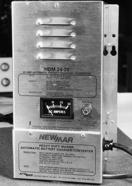
If you have a constant-rate charger, you should check all the cells in your batteries every two weeks or so and top them up with distilled water as needed. Batteries that run low on electrolyte will burn up in short order. Figure 6-12shows a typical constantrate charger. Smart Chargers
The newest wave of electronic battery chargers, generically called smart chargers, is a by-product of power-supply technology for computers. Smart chargers are small, reliable, and highly efficient. They are also extremely complex as compared to the simple ferro-resonant chargers, and I won’t even begin to describe their circuitry. Suffice it to say that they charge your batteries in precise steps, or phases, that are highly beneficial to the longevity of your batteries. More important, these steps are adjustable to accommodate the type of battery you have, making them the only choice if you have gel-cell or AGM batteries.
These new smart chargers are produced by a number of manufacturers and have really gone a long way toward maximizing the potential for the newest battery technologies, both gelled and AGMs. However, don’t for a minute assume that a smart charger will be a waste of money if you have standard wet-cell batteries. All batteries will benefit from using a smart charger. These chargers are available in a variety of configurations for single-, dual-, and three-batterybank installations and have amperage ranges from as few as 8 amps to as many as 130 amps for the largest inverter-charger combinations.
Fig. 6-12. A ferro-resonant charger. These constant-rate chargers have destroyed many a battery!
Phases ofBattery Charging
Unlike the ferro-resonant chargers that gradually reduce the charge rate along a rather steadily sloping curve as a battery comes up to charge, smart chargers use three and sometimes four distinct phases for revitalizing your batteries. 1. The bulk phase. The first phase of the batterycharging cycle is known as the bulk phase.
This is where most of the charging occurs. A discharged battery can accept a higher rate of charge, up to about 70 to 75 percent of the total charge, in the initial stages of charging than it can in the final stages. Typical charge rates during the bulk phase are 20 to 40
percent of the battery’s capacity in amperes with a voltage of about 14.4 volts. Gel-cells will charge at about 14.1 volts. When the battery is 75 percent charged, the smart charger automatically switches to the acceptance phase of the charge cycle. 2. The acceptance phase. The second phase of the battery-charging cycle is known as the acceptance or absorption phase. During this phase the voltage is maintained at 14.4 volts for wet-cell and AGM batteries and at 14.1 volts for a gel-cell. The charging amperage is gradually reduced until a rate of 4 percent of the battery’s capacity is achieved. Thus the acceptance phase for a 100-amp-hour battery ends when the charging amperage the battery will accept reduces to 4 amps. The smart charger automatically switches to the float phase. 3. The float phase. The final phase of a normal charging cycle is known as the float or finish phase, during which the smart charger reduces the voltage to 13.3 volts for wet-cells and
AGMs and 13.7 volts for gel-cells. Gelled electrolyte batteries typically have a slightly higher fully charged open-circuit voltage than their wet-cell brothers do. The float phase is more maintenance than an actual charge because it keeps the battery at a full charge without overcharging. This is the big difference between the smart chargers and the ferro-resonant units described earlier. 4. The equalization phase. The fourth phase of battery charging I want to discuss is really another maintenance phase and is only used on wet-cell batteries. In fact, use of the equalization phase is quite damaging to gel-cells and a waste of time on AGM batteries.
The equalization phase takes care of minor irregularities in specific gravity between cells that develop as a battery ages. As your battery gets older, the chemical reactions inside the individual cells can vary slightly with variations in the chemicals in the water you’ve added to the cells and with minor variations in the manufacturing tolerances of the battery. Lead-sulfate particles will eventually begin to cling to and build up on your battery’s cell plates. As this buildup continues, less and less of the battery’s cell-plate area is exposed to the electrolyte and the cell’s capacity is effectively reduced.
The equalization phase minimizes this premature buildup of lead sulfate by charging the battery at amperage equal to 4 percent of capacity until the voltage reaches somewhere between 15.5 and 16.2 volts. This controlled overcharge literally rattles the sulfate particles out of the battery plate, forcing them back into the electrolyte where they belong.
The danger with using the equalization phase is that you can do it too often. In some industrial applications, equalization is used as a part of every charge cycle because maximum battery “punch” is required. This is simply not the case on a powerboat, and you should equalize your batteries no more than three or four times per boating season.
Not all smart chargers offer an equalization phase. On those that do, it’s not automatic and must be selected manually.
Temperature Compensation
All of the smart chargers I have worked with have some form of temperature compensation built in to help the brain of the charger determine the proper charge rates. Three common arrangements are available. One method requires the installer to select a temperature setting from a selector switch mounted on the charger housing. Another uses automatic temperature compensation with a built-in temperature sensor on the charger. I feel that these two methods, although certainly offering a technological quantum leap from the ferro-resonant chargers, are still a bit lacking. The best sensing for temperature compensation can only be made at the battery itself. The temperature of the battery will change dramatically as it charges, whereas the temperature surrounding the charger itself may not if it’s mounted as it should be in a well-ventilated location.
The best chargers today use the third type of temperature compensation: a temperature sensor that’s mounted to either the side of the battery or inside the battery box. Always look for this feature when you upgrade your battery charger.


