5 minute read
Outboard-Engine Charging Systems


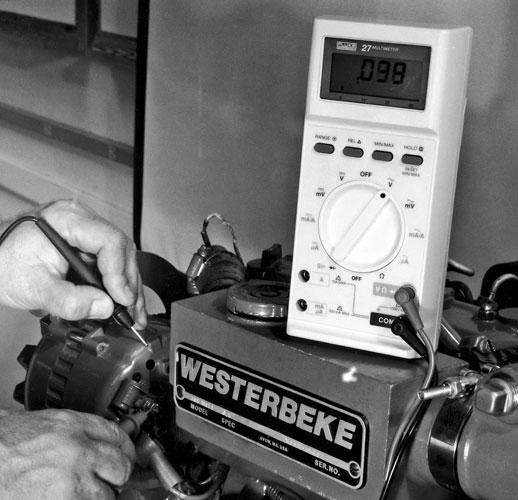
Fig. 6-10. AC ripple-voltage test. Your black meter lead should be connected to a known good ground and the red lead to the B+ (output) lead on the back of your alternator. Remember to make sure that your meter is set to the AC volt scale.
If you have one of the LED testers shown in figure 6-9,alternator testing is a one-step procedure. The tester has red and black leads and probes just like your multimeter. Attach the red probe to the B+ terminal at the back of the alternator and the black probe to a nearby ground (one of the alternator mounting bolts will do), and start the engine. Observe the LEDs on the meter. Any lights flashing or constantly lit indicate a problem with either the alternator or the voltage regulator (assuming the alternator is getting excitation voltage as described earlier). Follow the instructions printed on the tester to determine what course of action is required. Figure 6-9 shows the LED tester connected and ready to check a charging system. If you’re not sure which terminal is B+ on your alternator, refer to figure 6-1. If you don’t have the tester, you can do an alternating-current ripple test using your multimeter, as shown in figure 6-10.Connect your meter leads to the battery with the red probe to the positive post and the black probe to the negative post, and set it to the AC volt scale. Run the engine up to a fast idle, switch the meter to the alternating-current volt scale, and check the reading. You should have no more than 0.250 volt AC at the battery. If the reading you get is greater than that, the diodes in your alternator are defective and the alternator must be serviced.
Advertisement
Draw Test
The last test I will mention is the draw test. Particularly in the marine environment, it’s possible to get electrical crossovers from a hot wire to a nearby ground, causing a voltage leak that can drain your battery. Testing for crossover current is fairly simple, but a few precautions need to be mentioned.
You’re looking for a constant electrical draw on your battery. Make sure all the electrical accessories on your boat are turned off and the engine is not running. Make sure you have disconnected everything including any radios and stereos with memories and clocks that bypass the switches. Next, disconnect the positive terminal at the battery. Set your multimeter to read amps and connect it in series with the terminal end of the battery cable and the positive post on the battery. A reading of any significant amperage (over 0.01 amp) indicates something on board is draining your battery.
Now you must locate which circuit is the culprit. If your boat has fuses, isolate each circuit by removing the circuit fuses one at a time and checking to see if the amperage reading is eliminated or reduced. If you have circuit breakers, carefully turn off the breaker switches one at a time until the amperage reading disappears or decreases to practically nothing. Once you have located the circuit that’s causing the battery to be discharged, you should be able to troubleshoot the circuit just as I described above.
Outboard-engine charging systems come in two varieties: with or without voltage regulators. The unregulated systems have an alternator built into the top of the engine that puts out constant amperage of 5 or 6 amps (or more on newer, bigger engines) any time the engine is running. Regulated systems use a volt-
age regulator that’s similar to the one we discussed above. However, there are enough important differences to warrant a closer look.
Unregulated Systems
Smaller outboards from 6 to 10 horsepower usually do not have a voltage regulator. The charging systems on these small engines generally produce between 4 and 6 amps of current at maximum output. The problem is that even this small amount of current can be too much if the battery is charged and you aren’t using any electrical equipment. This constant charge creates a built-in overcharge that will boil away battery electrolyte. If you have one of these small motors, it’s critical for normal battery life that you check and top up the electrolyte frequently. You should never use anything but a wet-cell battery on these motors.
This nonregulated system consists of four major components plus the wiring that connects them all. On the top of the engine there are permanent magnets attached to the inside of the flywheel and a series of stator windings. When the engine is running, the permanent magnets spin very close to the stator windings and produce alternating current via magnetic inductance, just as it’s produced in the inboard alternator discussed above. This alternating current is converted into direct current that can be used to charge the battery by passing it through a diode rectifier that’s slightly different than a bridge rectifier.
This rectifier is not contained in the same housing as the alternator, as are the ones found on inboard alternators. It’s really nothing more than a group of diodes mounted in a heat sink that’s bolted to the engine block. The heat sink provides a ground and helps conduct the heat away from the diodes. Some makers of outboards also install a fuse in the circuit, so check your owner’s manual.
The last component in this basic system is the battery.
A common question regarding unregulated systems is whether they can be run without connecting the motor to a battery, without damaging the statorrectifier. The answer is that it depends. Some motors can be run without batteries, and some can’t. Follow the recommendations in your owner’s manual. Some manufacturers provide caps to cover the battery-cable terminals to prevent them from touching while the engine is running without a battery. However, some companies, Mercury for example, also recommend disconnecting the stator wires from the rectifier and insulating them from each other if you’re going to use their motors without a battery.
Figure 6-11illustrates a typical unregulated outboard charging system.
Stator windings
Rectifier Junction box
Fig. 6-11. Unregulated outboard charging system.
Testing the Unregulated System
From years of experience, I can tell you that the boatowner causes 99 percent of the problems that occur with these unregulated charging systems. Rarely is there any trouble with the permanent magnets or the stator windings under the flywheel. Problems are almost always due to corroded or loose connections or to a failed rectifier. As I’ve mentioned before, diodes are very sensitive; they hate it when battery wires are crossed or grounded unexpectedly.
So, how do we verify the system is producing charging voltage? It’s easy if you have one of the inductive ammeters described earlier: Simply clamp the meter over the positive battery cable with the engine running and rev the engine (don’t over-rev it). Most inductive meters work on a 100-amp scale, so don’t expect to see much needle movement. Remem-


