
15 minute read
Battery Installations


content (soft water) is fine for batteries; some is terrible. The best bet is to check with a local battery shop and ask about their experience with the local water.
Keep tabs on both your engine’s alternator and your boat’s 110-volt battery charger, if you have one.
Advertisement
Overcharging or undercharging is damaging to any battery. Overcharging will boil the electrolyte and rattle the lead off the plates. Undercharging will allow the lead sulfate to permanently harden, reducing the surface area of the plates. A sulfated battery will not develop full power and will eventually have to be replaced.
There are a number of ways to hook up and combine batteries. For the small, open boat, the choices are fairly simple and easy to understand. But, if your boat is a medium-sized cruiser with twin engines and both a bank of starting batteries (for starting the engines) and a bank of house batteries (for supplying your needs while away from the dock), the battery systems can get fairly complex. I will only attempt to present the most common systems here.
First, refresh your memory on series and parallel wiring hookups as we discussed back in chapter 1. These two methods of connecting battery cells and batteries are the primary methods builders use to alter system voltage and amp-hour capacity. Also, you need to know a little more about battery characteristics. To create a 12-volt lead-acid battery, manufacturers connect a series of six cells, which each produce a little more than 2 volts, to attain the 12 volts in batteries used by most boats. Larger boats might use 24-volt systems, and some boats even use a combination 12- and 24-volt system, but these are just 12-volt batteries connected in series to get the higher voltage.
When battery cells are connected in series, the voltage is multiplied. Thus, multiplying the number of cells in a lead-acid battery by two gives the final system voltage. If we hook these cells or batteries up in parallel, the voltage stays the same, but the amperage of the system is multiplied. Thus, if you have two 6-volt batteries with 25 amps each, wired in series, you’ll end up with a 12-volt bank having 25 amps of current available. If you wire these same two batteries in parallel, you’ll have a 6-volt system with 50 amps of current available.
The majority of recreational boats today operate on 12-volt battery systems, so we’ll stick with those. Figure 5-8shows two pairs of 12-volt batteries. One pair is connected in series, the other in parallel, and the resulting amperage and voltage of each arrangement is shown. This is very important. I’ve seen more than one boater trying to connect batteries in the spring, and they just can’t remember how they were attached when they took them out.
Here’s a quick tip to prevent this confusion: Simply mark the cables when you remove your batteries in the fall so you’ll remember how they go when you’re ready for your spring launch. Remember that connecting 24 volts to a 12-volt system can be a very interesting but very expensive mistake. The parallel hookup is not what you’ll find on your boat, as a bat-
Parallel Batteries
Series Batteries
Fig. 5-8. Two 12-volt battery pairs, one in series, one in parallel. Remember that series connections combine the voltages of the batteries connected; parallel connections combine the available amperage but do not change the voltage.
tery switch will usually separate the batteries (unless, of course, you’re building a large battery bank from multiple batteries). I am just trying to illustrate what happens to amperage and voltage in these circuits.
Battery-System Components
Besides the batteries, other components found in any battery system are as follows: Every system will have cabling connecting the batteries to each other and to the distribution panel and starter. There will be a master control switch of some type to separate and isolate the individual batteries. In some cases a diodetype battery isolator is used to prevent batteries discharging into each other. And in some of the newer installations, a device called a battery combiner will be used to do the same thing. Naturally, all of these circuit components must be rated for the amperage they are expected to carry. Let’s go through this list and take a look at each component. Battery Cables
In the latest version of the ABYC battery standard, E-10, a major wording change has altered the requirements for cabling attached to battery terminals. It now states: “10.8.3. Battery cables and other conductors size 6 AWG (13.3 mm2) and larger shall not be connected to the battery with wing nuts. 10.8.4. Multiple conductors connected to a battery shall be installed with the highest ampacity conductor terminal closest to the battery, followed by successively smaller ampacity conductor terminals. 10.8.4.1. A maximum of four conductor terminals shall be permitted to be installed on a single battery stud. 10.8.5. Flat washers, if used, shall only be installed immediately under the split lock washer and nut of the attachment stud.” This whole matter of the wing-nut attachment has been a bit contentious for years. These wing nuts do have a tendency to loosen and this will cause the terminal connector to heat up excessively due to the inherent resistance that is created. This represents a fire hazard on board!
Battery cables are the extremely heavy wires that connect your batteries to each other and to your distribution panel and starter motor. They might also be used to connect other high-amperage equipment such as generators, anchor winches, and large inverters. The battery cables are by far the largest wires you’ll find in your boat. They are also among the most important and the most neglected. Most medium-sized and larger boats will use a variety of sizes of cables in the battery system. A medium cruiser, for example, might have AWG 00 cables the diameter of your thumb between the individual batteries and AWG 2 cables connecting the batteries to the boat’s systems. (In general, conductors larger than AWG 8 are called cables instead of wires, and the wire-end fittings are called lugs instead of terminals.)
Battery cables, as with any other wiring on board your boat, must be large enough to carry the current that the equipment connected to them will need. The size of battery cables is based on the maximum amperage that the starter motor and other high-demand equipment needs. Manufacturers generally do a good job of providing information on cable sizes in their workshop manuals.
The table belowshows minimum AWG cable sizes required for various installations. When using this chart to select cable sizes, the positive and negative cables must be the same size. Typically, the gauge of the wire will be embossed on the insulation for easy identification.
Battery Selector Switches
We have already established the need of larger boats, those much bigger than an open runabout, for a
Battery Cable Recommendations
AWG Gauge and Cable Length . . . . . . . . . . . . . .Metric Equivalent Up to 31⁄2 feet (1.1 m) . . . . . . . . . . . . . . . . . .4 (25 mm2) 31⁄2–6 feet (1.1–1.8 m) . . . . . . . . . . . . . . . .2 (35 mm2) 6–71⁄2 feet (1.8–2.3 m) . . . . . . . . . . . . . . . .1 (50 mm2) 71⁄2–91⁄2 feet (2.3–2.9 m) . . . . . . . . . . . . . . .0 (50 mm2) 91⁄2–12 feet (2.9–3.7 m) . . . . . . . . . . . . . .00 (70 mm2) 12–15 feet (3.7–4.6 m) . . . . . . . . . . . . . .000 (95 mm2) 15–19 feet (4.6–5.8 m) . . . . . . . . . . . .0000 (120 mm2)
combination of cranking batteries to start the engine and deep-cycle batteries to run the boat’s systems. The longevity of these batteries will be greatly decreased if they are used for the wrong application, so you need a means to select which battery is in use at the appropriate time. The very best way to do this is with a battery selector switch with the familiar “off,” “No. 1,” “No. 2,” and “both” switch positions.
These switches should be installed on any boat with an electric system, even if you have only a single battery. Of course, a single-battery installation doesn’t need the four-position switch. A simple two-position on-off switch will do fine. The ABYC recommendations exclude boats using batteries smaller than 800 CCA from the requirement for a battery isolation switch, so if you buy one of these smaller boats, you’ll probably have to install the switch yourself. Fortunately, it’s an easy and straightforward job.
A recent experience I had brought home the importance of being able to quickly shut down any boat’s electrical system in case of emergency. I was motoring across the bay when I noticed a small boat with smoke billowing out from under the port-side deck into the cockpit. I immediately altered course to investigate and found a fellow who was, along with his entire family, in a complete panic. The fire had been started by a severe short circuit, and the boat had no means of shutting off the electrical system. Current from the battery was feeding the fire, making it impossible to extinguish as long as the battery remained connected. There was no master switch of any kind. It was an all-too-typical situation of a single battery installed on a small outboard-powered boat. I jumped aboard the runabout and cut the positive battery cable with a cable cutter I keep on board for working with heavy shark leaders. The boat did have a working fire extinguisher aboard, and once the battery was disconnected we were able to extinguish the blaze in time to save the boat. Even so, I’m not sure if this fellow’s family will ever again go boating with him on any kind of boat.
This little melodrama points out how important it is to be able to disconnect the battery power when there is an electrical fire. It’s imperative to disconnect the power before you attempt to put out the fire. As long as there is battery current available, your attempts to stop the fire will be futile. A $40 switch could have saved this fellow hundreds of dollars in damage and made his family feel a whole lot better.
Some Typical Selector Switches
Let’s look at some typical battery selector switches and learn how to deal with them. My purpose here is not to attempt to show you every possible arrangement of batteries and selector switches, but to give you a good understanding of the key elements in some of the most popular circuits. Modification of these basic systems into more complex designs should not be too difficult once you understand the basic circuits.
The Guest Co., a major supplier of battery switches and components (now part of Marino), has some excellent diagrams available that could be quite helpful if you do decide to undertake a major system upgrade on your boat. Some examples of these diagrams follow in this chapter.
Battery selector switches have a continuous and an intermittent (sometimes called momentary) rating for amperage. The continuous rating is the amperage the switch can sustain while the switch is in normal use. The intermittent rating is the much higher amperage that a switch can sustain over a short period of time, usually measured in seconds. It’s important to know what these ratings are when you purchase switches for replacement of existing switches or for additions to your system. You can’t tell much by simply looking at the switch.
The battery switch you select must be capable of handling the extreme intermittent current associated with engine cranking and the maximum continuous current of the electrical loads in your system. Rating numbers look something like 230 amps continuous and 345 amps intermittent. Heavy-duty switches often have ratings of 360 amps continuous and 600 amps intermittent. Be certain that the switch you purchase is intended specifically for battery switching.
Battery switches available today have an important feature known as make before break. When switching from one battery to another, the contact inside the switch connects the battery you’re selecting before it disconnects the battery you’re deselecting. Without this feature your alternator could be destroyed in an instant. An alternator cannot stand
even a momentary disconnect from the battery it is charging without damage. Therefore, never shut your battery switch off with your engine running. An alternator is essentially a dumb device. Without the load of a battery on it while it’s running, it will automatically surge to its full output, burning out the diodes inside it.
Maintaining battery switches is not something many people think of, but the most common cause for failure of these switches is loose connections on the back of the switch. These loose connections cause resistance, which in turn causes heat. With starter-motor current trying to get through the loose connection, that heat is often enough to actually melt the plastic housing around the cable studs. This effectively loosens the stud in the case and destroys the switch. The answer here is to occasionally check the tightness of the connections at the back of the switch. In fact, some switch manufacturers even recommend using a specialized torque wrench to ensure proper tightness!
Battery Isolators
The next commonly found component in multiple battery systems is the battery isolator. By using these isolators correctly, we can eliminate the problem of batteries discharging into each other. Isolators use heavy-duty diodes, which only allow electrical flow in one direction, to separate batteries, preventing one from discharging into the other.
It’s important to separate batteries for several reasons. First, one of the characteristics of batteries is that a fully charged battery will try to recharge its weaker brother in a system. So, if you have a two-battery system and one battery is discharged with the battery switch left on “both,” the first battery will discharge into the second one until they reach the same voltage. The ideal system will prevent this, but it involves installing a battery isolator.
Battery isolators use a group of diodes, which are electrical check valves that allow electricity to flow in only one direction. Isolators are installed between the batteries on a system to prevent a charged battery from trying to recharge a discharged battery to which it’s connected. Isolators are an excellent addition to any low-end multiple battery installation. Figure 5-9shows a typical 70-amp, two-battery isolator.
Isolators need a little care, just like the other parts of your battery system. Isolators are rated to carry a maximum amount of amperage, so you need to select the correct unit for your boat’s system. Standard
Fig. 5-9. Typical battery isolator.
Fig. 5-10. Typical two-battery installation with isolator installed. Alternator Isolator
Battery Switch Starter Motor Solenoid
Parallel Batteries
ratings are 70, 130, and 160 amps. The rating you use should be, at a minimum, equal to your engine alternator’s maximum output capacity. Check the manual for your boat’s engine to get this specification. Isolators are also configured to be used with either two- or three-battery systems, so make sure you have the correct one for your system before you install it.
Figure 5-10shows a typical two-battery system with an isolator installed. The current flowing through the circuit shows the isolator effectively separating the two batteries so that one cannot discharge into the other.
Isolators have several faults that you need to be aware of before you buy one. First, the diodes used in them are electrically expensive. The big diodes have an inherent voltage drop of around 0.7 volt or almost 6 percent of the system voltage; this means that charging times will be just that much longer. The second problem with isolators is heat. All diodes produce heat—it’s where that 0.7 volt goes—and isolators are mounted on a substantial heat sink to dissipate that heat. This means that the isolator needs to be well ventilated, or heat buildup in the heat sink will destroy the diodes. The third problem is that on some isolators the heat sink is a part of the circuit and the entire thing is hot when the battery is being charged. This type of isolator must be mounted where there is no chance of any conductive material coming in contact with it, because otherwise an unfused direct short circuit can result. In spite of these faults, an isolator may be your best bet as an inexpensive way to keep your batteries from discharging into each other.
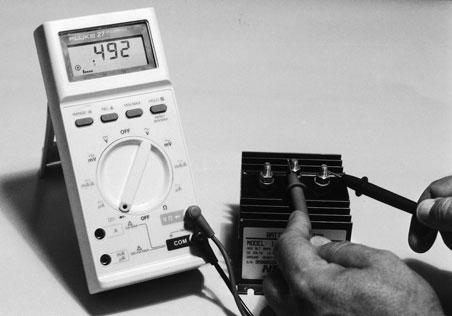
Testing Battery Isolators
Testing battery isolators to determine if they are functional is a straightforward matter. First mark and disconnect the cables connected to the isolator.
1 2
3
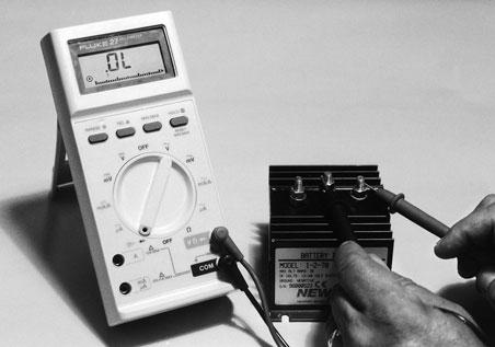


Fig. 5-11. The four steps to test a battery isolator.
4
Set your multimeter to the diode-check function and test for continuity in one direction through each diode and no continuity in the opposite direction. Figure 5-11shows the four steps required to test a typical isolator connected to one alternator and two batteries.
If you discover that you have continuity in both directions for any of the diodes in the isolator, or no continuity in either direction on any of the diodes, the isolator must be replaced. Repairs are not practical in the field. Also, alternators described as one-wire alternators won’t work with battery isolators without internal modifications to the alternator that must be done in a professional shop. One-wire alternators have been widely used by both MerCruiser and OMC.
Figures 5-12, 5-13, and 5-14show three typical multiple battery installations using the components described above. Figure 5-12 shows a typical singleengine, two-battery setup with a master switch and
Alternator
Alternator Engine #1 Alternator Engine #2
Isolator
Parallel Batteries
Starter Motor Solenoid Battery Switch
Alternator Engine #1 Alternator Engine #2
Isolator
OFF
ON
Battery Switch
OFF
Battery Switch
ON
Parallel Batteries
Ground Stud on Engine
Fig. 5-12. Single-engine, two-battery circuit with battery switch installed. Remember that battery switches must be matched to the maximum expected amperage they need to handle. Fig. 5-13. Similar arrangement, with the addition of an isolator.
Fig. 5-14. Twin-engine installation with two battery switches and an isolator.
Fig. 5 - 14 Parallel Batteries


