4 minute read
Measuring Amperage


Fig. 3-7. In checking source voltage at the back of a switch panel, remember to always verify your power source first when tracing circuits.
Fig. 3-8. Meter lead connections on a meter and voltage checks for three light-socket types.
Advertisement
testing. Sometimes you’ll be testing directly across switches and relays or from one end of a wire to the other, even though I said earlier that you shouldn’t do this.
Figures 3-9, 3-10, 3-11, and 3-12 illustrate the various meter-connection possibilities for this test.
Begin with the circuit you’re measuring turned off. The meter should be turned on, set to measure DC voltage, and if your meter is not self-scaling it should be set to the lowest voltage on the DC volts scale (usually 2 volts). Once the meter is connected, turn the circuit on and take a reading on your meter. The reading is the voltage drop at that point in the circuit. Record the reading.
Measure the voltage drop at each wire and connection in the circuit, including the negative return, then add up the results. The total of all these measurements must fall within either the 3 percent or 10 percent limit. Any reading that’s a lot higher than the others in the circuit indicates a point in the circuit with excessive resistance or voltage drop. Correct any problem by cleaning or tightening the connection, or by replacing the connecting wire.
As already discussed there are two methods used to test amperage. One method uses meter leads and requires the disconnection of the DC power lead for the circuit you’re testing (I discuss AC in more detail in chapter 11); the other uses a clamp-type inductive meter.
Using Meter Leads
Unlike voltage checks, amperage checks with a basic multimeter require that the meter be connected in
Fig. 3-8
Figs. 3-9, 3-10, 3-11, 3-12. Various hookups for checking voltage drop. In figure 3-12, the meter leads are shown as you would trace through a circuit looking for voltage drop at various points in the circuit.
Solenoid
Fig. 3-9. Measuring the actual voltage drop between the stud and the terminal. Remember, the circuit must be turned on to get any reading. The 0.2-V reading indicates either a loose or corroded connection that requires repair. Although less than 3% of 12V, 0.2 V at any point in a circuit spells trouble at that point. Fig. 3-10. Checking the voltage drop at the switch. Again, the circuit must be “on.” If the connections were clean and tight, the 0.2-V reading shown would indicate a fault (probably corrosion) inside the switch.
Starter Motor
Fig. 3-11. Checking the integrity of the starter solenoid. Excessive voltage drop here necessitates removing the starter to replace the solenoid.
Bayonet Light
Circuit Protector Switch “On” Fig. 3-12. The solid leads measure the voltage drop in the positive feed wire to the light. The dotted leads check the negative return. A high meter reading indicates undersized wiring.
Circuit Protector Switch “On”
Load Cabin Light
Battery
Fig. 3-13. Basic ammeter series hookup. Remove the fuse and attach the meter leads as shown; all the circuit’s power supply must then flow through the meter once the circuit is turned on. Here the meter measures a 2 A current draw by the cabin light.
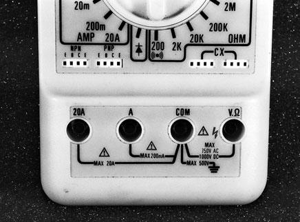
Fig. 3-14. A meter showing a 1- and 20-amp socket. The 1-amp socket would be used to measure milliamps. series with the circuit. (If you have probes on your meter leads, you’ll find this test much easier if you go out and buy a set of leads with alligator clips on the working end of the leads.) First make sure the circuit is turned off and that your meter is turned on and set up properly. Double-check to make sure that the red lead is plugged into the socket for 10 or 20 amps, if your meter has one. Now disconnect a wire at the point where you wish to measure the amperage and clip the black probe to the terminal that is closest to the battery. Clip the red probe to the remaining terminal. Figure 3-13 illustrates this basic hookup.
The meter’s leads must be in the appropriate socket for the level of amperage being read. Meters with the ability to measure both milliamps and whole amps up to the 10- or 20-amp level may have separate sockets for the red test lead as shown in figure 3-14. The black lead will remain in the “COM” socket. If your meter is self-scaling, you’ll have to select between AC and DC only. If the meter is not selfscaling, you’ll have to select a scale appropriate for your expected reading. Figure 3-15 shows some typical current values for the equipment on your boat.
Using an Inductive Pickup
If you have an inductive meter, it may have several scales to select from. Generally these meters will have a high- and a low-amps scale in addition to the usual selection of AC or DC. As with the standard meter, simply select the scale for your expected reading based on the chart in figure 3-15. Some inductive meters require the DC amperage scale to be calibrated before each use. In this case, with the meter set up and the jaws of the clamp closed, just rotate the calibration knob until zero appears on the scale.
Now isolate a wire at the point in the circuit where you want to measure amperage. This might involve unbundling a bunch of wires, or in extreme cases it might involve adding a short run of wire to a circuit. If you must add a piece of wire to get a place to clamp your meter, make sure the wire is large enough for the circuit and that the temporary terminals are tight; otherwise you might change the dynamics of the circuit enough to get an inaccurate reading. Once you have a wire isolated, simply clamp


