6 minute read
Operation

from The titleMustang ML48 All Wheel Steer Loader Operator's Manual 918134 - PDF DOWN of your publication

Operator's seat
WARNING!
Never change the seat position when driving or working –Accident risk.
☞ Adjust the seat before moving the machine.
☞ Make sure the levers for seat adjustment are safely engaged.
You can adjust the seat suspension to your weight in 9 levels, 110 – 287 lbs. (50 – 130 kg), with lever 22.
☞ Sit down on the operator’s seat. For a higher weight:
☞ Press lever 23 down 22 lbs. (10 kg) per notch. For a lower weight:
☞ Press lever 23 down to the lowest position.
➥ Weight setting automatically returns to the upper 110 lbs. (50 kg) position.
☞ Press lever 23 down to the required position.
Horizontal adjustment
☞ Sit down on the operator’s seat.
☞ Pull lever 25 up A and at the same time move the operator's seat forward or rearward B .
Backrest adjustment
☞ Sit down on the operator’s seat.
☞ Pull handle 29 up C, and at the same time move the seat forward or rearward D. The backrest reclines as follows E:
• Seat moved forward. ➥ Flatter backrest inclination.
• Seat moved rearward. ➥ Steeper backrest inclination.
Seat belt
WARNING!
Do not drive or work with the seat belt unbuckled –Risk of personal injury.
☞ Buckle up before moving or working with the machine.
•Seat belt must not be twisted.
•Seat belt must run over the hips, not over the stomach, and must always be applied tightly.
•Do not place seat belt over hard-edged, or fragile items (tools, metal ruler, glasses, pen) carried inside your clothes.
•Never buckle up two persons by using one seat belt.
•Check seat belts regularly. Have damaged parts immediately replaced by an authorized dealer.
•Always keep seat belt clean.
After an accident, the seat belt strap is stretched and is no longer serviceable. In another accident the same strap –Will not provide adequate protection.
☞ Replace the seat belt strap after an accident.
☞ Have fastening points and seat fixture checked for bearing capacity.
Seat belt 24 is designed for the operator's safety during work on construction sites and road travel.
Fastening the seat belt
☞ Fasten seat belt 24 as follows before moving the machine:
• Hold the belt at buckle latch A and run it slowly and steadily over the hips to buckle B
• Insert buckle latch A into buckle B until it engages audibly ( pull test).
• Tighten seat belt by pulling at its end.
➥The seat belt must always be tightly in place over the hips.
Unfastening the seat belt
☞ Unfasten seat belt 24 as follows:
• Hold the seat belt.
• Press red button C on buckle B
➥Latch A is released from buckle B by spring action.
• Slowly return the seat belt to the retractor.
30763b0006.eps
Lengthen/shorten seat belt setting
☞ Lengthen the seat belt as follows:
• Hold buckle latch A at a right angle to the seat belt and pull the seat belt to the required length.
☞ Shorten the seat belt by pulling the free end D of the belt.
IMPORTANT!
When pulled slowly, the automatic seat belt allows full freedom of movement. However, it locks during abrupt braking and may also lock when driving over potholes or uneven terrain.
Operation
Doors
WARNING!
Close the doors when driving and working with the machine –Accident risk.


☞ Close the doors before moving the machine.
Opening the door from the outside
☞ Pull door handle A to the outside.
Opening the door from the inside
☞ Pull lever B.
NOTE:
Normally, enter and exit the cab by using the left door. If you leave the cab on the right side, secure the control lever (joystick) and fold back the control lever base.
–see Exit on right side of cab on page74.
Securing an open door
☞ Press the door against the bracket of arrester 18 until it audibly locks.
IMPORTANT!
Lubricate latch 11 weekly.
Locking the door
☞ Press button B of latch 11
➥ The door is released from the lock.
☞ Close the door.
Opening the cab door to a gap
The door can be opened to a gap and secured with the arrester to improve cab ventilation.

☞ Safely engage lever C in door lock D.
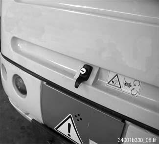
Engine cover
Opening
☞ Press lock A
☞ Pull the engine cover upwards.
Closing
☞ Firmly press down the engine cover until lock A audibly locks. Locking and unlocking Lock the engine cover with the ignition key of the ignition switch.
Operation
Other controls
Exit on right side of cab
The cab door on the right can be used as an entry and exit.
☞ Do the following before entering or exiting the cab:
• Stop and secure the machine –see Parking the machine on page61.
• Lower the loader unit.
• Apply the parking brake.
• Turn off the engine.
• Remove the ignition key.
• Move control lever 10 (joystick) back and forth several times –see Lowering the loader unit with the engine turned off on page79.

• Secure control lever 10 (joystick) –see Control lever lock (joystick) on page77.
☞ Raise control lever base 12 with handle D to position A
➥ The gas strut keeps the control lever base in the top position.
CAUTION!
DO NOT use handle D on the control lever base as a support for your entrance or exit:
☞ Use the entrance handles in the cab.
☞ Fold control lever base 12 downwards to position B after you are in the cab.

➥ The gas strut keeps the control lever base in the lower position.
NOTE:
The control lever base height can be set with stop bolt C
Removing the cab for low clearance heights
Machine height without cab –see Dimensions model ML48 on page142
WARNING!
Incorrectly removing the cab with a crane –Accident risk.
☞ Have loads fastened.
☞ Make sure the lifting capacities of the crane and the lifting gear (cables, chains) are sufficient.
☞ Avoid suspended loads.
☞ Always read the safety instructions
–see Safety instructions on page15.
☞ Remove the cab as follows:
• Drive the machine onto level ground.
• Turn off the engine.
• Remove the ignition key.
• Lower the loader unit without pressure
–see Lowering the loader unit with the engine turned off on page79.
• Remove electrical connection A (behind the operator's seat, on the left).
• Remove the rear left and right mudguards.
• Remove the left and right hexagon head screws B used for securing the cab.

• Carefully raise the cab at the four eye hooks C by using a crane.
• Place the cab onto level ground.
Mounting the cab
☞ Mount the cab in the reverse order of removal. Tightening torque for cab attachment: 144 lb.-ft. (195 Nm).

Operation
Working with the machine
General safety instructions
• Never drive up to the edge of a pit from the outside – risk of cave-in.
• Never undermine the foundations of walls – risk of collapse.
• When excavating, look out for high-voltage and underground cables, and gas and water pipes.
• When using lifting accessories such as pallet forks, comply with the load diagrams –see Load diagram on page94.
• The hydraulic system of the machine is still pressurized even when the engine is not running. Depressurize the sections of the s ystem and hydraulic lines that you want to open before starting setup or repair work (e.g., fitting/removing an attachment with hydraulic functions) –see Depressurizing the quick couplers on the loader unit on page79
• If your machine is equipped with a load stabilizer (option):
IMPORTANT!
Turn off the load stabilizer before working with the loader unit. If you leave the load stabilizer on, the lifting capacity of the machine is only about 60% of the rated force.
Handleverofthemachine
Control lever for lift and tilt cylinder hydraulics
WARNING!
Unintentional operation of control lever 10 when driving on public roads: Accident risk.
☞ Lock the lock lever 80/16 –see Control lever lock (joystick) on page77.
Position Lever 10 Function
• A ☞ Left ➥ Tilts in attachment
• B ☞ Right ➥ Dumps out attachment
• C ☞ Forward ➥ Lowers boom
• D ☞ Rearward ➥ Raises boom
• E ☞ Fully forward ➥ Lowers boom to float position
NOTE:
The control valve is equipped with a float position. This helps you when working with a rotary broom, snowplow, and grading in reverse.
Complete the following procedures to turn on the float position:
☞ Push control lever 10 fully forward to final position E.
Control lever lock (joystick)
The lock lever for locking the control lever is located on the control lever base console.
Locking the lock lever
☞ Push lock lever 16 lever forward A.
➥ The control valve is cut off from the hydraulic oil circuit.
➥ Follow these instructions
–see Before driving the machine on page48.
Opening the lock lever
☞ Push stop cock 16 lever rearward B.
➥ The control valve is connected to the hydraulic oil circuit.