22 minute read
Chapter 6


Operation And Adjustments
General Information
Caution
BEFORE starting the engine and operating the Telehandler, review and comply with ALL safety recommendations in the Safety chapter of this manual. Know how to STOP the machine before starting it. Also, BE SURE to fasten and properly adjust the seatbelt.
ENGINE BREAK-IN
A new engine does not require extensive “break-in.” However, for the first 100 hours of operation, follow these guidelines: Allow the engine to idle for a few minutes after every cold start. DO NOT idle the engine for long periods of time. DO NOT operate the engine at maximum power for long periods of time. Check the oil level frequently and replenish as necessary with the oil specified in the engine manual.
Yanmar engines do not use a “break-in” oil. After the first 50 hours of operation, change the oil and replace the oil filter. Consult the Lubrication chapter for the type and grade of oil to use. Refer to the Service and Storage chapter for the proper service intervals.
PRE-START INSPECTION
It is the operator’s responsibility to inspect the machine before the start of each workday. Every pre-start inspection must include more than checking the fuel and oil levels. It is a good practice to personally inspect any machine you are assigned to use, even though it has already been put into service by other personnel.
The most efficient method of checking a machine is by conducting a “Walk-Around Inspection.”
The following items should be included in the “WalkAround Inspection:”
1.Attachment Tool: Check for broken missing or damaged parts. When utilizing forks, check for welds, cracks or misalignment. Replace the forks in sets when the condition of the fork(s) is questionable.
IMPORTANT: DO NOT use forks that have been repaired by welding.
2.Attachment Tool Mount: No loose or missing parts; no visible damage. Lock pins/plate in the locked position.
3.Attachment Tool Mounting Pins: No visible damage; pin fit is secure and properly lubricated.
4.Boom Section and Wear Pads: No loose or missing parts; no visible damage; no excessive wear.
NOTE: Wear pads that measure 3/8” (9.5 mm) thick or less need to be replaced.
5.Boom Angle Indicator: Looseness; no visible damage; bubble is visible.
6.Tire and Wheel Assemblies: Properly secured; no loose or missing lug nuts; no visible damage (cuts or abrasions); proper tire inflation.
7.Tie Rod Linkage and Steering Knuckles: No loose or missing parts; no visible damage; tie rod end studs locked; properly lubricated.
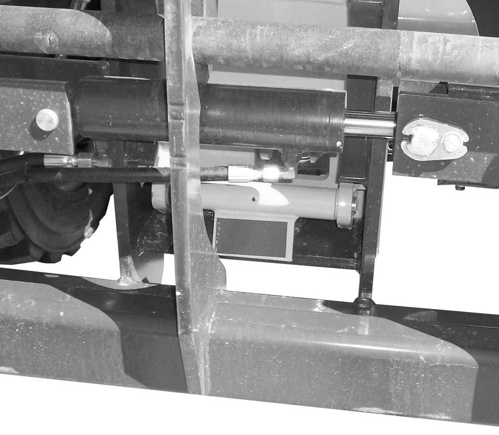
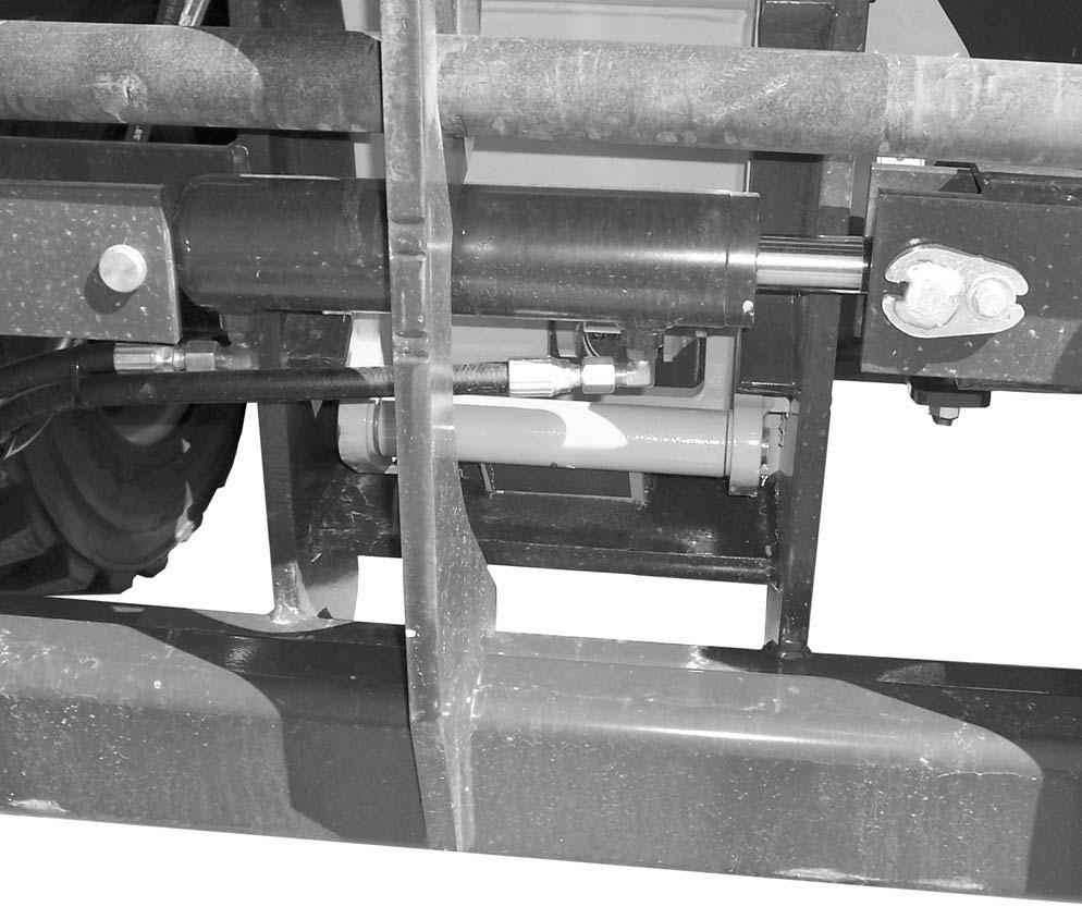
8.Lift Cylinder: Properly secured; no visible damage; no evidence of leaking from the cylinder; properly lubricated.
9.Slave Cylinder: Properly secured; no visible damage; no evidence of leaking from the cylinder; properly lubricated.
10.Boom Pivot Assembly: Properly secured; no visible damage or excessive wear; properly lubricated.
11.Boom Hydraulic Hoses: No visible damage or exterior wear; no evidence of leaking.
12.Rear Light Assemblies (when equipped): Properly secured; no visible damage; no loose or disconnected wires; function properly.
13.Hydraulic Control Valve Assembly: No loose or missing parts; not leaking; no damaged or leaking hoses.
14.Covers, Doors and Latches: All covers doors and latches are in working condition; properly secured with no loose or missing parts; all components operate properly.
15.Exhaust System: No loose or missing parts; no visible damage; no obstructions to the outlet.
16.Hydraulic Cooler and Radiator: No loose or missing parts; no visible damage; no evidence of leaking; cleanliness.
17.Hydraulic Oil Reservoir: No evidence of leaking; breather cap working and secure.
18.Engine Oil Reservoir: No evidence of leaking; dipstick fits securely.
19.Battery Compartment: No loose or broken cables; no damage or corrosion.
20.Fuel Tank: No damage or leaking; breather cap secure and working.
21.Engine Air Cleaner: No loose or missing parts; no obstructions to the inlet.
22.Mirror Assembly: No visible damage; adjusted properly.
23.Attachment Tilt Cylinder: Properly secured; no visible damage; no evidence of leaking from the cylinder; properly lubricated.
24.Frame: No cracks or visible damage.
25.Tilt and Auxiliary Hydraulic Hoses: No damage or excessive wear; no evidence of leaking.
26.Frame Angle Indicator: Looseness; no visible damage; bubble is visible.
27.Operator Control Console: Switches and levers undamaged; no loose or missing parts; load charts properly secured and legible; levers and switches operate properly; control decals are legible.
Along with performing the “Walk-Around Inspection”, the operator should perform the “10 Hour or Daily Service Checks” found in the Service and Storage chapter.
Before mounting the operator’s compartment, walk completely around the machine to be sure no one is under, on, or close to it. Let others in the area know you are going to start up and wait until everyone is clear of the machine.
Before Starting Engine
Before starting the engine and running the machine, refer to the Indicators and Controls chapter and become familiar with the various operating controls, indicators and safety features.
Starting The Engine
The following procedure is recommended for starting the engine:
1.Grasp the hand holds to step up into the operator’s compartment.
2.Adjust the seat and fasten the seat belt.
Warning
ALWAYS fasten your seat belt before starting the engine. Leave the parking brake applied until the engine is running and you are ready to operate the machine.
3.Check that all controls are in their “neutral” positions, except the parking brake switch, which should be in the “ON” position.
Warning
Do not use starting fluid (ether) with engine preheat systems. An explosion can result, which can cause engine damage, injury or death.
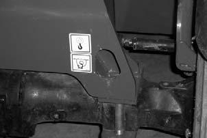
4.Turn the key switch to “ON” position. The preheat indicator on the multi-function display will be “ON” indicating the pre-heater is in use. When the indicator goes out, the engine can be started. NOTE: The engine pre-heater is used to assist starting in cold weather conditions. The indicator may stay lighted for 3-30 seconds depending on the temperature. If you are operating the telehandler in normal or warm weather conditions, the pre-heat indicator will go out in several seconds and you can start the engine.
5.Press the start button. Release the button as soon as the engine starts. If the button is released before the engine starts, turn the keyswitch to “OFF” position and allow the starter to stop before attempting to start again.
IMPORTANT: Crank the starter until the engine starts. If the engine fails to start within 15 seconds, return the key to the “OFF” position, wait at least 30 seconds, and try again to start the engine. Cranking the engine for longer than 15 seconds will result in premature failure of the starter.
6.After the engine starts, allow a sufficient warm-up time before operating the controls.
7.Check that indicators are in normal condition.
8.Check that there are no fuel, oil or engine coolant leaks, and no abnormal noises or vibrations.
Cold Starting
A optional block heater is recommended for starting in temperatures of 20oF (-7oC) or lower.
The block heater should be connected to an AC power supply several hours prior to starting the engine depending on the ambient temperature.
Warning
Do not use starting fluid (ether) with engine preheat systems. An explosion can result, which can cause engine damage, injury or death.
If the battery becomes discharged and does not have sufficient power to start the engine, jumper cables can be used for starting assistance. Refer to the jump starting instructions in the Service and Storage chapter of this manual for safe jump starting procedures.
Stopping
The following procedure is the recommended sequence for stopping the machine:
1.Bring the machine to a stop on a level surface. Avoid parking on a slope, but if necessary, park across the slope and block the tires.
2.Fully retract the boom and lower the attachment to the ground. Idle the engine for gradual cooling.
3.Place controls in neutral. Apply the parking brake.
4.Turn the ignition switch key to the “OFF” position. Remove the key.
5.Unfasten the seatbelt, and grasp the hand holds while climbing out of the operator’s compartment.
First Time Operation
Caution
Be sure the area used for test-running is clear of spectators and obstructions. Initially, operate the machine with an empty attachment tool.
Make sure the engine is warm and then go through the following procedures:
Select the travel direction. Switch off the parking brake and move ahead slowly, while testing the steering and brakes. Stop and operate all boom and attachment tool function controls, checking for smooth response.
Apply the service brakes, stop the machine and move the travel lever to the opposite direction.
IMPORTANT: To prevent damage to the transmission, the Telehandler should be traveling at a slow speed and not accelerating when changing the direction of travel.
Parking Brake
NOTE: The parking brake mechanism within the front axle is NOT designed for, OR intended to be used as, the primary means of stopping movement of the machine. Hydraulic braking provided through the service brakes within the axles is the primary means for stopping movement. The axleby-axle split brake system is the secondary means of stopping movement.
The proper sequence for correct machine operation is to always engage the parking brake switch before shutting off the engine; and to disengage the parking brake ONLY after the engine is running. In an EMERGENCY, if it becomes necessary to stop the machine, activate the parking brake switch to “ON.”
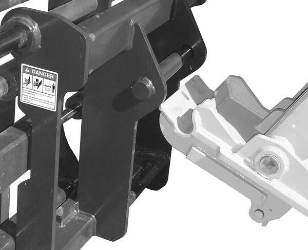
Changing Attachment Tools
The Telehandler boom nose will accept Mustang Quick-attach System attachment tools. The Quickattach System has a quick-release hookup and locking mechanism for mounting framing-type or masonrytype attachment tools to the boom nose.
Attaching
To pick up the attachment tool, proceed as follows:
1.Raise the boom slightly, extend it 2 to 3 feet (600900 mm) for better visibility, and tilt the Quickattach System forward.
2.Align the Quick-attach System squarely with the back of the attachment tool.
3.Slowly extend the Quick-attach System and lower the hooks under the attachment tool hookup bar.
4.Tilt the Quick-attach System back so that the lock plate engages the attachment tool. This secures the attachment tool to the Quick-attach System.
5.For an attachment tool with auxiliary hydraulics, connect hoses to the quick-disconnect connectors on the boom nose.
4.Tilt the Quick-attach System forward to allow the attachment tool to roll out, then lower the boom so the hook ears clear the hookup bar on the attachment tool.
NOTE: One side of the lock plate has a bright red decal to indicate the unlocked position.
5.If the attachment tool has auxiliary hydraulics, disconnect the hoses from the quick-disconnects on the boom nose.
6.Start the engine and tilt the Quick-attach System forward, then slowly back the machine until the attachment tool is free from the boom nose.
Warning
Detaching
To detach attachment tool, proceed as follows:
1.Raise the boom slightly and extend it 2 to 3 feet (600-900 mm) for better visibility. Lower the boom until the attachment tool is approximately 12” (300 mm) off the ground.
2.Roll the carrier rearward as far as it will go. When the carrier is rolled all the way back, perform the Mandatory Safety Shutdown Procedure (p. 8, Safety chapter).
3.With the engine off, leave the operator’s station. Manually raise the lock spring, and flip the lock plate up and outward at least 180o so it is in position to re-lock on the next attachment tool.
Modifications, alterations to, or use of attachment tools not authorized by Mustang (or the manufacturer) in writing can void warranty and cause machine damage and/or serious personal injury or death.
SELF-LEVELING
The machine is equipped with a hydraulic self-leveling feature. This feature is designed to keep the attachment tool level while the boom is being raised and lowered.
General Machine Operation
Check the Telehandler to be sure all systems are in good operating condition. Perform the following steps before starting the machine the first time each day:
1.Check the engine oil, coolant and hydraulic oil levels.
2.Check hydraulic oil cooler and engine radiator for debris.
3.Be sure weekly lubrication has been done.
4.Visually inspect for leaks and broken or malfunctioning parts. Be sure all caps, covers and safety shields are in place.
5.Check tires for cuts, bulges, nails, correct pressure, loose wheel nuts, etc.
6.Inspect the work area. Be sure you know where you will make load pickups, lifts and turns. Look over the terrain of the jobsite for holes, obstacles, slippery surfaces, and soft or deep mud.
7.Check clearances of ramps, doorways and passage-ways. Check overhead clearances if you will travel and place loads near power or telephone lines.
Warning
Exhaust fumes can kill. Ensure proper ventilation when starting indoors or in enclosed areas.
Use proper hand holds, NOT the steering wheel or control levers when mounting and dismounting.
NEVER operate the machine with safety guards or covers removed.
Over-inflated tires can explode and cause injury or death. Tire repairs MUST be made only by authorized personnel using proper tools and equipment.
If the machine is in need of repair or in any way unsafe, or contributes to an unsafe condition, the matter must be reported immediately to the user’s designated authority. The machine must NOT be operated until it has been restored to a safe operating condition.
Operate the travel controls gradually and smoothly when starting, stopping, turning and reversing direction.
Grade and Slope Precautions
The Telehandler complies with industry stability test requirements and is stable when properly operated. However, improper operation, faulty maintenance, and poor housekeeping can contribute to a condition of instability and defeat the purpose of the standard.
The amount of forward and rearward tilt to be used is governed by the application. Although use of maximum rearward tilt is allowable under certain conditions, such as traveling with the load fully lowered, the stability limits of the machine, as determined by the industry standard tests, do not encompass consideration for excessive tilt at high elevations, or the handling of off-center loads.
Only handle loads within the capacity limits of the machine, and which are stable and safely arranged. When attachments are used, extra care should be taken in securing, manipulating, positioning and transporting the load.
Grade Limits
NOTE: Grade limits are based on ANSI/ITSDF standard B56.6-2005.
This Telehandler meets or exceeds the safety standard (ANSI/ITSDF B56.6) stability limits for rough terrain forklifts. The stability tipping limits cover specific, controlled test conditions, which are extremes, and which are not intended to be achieved during normal worksite operations. The following specifications are provided only as information to the operator, and must not be used as a guideline for operating the Telehandler. For safe operation, always follow the instructions and warnings provided in this manual.
1.DO NOT place or retrieve loads on an up or down slope or grade that exceeds 7% or 4°.
2.DO NOT travel up or down a grade or slope that exceeds 22% or 12° while loaded.
3.DO NOT place or retrieve loads on a side hill with a slope or grade that exceeds 12% or 7°. Check the location of the ball in the frame angle indicator located on the ROPS/FOPS cross member. If the ball in the frame angle indicator is in the green zone, it is safe to place or retrieve the load. If the ball in the frame angle indicator is in the yellow zone, use slower movements and extra caution to ensure remaining within the limits of the load chart, because the machine is nearing an unstable condition. If the ball in the frame angle indicator is in the red zone, loads cannot be placed or retrieved.
4.DO NOT travel across a side hill that exceeds 18% or 10° grade. Check the frame angle indicator on the ROPS/FOPS cross member to determine the angle of the grade. The attachment tool MUST be maintained at the “carry” position, with the boom fully retracted and attachment tool at minimum ground clearance.
When ascending or descending grades in excess of 5% or 3°, the machine should be driven with the load upgrade. An unloaded machine should be operated on all grades with the load handling attachment tool downgrade, tilted back if applicable, and raised only as far as necessary to clear the ground surface.
Avoid turning if possible and use extreme caution on grades, ramps and inclines. Normally travel straight up and down the slope.
Traffic Flow Patterns
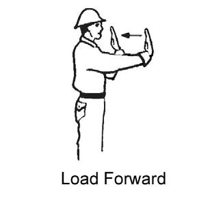
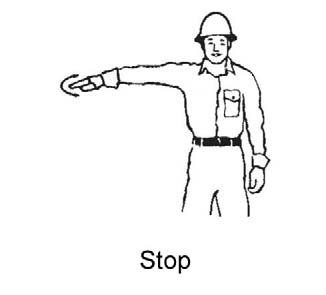
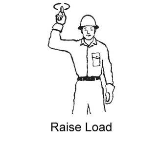
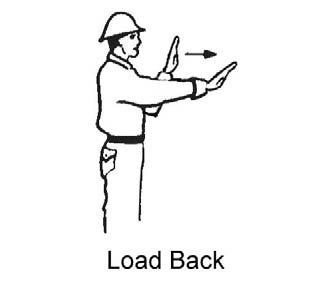
Know and understand the traffic flow patterns of your jobsite. Know all Telehandler hand signals for safety. Use signal persons as necessary for safe operation, and be sure you can see the signal person and acknowledge the signals given.

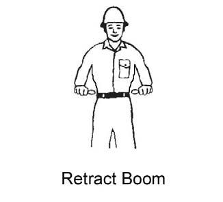


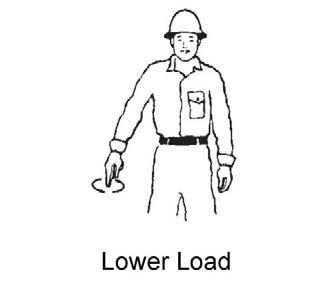
Safety Hand Signals

When ramps must be used in transporting loads with the machine, the following are the minimum widths for safe travel:
Compacted dirt, gravel, etc.12 ft. (3.6 m)
Woodboard, concrete, etc.10 ft. (3.0 m)
Permanent aisles, roadways and passageways, floors and ramps must be clearly defined or marked. Permanent or temporary protrusion of loads, equipment, material and construction facilities into the usual operating area must be guarded, clearly and distinctively marked, or clearly visible.
Maintain a safe distance from the edge of ramps, platforms and other similar working surfaces.
Controlled lighting of adequate intensity should be provided in operating areas. Where operating conditions indicate, the operator/user is responsible for having the machine equipped with lights.
Provisions must be made to prevent trucks, semi-trailers and railroad cars from being moved during loading and unloading.
Wheel stops, parking brakes, or other positive holding means must be used to prevent movement during loading and unloading.
DO NOT move railroad cars and trailers with the Telehandler.
DO NOT use the boom and attachment for leverage to push the machine out of mud.
IMPORTANT: DO NOT lower boom at high engine speed when attachment tool is at maximum rearward tilt, because damage to slave cylinders may result.
General Load Handling
NEVER attempt to work controls except from the operator’s seat. NEVER jerk or use fast movements. Avoid sudden stops, starts and changes in direction. Operation of the hydraulic system depends on engine speed and the distance the controls are moved. When operating these controls it is important to develop a technique called “feathering.” Feathering the control means starting the desired motion by moving the control a small amount away from neutral. Then after movement has started, the control can be eased to full movement. Use the same feathering technique to stop the motion.
Warning
Excessive speed can be hazardous. ALWAYS exercise caution and good judgement while operating the machine.
ALWAYS maintain a safe distance from electric power lines and avoid contact with any electrically charged conductor and gas line. It is not necessary to make direct contact with a power line for power to ground through the structure of the machine. Keep the boom and load at least 10 ft. (3 m) from all power lines. Accidental contact or rupture can result in electrocution or an explosion. Contact the North American One-Call Referral System at (888) 258-0808 for the local “Digger’s Hotline” number or proper local authorities for utility line locations BEFORE starting to dig!
Keep all body parts inside the operator’s station while operating the machine. BE SURE of clearance for the attachment tool when turning, working around buildings, etc.
Turning corners too fast can tip the machine, or cause a load to tip off the attachment. Sudden slowing or stopping of the machine may cause the load to drop off the attachment tool.
Be certain you can control both speed and direction before moving. Always place the machine in neutral and set the parking brake before raising or extending the boom. NEVER drive the machine up to someone standing in front of the load.
NEVER leave the operator’s station without first lowering the attachment tool to the ground. Then set the parking brake, place controls in neutral, shut off engine and remove the key. AVOID parking the machine on a slope, but if necessary, park across the slope and block the tires.
Load Capacity and Reach
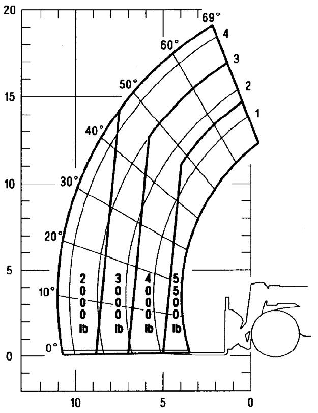
This machine has flip-charts in the operator’s station that provide the load capacity limits at various positions of attachment tool extension and elevation. A set of the load zone charts is reproduced at the end of this manual for reference.
A typical load zone chart is shown on the next page. The scale on the left indicates height in feet above the ground level. The scale on the bottom shows the distance in feet out from the front of the machine. The arc lines noted by the numbers “1” through “4” correspond to the position extension markers on the operator side of the inner boom section.
The following example illustrates proper use of the load zone charts for the Telehandler:
Warning
NEVER exceed the rated operating capacity of the Telehandler as shown on the load zone charts.
Example:
The operator, using a standard carriage attachment tool, wants to raise a 4000 pound load 10 feet high, and can only get to within 5 feet of the load placement point. Can it be done within the capacity of the machine?
Analysis: See “Typical Load Zone Chart” below.
Projecting up from the 5-foot mark on the horizontal axis to intersect a line through the 10-foot mark on the vertical axis shows the load can be placed in the 4000 pound zone.
During placement, the operator observes when the extension reference number “2” on the boom becomes visible and stops. The maximum safe distance of extension with this load has been reached.
Warning
Operating conditions can reduce the machine’s safe operating capacity. Exceeding the capacity when raising or extending the boom will cause the machine to tip forward.
Approach the load squarely and slowly with the machine straight and level. Adjust the space between forks, if necessary. Engage the load equally on both forks until the load touches the carriage backrest. Tilt the forks back to position the load for travel.
Carrying the Load
If the load obstructs your view, get someone to direct you. Maintain ground speeds consistent with ground conditions and which permit stopping in a safe manner.
Warning
NEVER travel with the boom above the carry position (attachment tool should be at minimum ground clearance). Boom should be fully retracted.
NEVER coast with the transmission in neutral. Travel up and down grades slowly.
DO NOT operate the machine on a slope or grade that exceeds 22% or 12o.
Elevating and Placing the Load
DISTANCE LOAD IS EXTENDED
Typical Load Zone Chart
Lifting Attachment Tool Applications
Picking Up the Load
Inspect the load. If it appears unstable, DO NOT attempt to move it. DO NOT attempt lifting doubletiered loads, or straddling side-by-side pallets with one on each fork. NEVER add extra unauthorized counterweights to this machine.
For ground level load placement, be sure the area under the load and around the machine is clear of equipment and personnel. Lower the load to the ground, tilt the forks to the horizontal position, and then carefully back away to disengage forks from the load.
For elevated or overhead placement, bring the machine as close as possible to the landing point, and then:
Warning
DO NOT raise the boom until you check the frame angle indicator to verify that the ball is in a safe zone for raising and placing a high load.
1.Use extreme caution for high placement. Be sure personnel are clear of the area where the load or the machine could tip or fall.
Warning
Be sure that the surrounding ground has adequate strength to support the weight of the machine and the load it is carrying.
Always wear the seat belt provided to prevent being thrown from the machine. If you are in an overturn:
- DO NOT jump!
- Hold on tight and stay with the machine!
- Lean away from the fall!
2.Set the parking brake, hold the service brake pedal in fully applied position and slowly raise the load, maintaining a slight rearward tilt to cradle the load.
3.As the load approaches the desired height, feather the boom control at minimum speed until the load is slightly higher than the landing point.
4.Continue the feathering technique and lower the load into place.
5.Free the forks from the load by alternately retracting and raising the boom. If this process is not possible, very slowly and carefully reverse the telehandler to free the forks from the load.
6.Lower the forks to travel height.
Warning
The machine becomes less stable as the load is raised higher.
Before raising a load, be sure the Telehandler is within the safe lifting parameter as indicated by the frame angle indicator.
If a hydraulic boom circuit hose should break with the boom up, shut down the machine. DO NOT attempt to bring down the boom or make repairs. Call your Mustang dealer immediately.
As lift height increases, depth perception decreases. High elevation placement may require a signal person to guide the operator.
DO NOT ram the lift cylinder to the end of the stroke. The resulting jolt could spill the load.
A jib or truss boom should ONLY be used to lift and place loads when the machine is stationary and the frame is level. Transporting suspended loads must ALWAYS be done slowly and cautiously, with the boom and load as low as possible. Use taglines to restrict loads from swinging, to avoid overturns.
Suspended Loads
The handling of suspended loads by means of a truss boom or other similar device can introduce dynamic forces affecting the stability of the machine that are not considered in the stability criteria of industry test standards. Grades and sudden starts, stops and turns can cause the load to swing and create a hazard.
Guidelines for “Free Rigging / Suspended Loads”
1.DO NOT exceed the rated capacity of the telehandler as equipped for handling suspended loads. The weight of the rigging must be included as part of the load.
2.During transport, the length of the rigging between the attachment and load should be as short as possible to reduce booms height and movement. DO NOT raise the load more than 12 inches (305 mm) above the ground, or raise the boom more than 45 degrees.
3.Only lift the load vertically – NEVER drag it horizontally.
4.Use multiple pickup points on the load when possible. Use taglines to restrain the load from swinging and rotating.
5.Start, travel, turn and stop SLOWLY to prevent the load from swinging. DO NOT exceed walking speed.
6.Inspect rigging before use. Rigging must be in good condition and in the U.S. comply with OSHA regulation §1910.184, “Slings,” or §1926.251, “Rigging equipment for material handling.”
7.Rigging equipment attached to the forks must be secured such that it cannot move either sideways or fore and aft. The load center must not exceed 24 inches (610 mm).
8.DO NOT lift the load with anyone on the load, rigging or lift equipment, and NEVER lift the load over personnel.
9.Beware of the wind, which can cause suspended loads to swing, even with taglines.
10.DO NOT attempt to use frame-leveling to compensate for load swing.
Road Travel
For short distance highway travel, attach a SlowMoving Vehicle (SMV) emblem (purchased locally) to the rear of the Telehandler. For highway operation, obtain and install an amber flashing beacon.
NOTE: ALWAYS follow ALL state and local regulations regarding the operation of equipment on or across public highways. Whenever there is an appreciable distance between jobsites, or if driving on public highway is prohibited, transport the machine using a vehicle of appropriate size and capacity.
Transporting Between Jobsites
ALWAYS abide by the following recommended procedures and guidelines when using ramps to load the machine onto (and unload it from) a truck or trailer. Failure to heed can result in damage to equipment and serious personal injury or death!
Tie-down points are provided for inserting chains to secure the machine during transport.
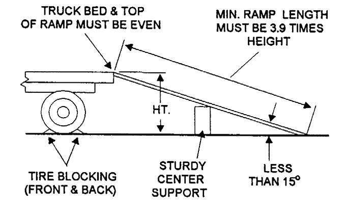
3.Incline of ramps MUST be less than 15 degrees. Ramp length MUST be at least 16 feet (4.9 m) long.
4.Ramp width MUST be at least 1-1/2 times the tire width.
5.Block the front and rear of the tires on the truck or trailer; engage the parking brake.
6.Position the machine with the boom facing toward the front of the truck or trailer so that it is straight in line with the ramps. Slowly (at the lowest engine speed possible) and carefully drive the machine up the ramps.
7.Tie-down points are provided at the front and rear corners of the frame structure.
Warning
NEVER adjust travel direction (even slightly) while on the ramps. Instead, back off the ramps, and then realign the machine with the ramps.
Warning
Loading Machine Using Ramps
NOTE: A matched pair of ramps is required.
1.The ramps MUST be of sufficient strength to support the machine. Whenever possible, the use of strong steel ramps is recommended as well as center supporting blocks.
2.The ramps MUST be firmly attached to the truck or trailer bed with NO step between the bed and the ramps.
NEVER transport the machine with the boom raised or extended. BE SURE to secure the machine (including boom) to the truck or trailer bed using chain and binders or steel cables, to prevent any movement while transporting.
Unloading Machine Using Ramps
NOTE: A matched pair of ramps is required.
Repeat Steps 1 through 5 and proceed as follows to unload the machine:
6.Remove the tie-down chains/cables.
7.If necessary, adjust the machine so that the wheels are in line and centered with the ramps.
8.Slowly (at the lowest engine speed possible) and carefully drive the machine down the ramps.
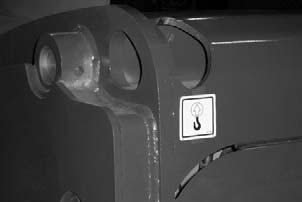
Lifting The Telehandler
Towing The Telehandler
Warning
Do not tow the Telehandler at more than 3 mph (5 km/h), and only for short distances (less than 100 yards).
If the machine becomes disabled, it can be towed for a short distance. To tow the Telehandler, the high pressure limiters on the hydrostatic transmission must be unlocked and the SAHR parking brake must be released.
The Telehandler can be lifted using the four lifting points shown above.
Lift equipment used and its installation is the responsibility of the party conducting the lift. All rigging must comply with applicable regulations and guidelines.
Warning
Before lifting, check the lifting equipment for proper installation.
-Never allow riders in the operator’s station while the telehandler is lifted.
-Keep everyone a safe distance away from the telehandler while it is lifted.
-The telehandler may only be lifted without a load on the forks, or without an attachment. Never lift the telehandler with attachment other than those stated.
1.Using suitable lift equipment, hook into the lift eyes. Adjust the length of the slings or chains to lift the telehandler level.
IMPORTANT: As needed, use a spreader bar to prevent the slings or chains from rubbing the sides of the boom.
2.Center the hoist over the Telehandler. To prevent shock loading of the equipment and excessive swinging of the load, slowly lift the Telehandler off the ground. Perform all movements slowly and gradually. As needed, use a tag line to help position the Telehandler.
Hydrostatic Transmission Unlocking Procedure
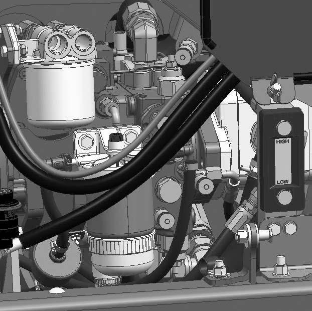
1.Remove the plastic caps on the high pressure limiters.
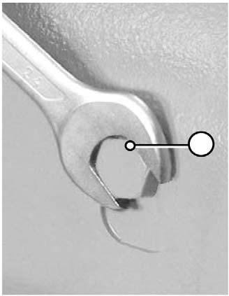
3.While holding the jam nut, use an Allen wrench to turn the center release screw in until it bottoms.
4.Tighten the jam nut.
5.Repeat steps 2-4 for the other high pressure limiter.
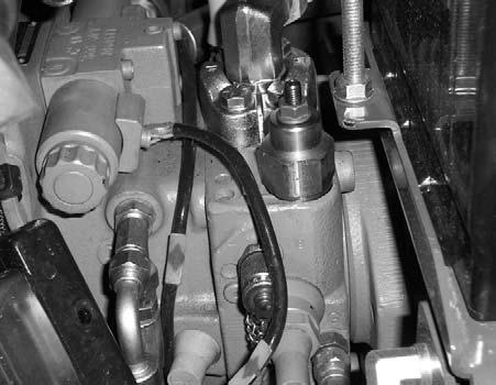
SAHR Parking Brake Releasing Procedure
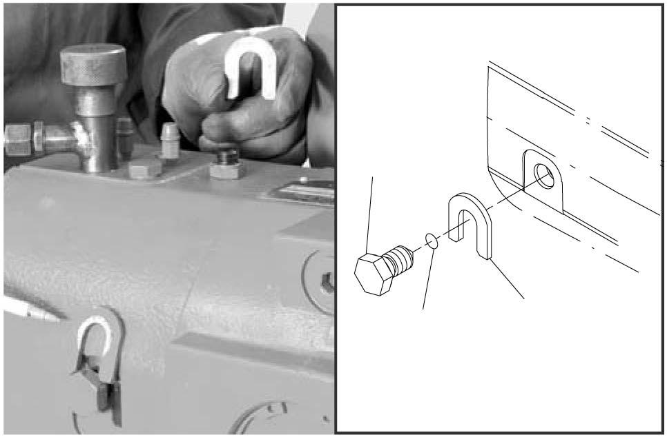
1.There are unlocking screws on the front and rear sides of the axle. Locate and loosen both unlocking screws (1) and remove the stop washers (3).
SAHR Parking Brake Applying Procedure
1.Loosen the unlocking screws (1) and re-install the stop washers (3).
2.Tighten the unlocking screws against the stop washers.
Hydrostatic Transmission Locking Procedure
1.Loosen the jam nut on a high pressure limiter.
2.Using an Allen wrench, turn the center release screw back out until it stops.
3.Tighten the jam nut.
4.Repeat steps 1-3 for the other high pressure limiter.
Theft Deterrents
Mustang has recorded all major component part numbers and serial numbers. Users should take as many of the following actions as possible to discourage theft, to aid in the recovery in the event the machine is stolen, and to reduce vandalism:
1.Remove keys from unattended machines.
2.Attach, secure, and lock all anti-vandalism and anti-theft devices on the machine.
3.Lock doors of cabs when not in use.
4.Inspect the gates and fences of the equipment storage yard. If possible, keep machines in well-lighted areas. Ask the local law enforcement agency to make frequent checks around the storage and work sites, especially at night, during weekends, and on holidays.
5.Report any theft to your dealer and insurance company. Provide the model and all serial numbers. Request your dealer to forward this information to Mustang Manufacturing Company.
Warning
Before the Telehandler can be returned to service, the SAHR parking brake must be returned to the applied position, and the hydrostatic transmission high pressure limiters must be locked.