13 minute read
SAFETY


Chapter 5
And Controls
Guards And Shields
Caution
Before operating the Telehandler, become familiar with and know how to use ALL safety devices and controls. Know how to stop the machine operation before operating it. This Mustang machine is designed and intended to be used ONLY with a Mustang Manufacturing Company attachment tool, or a Mustang approved accessory or referral attachment tool. Mustang Manufacturing Company cannot be responsible for safety if the machine is used with an unapproved accessory or attachment tool.
Whenever possible and without affecting machine operation, guards and shields are used to protect potentially hazardous areas. In many places, decals are also provided to warn of potential hazards and to display special operating procedures.
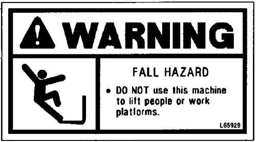
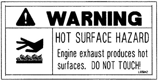
Warning
Read and thoroughly understand all safety decals on the Telehandler before operating it. DO NOT operate the machine unless all factory-installed guards and shields are properly secured in place.
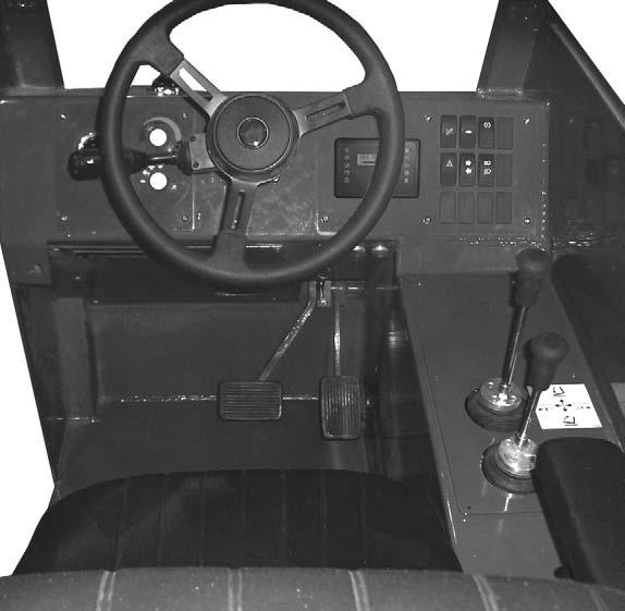
Dash Panel Area
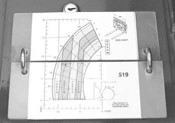
Load Zone Charts: A set of flip charts show lift height and reach limits relative to the load weight being handled with various attachment tools.
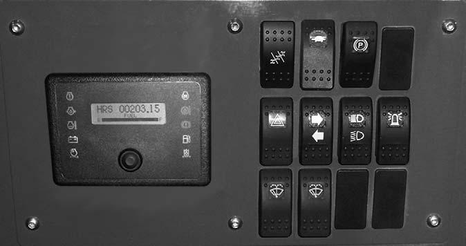
Instrument And Switch Panel
Located to the right of the steering wheel, this panel contains the instrument gauges, indicator lamps and function switches.
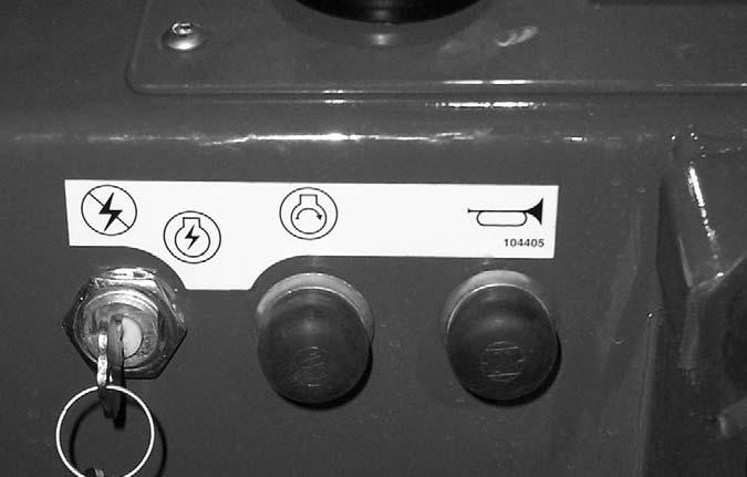
Key Switch, Start and Horn Buttons
A - Key switch OFF: When the key is vertical in the keyswitch, power is disconnected from the battery to the control and instrument panel electrical circuits. Also, this is the only position in which the key can be inserted or removed.
B - Key switch ON: When the key is turned one position clockwise from the vertical (OFF) position, power from the battery is supplied to all controls and multifunction display panel electrical circuits. Indicators on the multi-function display should light up momentarily.
When the key is in this position, the engine pre-heat indicator will stay on until the engine is pre-heated. In colder temperatures the pre-heat indicator will stay lit for 3-30 seconds. When the pre-heat indicator light goes out the engine can be started.
C - Start Button: With keyswitch in ON position, press the button to activate the starter. Release it as soon as the engine starts.
NOTE: If the engine requires repeated attempts to start, the key MUST be returned to the OFF position between starting attempts to prevent battery run down.
IMPORTANT: Do not use additional starting aids such as ether injection when using the electrical engine preheat.
D - Horn Button: With the keyswitch ON, press the horn button to activate warning sound.
Instrumentation
A - Multi-Function Display Screen: This screen displays the following functions:
• fuel level at all times,
• engine coolant temperature,
• engine speed,
• voltmeter
• hourmeter
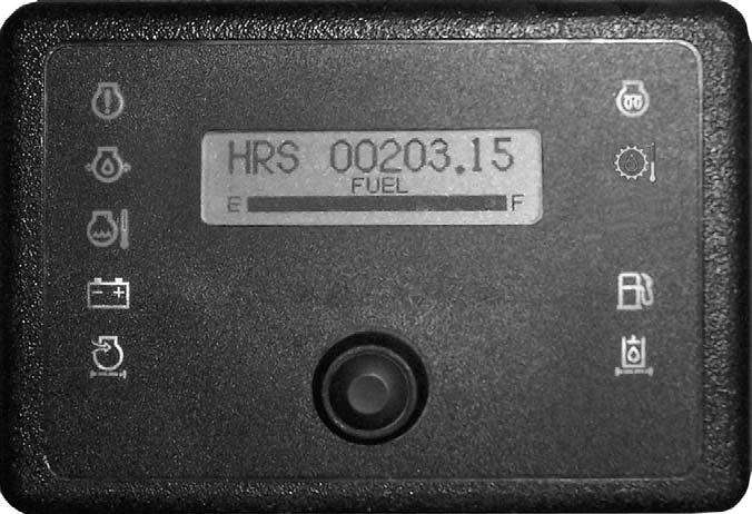
• 250 hour maintenance reminder
• error fault codes
B - Scroll Button: Pressing this button changes the function displayed in the multi-function display screen.
A1 - Fuel Level Gauge: The fuel level is displayed at all times in the lower portion of the display. It indicates the amount of fuel remaining in the fuel tank.
A2 - Engine Coolant Temperature: Press button “B” until “TEMP” is displayed. It indicates the temperature of the engine coolant. Under normal conditions, this should indicate approximately 185°F (85°C).
A3 - Engine Speed: Press button “B” until “RPM” is displayed. This indicates the engine speed.
A4 - Voltmeter: Press button “B” until “VOLTS” is displayed. This indicates the voltage output from the alternator.
A5 - Hourmeter: Press button “B” until “HRS” is displayed. It indicates the total operating time of the machine and should be used for keeping the maintenance log.
A6 - Maintenance Reminder: After every 250 hours a reminder will display: “ROUTINE MAINTENACE IS REQUIRED ⎯ CHECK OPERATOR’S MANUAL.” Perform the required maintenance, and then clear the message by pressing and holding button “B” until the message is cleared.
NOTE: The maintenance reminder message must display at least three minutes before it can be cleared by pressing and holding button “B”.
A7 - Error Fault Code: Error codes and a short error description are displayed in this screen. The error code will clear when the error is corrected.
Indicator Lamps
C - Engine Failure: This lamp when lit, alerts the operator of a fault condition. Refer to the multi-function display screen for error codes.
D - Engine Oil Pressure Lamp: This lamp indicates when the engine lubricating oil pressure is too low. During normal operation, with the engine running, this lamp should be off. During starting and when the ignition is on but the engine is not running, this lamp will be on.
IMPORTANT: If this lamp comes on during normal operation, stop the engine immediately! After allowing the oil to drain down for a few minutes, check the engine oil level. Maintain oil level at the FULL mark on the dipstick.
E - Engine Coolant Temperature Lamp: This lamp indicates when the temperature of the engine coolant is too high.
IMPORTANT: If this lamp comes on during normal operation with the engine running, STOP the engine as soon as possible and check the engine cooling system.
F - Alternator Lamp: This lamp indicates the condition of the electrical charging system. During normal operation, this lamp should be off. If the charge rate is too high or too low, this lamp will come on.
G - Air Cleaner Restriction Indicator Lamp: If this lamp comes on, the engine air filter requires service.
H - Engine Pre-heat Indicator Lamp: When lighted this lamp indicates that the cold weather starting aid is in use.
I - Hydrostatic Transmission Oil Temperature
Lamp: This lamp indicates when the temperature of the transmission oil is too high. During normal operation this lamp should be off, indicating that the transmission oil system is at the proper temperature.
IMPORTANT: If this lamp comes on during normal operation, a problem may exist in the transmission oil system. Stop the machine immediately and investigate the cause of the problem!
J - Low Fuel Lamp: This lamp indicates a low fuel situation. The fuel tank should be filled as soon as possible.
K - Hydraulic Oil Filter Restriction Lamp: If this lamp comes on, the hydraulic oil filter requires service.
Switch Panel
The switch panel contains three rows of switches for the operation of standard and optional equipment on the telehandler.
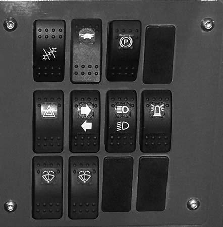
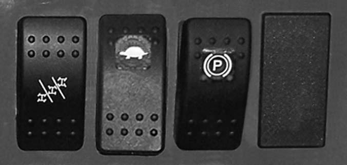
Top Row Switches
Switches have graphic symbols to indicate function and effect. The following mode descriptions start with the first switch on the left.
Warning
Unattended machine hazard.
Activate parking brake switch and lower attachment tool to ground before leaving machine. An unattended machine can move or roll and cause death or serious injury to operator or bystanders.
Periodically check the parking brake operation to verify that it has adequate holding power. Always be sure the parking brake switch is off when resuming machine operation.
A - Steering Mode: This 3-position switch is used to select among the three steering modes. The upper position selects the 4-wheel steering mode. This mode selects all-wheel steering for making tighter turns, usually on a jobsite. The center position selects the 2wheel steering mode. This mode selects front wheel steering only, used for higher speed travel. The lower position selects the crab steering mode. This mode is used when a small amount of side shift is needed for picking or placing a load.
NOTE: The rear wheels are not self-centering. Make sure all wheels are in a straight-ahead position before changing the steering mode.
Any of the steering modes can be used in both forward and reverse travel. The operator should learn to anticipate changes in machine movement if the steering mode must be changed.
B - High/Low Speed: This switch is used to select the travel speed. Press the top of the switch to select low speed, used for load pickup and placement, or whenever low speed operation is desired. Press the bottom of the switch to select high speed, used for road travel.
IMPORTANT: Be sure machine is stopped before changing travel speeds.
C - Parking Brake: When the machine is parked, this switch should be pressed to actuate the parking brake mechanism in the front axle.
D - Blank
Middle Row Switches
Switches have graphic symbols to indicate function and effect. The following mode descriptions start with the first switch on the left.
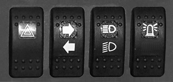
NOTE: Some switches are optional and may not be on machine.
E - Hazard: This switch can be activated to make the tail lights flash on and off in case the machine is stalled or temporarily stopped in a traffic area on the road or jobsite.
F - Turn Signal: This switch is used to indicate the direction of a turn with the tail lights. Press the right arrow for a right turn; press the left arrow for a left turn. Return the switch to the center position after the turn is completed.
G - Head Lights/Work Lights: Pressing the top of the switch will illuminate the lights mounted on the top of the operator’s station and the red tail lights for forward travel operations. Pressing the bottom of the switch will illuminate the lights at the end of the boom in addition to the lights on the operator’s station for additional lighting in working operations.
H - Strobe: When a beacon is installed on the machine, activating this switch will produce a strobe-light on and off flashing, for working in conditions that may obscure view of the machine.
Bottom Row Switches
Switches have graphic symbols to indicate function and effect. The following mode descriptions start with the first switch on the left.
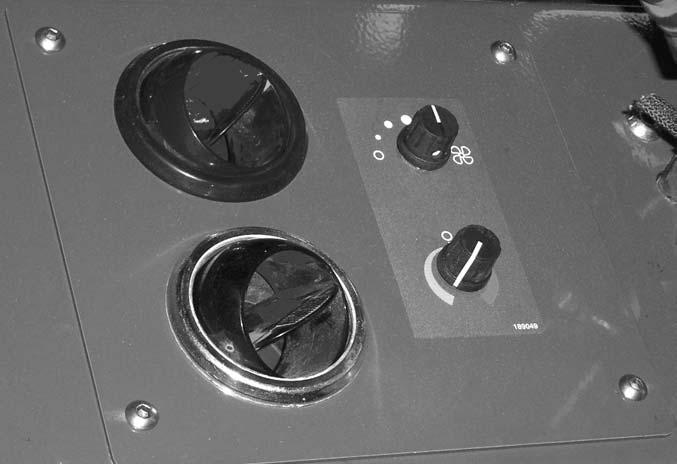
Fan Speed: This knob is located below the temperature control knob. Rotating the knob clockwise will increase the fan speed for increased air circulation.
Heater A/C Controls
NOTE: Some switches are optional and may not be on machine.
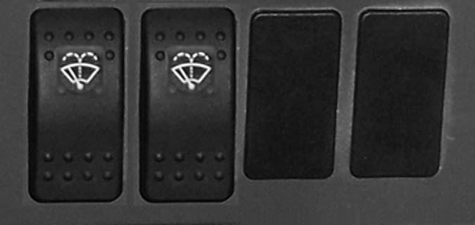
I and J - Wiper/Washer: The windshield and top window of the operator’s station are each equipped with a wiper and washer mechanism. The left switch (I) operates the wiper and washer on the windshield; the second switch (J)operates the wiper and washer on the top window.
K and L - Blank
Heater Controls
Temperature Control: This is the upper knob located to the left of the steering wheel. This knob is used to adjust the temperature output of the cab heater. Turning the knob clockwise will increase the temperature output.
Fan Speed: This is the upper knob located to the left of the steering wheel. The fan is in the off position when the knob is rotated completely to the left. Rotating the knob clockwise will switch the fan on and increase the fan speed for increased air circulation.
Temperature Control: This knob is located below the fan speed knob. It is used to adjust the temperature output of the heater A/C unit. Turning the knob clockwise from the midpoint position will increase the temperature output of the cab heater. Turning the knob counterclockwise from the midpoint position will switch the A/C unit on and decrease the temperature output of the cab A/C.

Travel Lever
Located on the left side of the steering wheel column, this lever is used to change travel direction (forward or reverse).
Position “F” (FORWARD)
Position “N” (NEUTRAL)
Position “R” (REVERSE)
NOTE: The lever MUST be in N (Neutral) position before the starter will engage to start the engine.
IMPORTANT: Care should be taken when changing direction, because damage to the hydrostatic transmission can occur if shifting is forced or attempted at too high a speed. Allow machine speed to slow before any directional change is attempted.

NOTE: Backup alarm automatically sounds with travel lever in reverse.
Steering
The power steering system is designed to provide loweffort steering without shock reaction from the axle wheels to the steering wheel. Turn the steering wheel to the right or left to turn the machine in that direction.
Floor And Seat Area
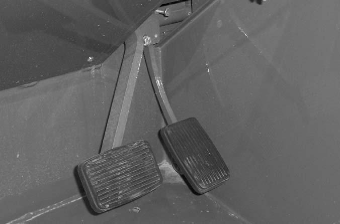
Throttle Pedal: This is right-foot operated and controls the engine speed to match increased power requirements. Pushing down on the pedal increases the RPM; letting up on the pedal decreases RPM.
Service Brake Pedal and Transmission Cut-off: Pressing the brake pedal hydraulically activates the internal braking mechanism in the front axle. During initial brake pedal travel and as the brake pedal is pressed farther, power to the transmission is progressively cut off. This allows faster engine speeds at slower operating speeds while maintaining power to the hydraulic system.
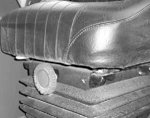
Suspension Seat (optional): In addition to the “A” latch handle for forward and rearward adjustment, this seat has a knob “B” under the front of the seat to adjust the suspension. Turn the knob to the right for a softer ride, and to the left for a firmer ride.
Seat Belt: This machine has a retractable seat belt. Grasp the belt on the left side of the seat pulling the belt over your lap and inserting the belt into the buckle on the right side of the seat until you hear it lock in place.
Brake Fluid Reservoir: Located in the front of the frame on the inside left wall under the cover.
Seat Positioning: The seat is mounted on rails for forward and rearward repositioning to accommodate the operator’s size. A springloaded latch handle under the front of the seat activates the adjustment mechanism.
Right Side Panel
These controls are used to position the boom and attachment. Graphic symbols indicate the control actions.
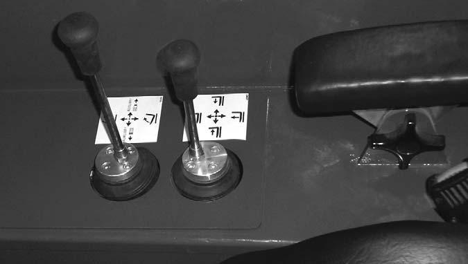
Boom Control Joystick: This machine has a hydraulic-type telescopic boom. The boom section extends by means of a hydraulic cylinder inside the boom.
To extend the boom, move the joystick handle to the right; to retract the boom, move the joystick handle to the left. To raise the boom, move the joystick handle rearward; to lower the boom, move the joystick handle forward.
Warning
Use extreme caution when raising or extending the boom. The Telehandler MUST be within safe lifting parameters as indicated by the frame angle indicator. Loaded or empty, this machine can tip if not level.
ALWAYS place the transmission in neutral, set the parking brake and keep the service brake pedal fully depressed before raising or extending the boom.
NEVER exceed the specified lift and reach capacities of this machine. Serious machine damage or personal injury may result. Refer to the load charts in the operator’s station or this manual.
If a boom circuit hose bursts with the boom up, with or without a load, shut down the machine following the Mandatory Safety Shutdown Procedure (page 8). DO NOT attempt repairs. Call your Mustang dealer for assistance.
Attachment Tilt/Auxiliary Hydraulics Joystick: To tilt the attachment tool up, move the joystick handle rearward; to tilt the attachment tool down, move the joystick handle forward. When the operator tilts the attachment tool to a desired angle, that angle will be maintained as the boom is raised and lowered, extended and retracted, until a new angle is set.
Move the joystick handle to the left or right to operate the additional hydraulics required on some attachment tools.
Warning
The truss boom attachment tool should ONLY be used to lift and place loads when the machine is in a stationary position. Transporting suspended loads must ALWAYS be done slowly and cautiously, with the boom and load as low as possible. Use taglines to restrict loads from swinging, to avoid overturn.
DO NOT tilt the truss boom back more than 45o from horizontal. Check the frame angle indicator before raising a load.
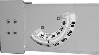
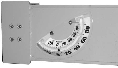
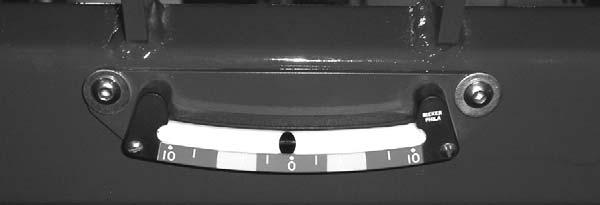
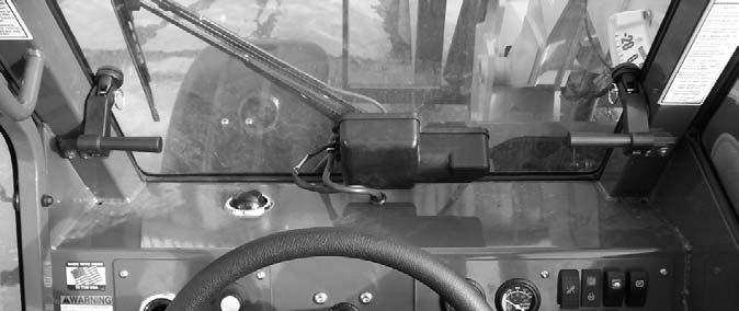
Function Indicators
Frame Angle Indicator: Located in front of the operator on the ROPS upper cross tube, this indicator enables the operator to check if the telehandler is at a safe angle for operation.
Boom Angle Indicator: Mounted on the left side of the outer boom, the position of the ball shows the angle of boom elevation relative to the ground.
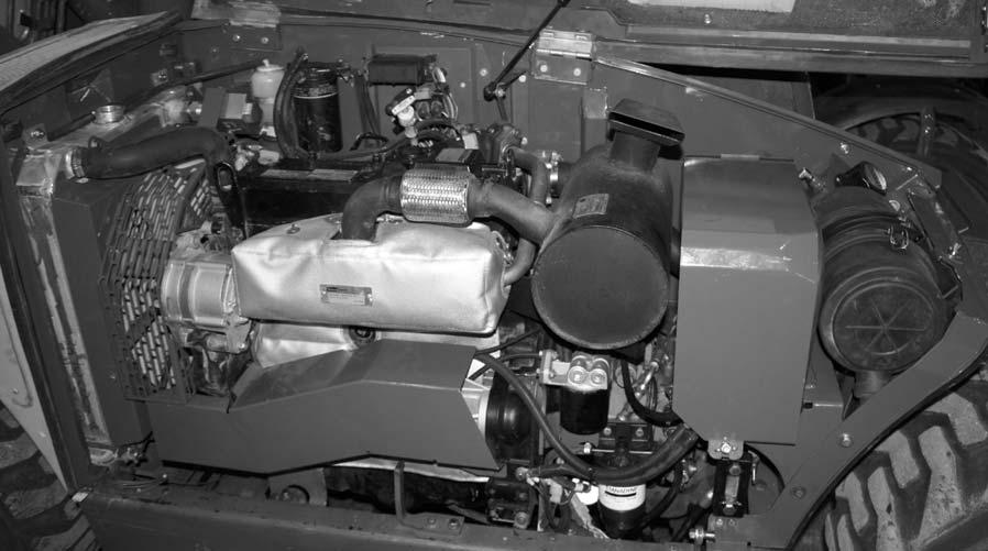
Service And Safety Features
The following indicators are for checking fluid levels.
Engine Oil Level: The yellow dipstick is located on the top of the engine about centered above the valve cover.
Hydraulic Reservoir Oil Level and Fill Cap: The hydraulic oil level sight gauge is located under the engine cover directly below the battery compartment. The hydraulic oil fill cap is located under the engine cover toward the front, just to the left of the air cleaner.
Coolant Level: The coolant expansion tank is located under the engine cover forward of the radiator on the backwall.
Hydraulic Restriction Indicator: This indicator is located on the multi-function display in the operator’s compartment. (Refer to Checking and Changing Hydraulic Return Filter Element, page 51.)
Air Filter Restriction Indicator: This indicator is located on the multi-function display in the operator’s compartment. (Refer to Checking and Changing Air Filter Element, page 52.)
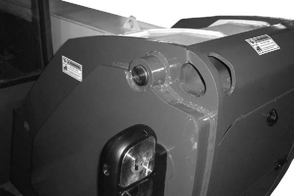
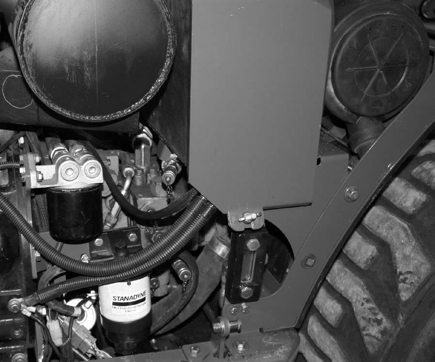
Hydraulic Pressure Test Port: Located off the lower portion of the battery compartment; a gauge can be attached to this port to check main valve and steering pressures
Battery: The battery is located under the engine cover toward the front of the engine compartment directly to the rear of the air cleaner. Remove wing nut and cover to gain access to the battery.
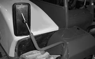
Left Side Rear View Mirror (optional): Located on the left side of the cab; it provides the operator a view of the area on the left side and behind the machine.
Backup Alarm: Located under the frame above the rear axle; it produces a loud warning sound whenever the machine is in reverse.
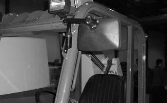
Right Side Rear View Mirror: Located on the right side of the machine; it provides the operator a view of the area on the right side and behind the machine.
Cab Right Side Window or Panel: Located on the right side of the cab; this window or panel protects the operator from coming in contact with the boom.
Cab Rear Window: Located on the rear of the cab; this window protects the operator from material flying off the rear wheel.
Front Window Emergency Exit: When equipped with the optional fully enclosed cab, the front window serves as an emergency exit. Pull the pin on each window hold-open, then push the window open and exit.
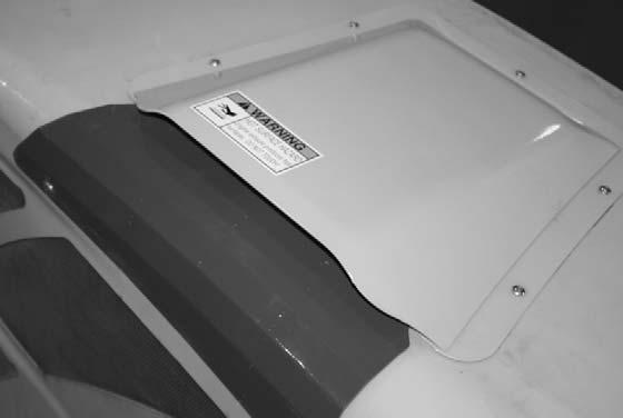
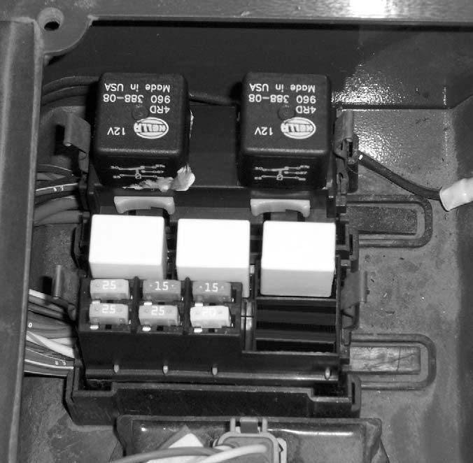
Operator Station Fuse and Relay Compartment: Located under the hinged load chart panel; lift the front of the panel to access the fuses and relays.
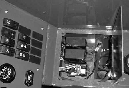
Operator Station Fuse and Relay Functions: Refer to the illustration and following description for the fuse and relay functions.
Engine Compartment Fuses and Relay Functions: Refer to the illustration and following description for the fuse and relay functions.
FUSES:
1.15 AMP Fuse: ignition switch, horn, brake lights
2.20 AMP Fuse: transmission, neutral start, park brake, steer mode, injector pump, backup alarm
3.15 AMP Fuse: lights, turn signals, hi/low speed
4.25 AMP Fuse: gauges, heater/hvac, alternator excitaton
5.25 AMP Fuse: top wiper motor
6.25 AMP Fuse: front wiper motor
RELAYS:
A.40 AMP Change-over Relay: park brake
B.40 AMP Change-over Relay: ignition
C.20 AMP Relay: lights
D.20 AMP Relay: top wiper
E.20 AMP Relay: front wiper
Engine Compartment Fuses, Relays and Solenoids: Located inside the engine compartment on the firewall.
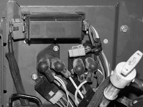
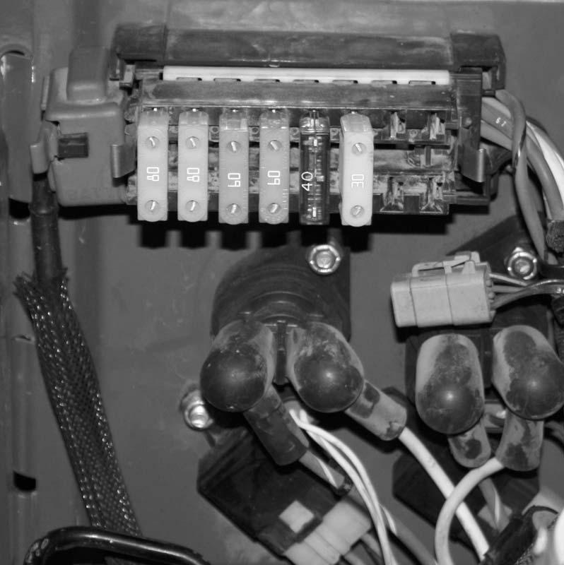
FUSES:
1.80 AMP Fuse: Alternator
2.80 AMP Fuse: Air Heater
3.60 AMP Fuse: Chassis Power
4.60 AMP Fuse: Starter
5.40 AMP Fuse: A/C Evaporator (when equipped)
6.30 AMP Fuse: A/C Condenser
SOLENOIDS:
A.Sarter
B.Air Heater
RELAYS:
C.20 AMP Relay: ECU
D.20 AMP Relay: Fuel Rack
Attachment Tools
Mustang offers a versatile range of attachment tools to meet various lifting and material handling applications. Contact your Mustang dealer for specifications and ordering information.
Accessories
Mustang offers a range of special accessories for this machine. Contact your Mustang dealer for specifications and ordering information.
NOTE: All accessories are field-installed unless otherwise noted. Information and parts for installing accessories are provided by the Mustang Manufacturing Company or Mustang Telehandler dealers.