9 minute read
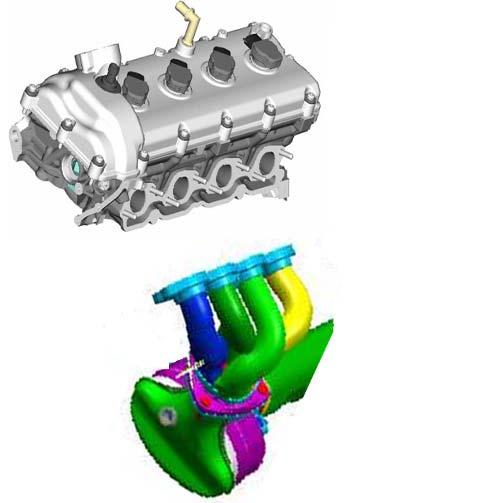
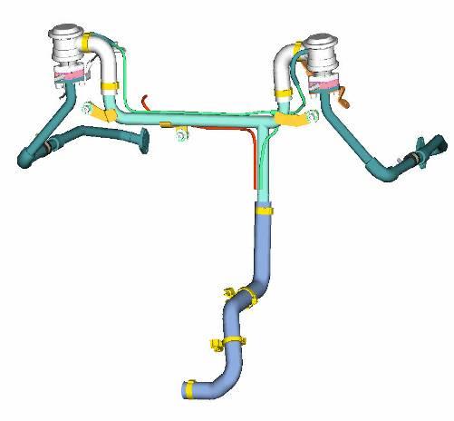
SECONDARY AIR SYSTEM


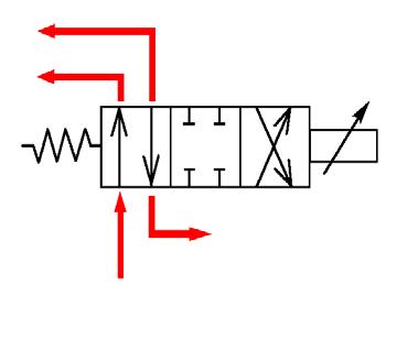
1.Solenoid valve
2.Pneumatic valves
3.Vacuum tank
4.Secondary air pump
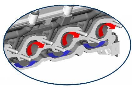
The secondary air system used on the wet sump engine is modifiedwith respect to the dry sump engine. The secondary air is now inserted in the specific ducts in the cylinder heads to improve warming up of the catalitycconverters and reduce further emissions. Through the solenoid valve (1) the MotronicECU controls opening/closing of the two pneumatic valves (2) that activate injection of secondary air directly into a channel machined into the engine head casting. The flow continues along its path through the communication holes between the channel and the exhaust duct to reach the exhaust manifold. The vacuum tank (3) that accumulates the vacuum necessary to open the pneumatic valves is positioned in the engine compartment underneath the secondary air pump. The secondary air pump (4), controlled by the engine ECU, sends air to the exhaust ducts. The pump and the secondary air solenoid valve are activated, after engine ignition, when the coolant temperature is in the range -7 °C and +40°C. The temperature threshold of 40°C disables the operating of the system. During the system operating cycle, the seal of the secondary air valves is checked. Throughout the cycle, the oxygen sensors are in “open loop”configuration and therefore do not activate the feedback for A/F ratio correction.
Variable Valve Timing
The Variable Valve Timing (VVT) system is modified with respect to the F136 R/S engine. The system uses a hydraulic VVT-actuator on each intake camshaft which is operated by engine oil pressure (low pressure type). The VVT-actuator consists of a external part (stator), which is fixed to the timing gear, and an internal part (rotor), which is fitted on the intake camshaft. The mutual shape of rotor and stator internallycreate different chambers: four advancing chambers and four retarding chambers. The division of oil pressure in the advancing chambers and retarding chambers determines the position of the VVT-actuator.
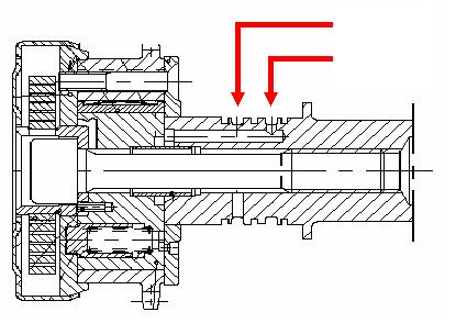
Inside the VVT-actuator, a clock spring is installed. The applying force of thespring is assisting the oil pressure when moving the rotor in the forward (advancing) direction. This is necessary because of the high valve operating reaction forces, tending to move the rotor in its backward position.
Inside the rotor of the VVT-actuator, a locking pin is installed. When the VVT-actuator is in its rest position, the locking pin is pushed into the stator by the force of a spring. In this condition the VVT-actuator is mechanically locked in its maximum retarded position. When the VVT-actuator is operated, the locking pin is lifted by oil pressure and the rotor is unlocked.
Advancing channel Retarding channel
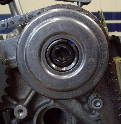
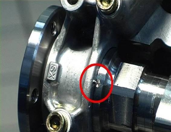
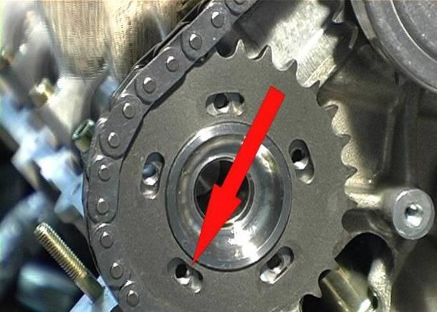
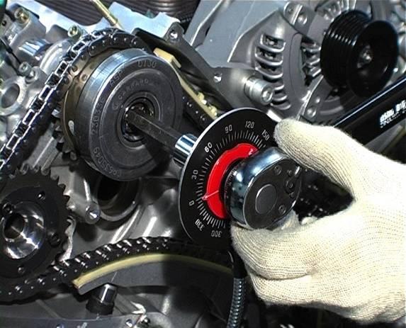
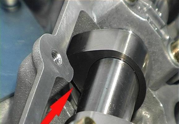
Note: when removing/installing the VVT-actuator, always make sure the actuator is locked in its rest position. This can be verified by means of reference marks on the actuator housing (see picture). Engine timing procedure can only be performed correctly when the VVT-actuators are in their rest position.
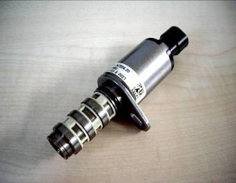
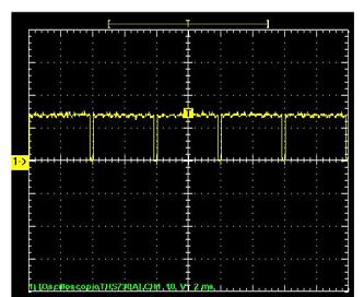
Each VVT-actuator is regulated by a solenoid valve which controls the oilsupply towards the advancing chambers and retarding chambers. The solenoid valves are directly controlled by the engine control module (NCM) by means of a pulse width modulation signal (PWM) and on the basis of a pre-programmed map (function of engine load and engine speed). The engine control module constantly monitors the actual position of the VVT-actuators by comparing the signals from the crankshaft position sensor and the camshaft position sensors. When the oil control solenoid valve is in its rest position, the oil supply is connected to the retarding channel, while the advancing side circuit is drained towards the sump.
Advancing
Retarding
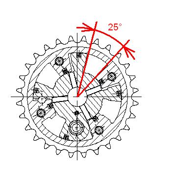
The timing of the intake camshafts can be modified continuously between maximum retarded and maximum advanced position. The VVT-actuator has an operating range of 25 degrees, corresponding to 50 crankshaft degrees.
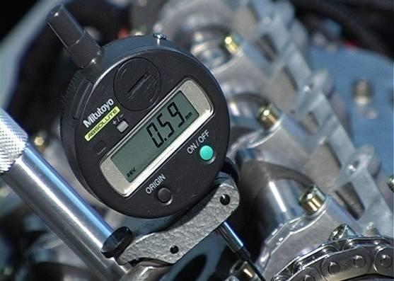
• VVT-actuatorin rest position(retarded): intakevalvesopen at 15°atdc (correspondingto0,59 mmvalvelift)
• VVT-actuatorfullyoperated(advanced): intake valvesopen at 35°btdc (correspondingto0,59 mmvalvelift)
Engine idling: intake timing is retarded. Late opening of the intake valves minimizes valve overlap. This guarantees stable combustion and smooth idling.
Low and middle revs, medium to high load: intake timing is advanced. Early opening of the intake valves creates high valve overlap. Exhaustgasses are partially re-burned which lowers combustion temperature and reduces emissions of NOx. Early closing of the intake valves at low revs improves volumetric efficiency.
High revs, full load: intake timing is retarded. Late closing of the intake valves improves volumetric efficiency as a result of the high inertia of the incoming air.
Note: whenswitchingoffthe engine, the solenoidvalveis broughtback tothe retardedposition, thistomakesurethe VVT-actuatorreturns toitsrest position, againstthe forceof the internalspring.
ENGINE TIMING:
Intake
Opening afterTDC 15°±1°
Colsingafter BDC66°±1°
(referencevalve lift: 0,59 +-0,08 mm)
Exhaust
Opening beforeBDC41°±1°
Closingat TDC 0°±1°
(referencevalve lift: 0,57 +-0,08 mm)
Intaketiming adjustment:
•Turn the crankshaftby 15° beyond the TDC. This corresponds to a piston stroke of 1.75 mm beyond the TDC
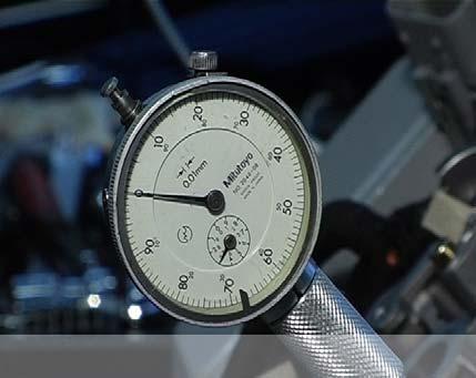
•Checkthat the tappet downstroke(begun before the TDC) and hence the intake valve opening is 0.59±0.08 mm
Exhausttiming adjustment:
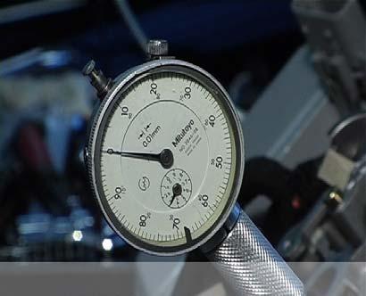
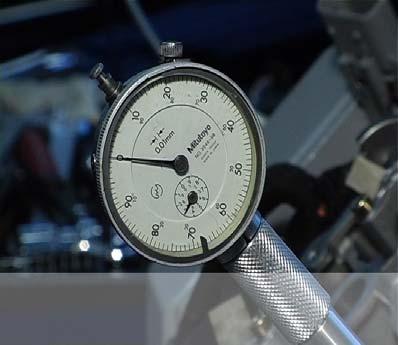
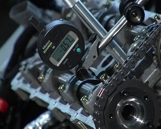
•Turn the engine clockwise and position the first piston at the TDC with the camshafts balanced (exhaust closed and intake open). Make sure that the dial gauge is on zero.
•Position the dial gauge plunger on the tappet of an exhaust valve. The dial gauge rod must be as perpendicular as possible to the tappet surface.
•Reset the dial gauge that measures the movement of the exhaust tappet.
•Turn the crankshaft clockwise until an exhaust valve is closed.
•Check that the tappet downstrokeand hence the exhaust valve opening is 0.57±0.08 mm.
Note: the givenvaluesare withthe VVT-actuatorin it’srest position, this correspondswiththe intake camshaftin the positionof maximum retarding, always check if the VVT-actuator is returned in its rest position.
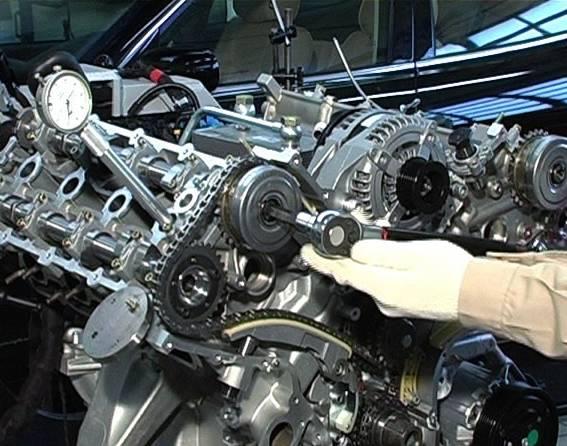
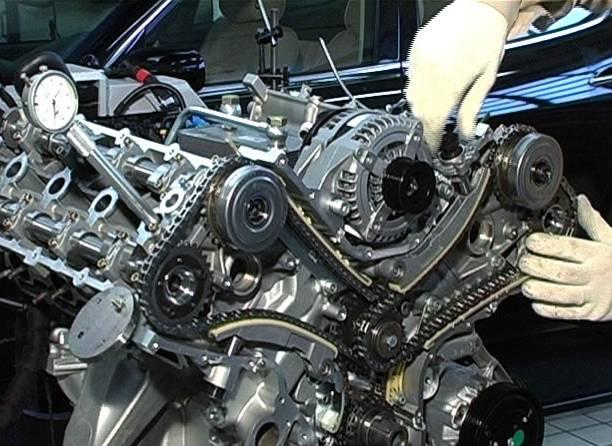
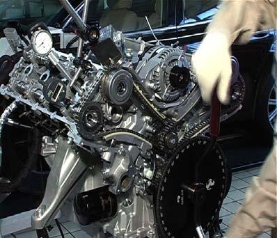
Intake Timing Adjustment Procedure
Note: The timing adjustmentprocedure onthe nextpages usesanengine with complete disassambledtiming mechanismas a startingpoint. Followthe different indicatedsteps carefullytoobtaincorrect engine timing and toprevent mechanical damage.
1.Turn the crankshaft until the crankshaft tab is in the 9.00 o’clock position.
2.Rotate the intake and exhaust camshafts on both banks until the reference marks at the ends of the camshafts match the reference marks on the camshaft caps.
3.Lock the camshafts so they cannot rotate.
4.Position a centesimal dial gauge and rotate the crankshaft clockwise until reaching TDC.
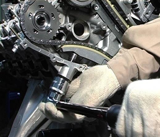
5.Make sure that the coupling surfaces between timing variators and camshafts are perfectly clean.
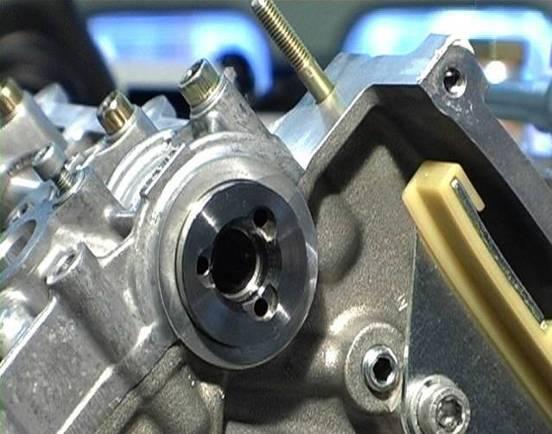
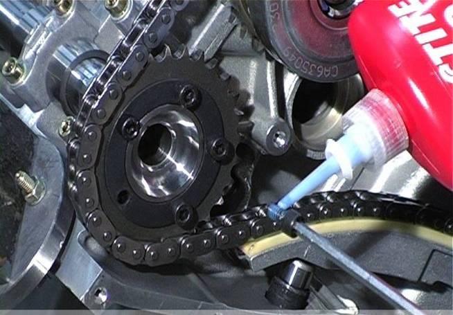
6.Before fitting the timing chains, position the timing variators on the camshafts by loosely tightening the fastening bolts by a few millimetres. Note: each time the timing variatoris removed, the fastening bolt should be replaced by a new one!
7.Position the camshaft driving chain on the right hand side bank.
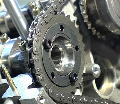
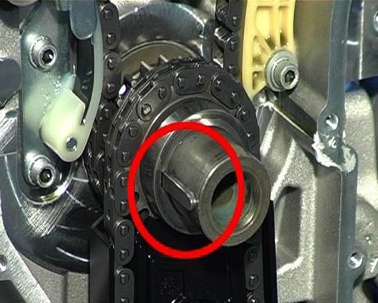
8.Position the exhaust side gear by making sure that the corresponding slots are placed in the centre of the adjustment area.
9.Position the right hand side hydraulic chain tensioner.
10.Tighten at least two fastening screws of the right hand exhaust gear.
11.Tighten the fastening bolt of the right hand side variator with a torque of 40 Nm.
12.Position the camshaft driving chain and gears on the left hand side bank by making sure that the corresponding slots of the exhaust side gear are placed in the centre of the adjustment area.
13.Position the left hand side hydraulic chain tensioner.
14.Tighten at least two fastening screws of the left hand exhaust gear.
15.Tighten the fastening bolt of the left hand side variator with atorque of 40 Nm
16.Fit the hydraulic chain tensioners by tightening them to 40 Nm torque by using a torque wrench.
17.Unlock the camshafts.

18.Rotate the engine in clockwise direction by making sure there isno jamming.
19.Position piston No. 1 at TDC and make sure that the corresponding dial gauge is set to zero.
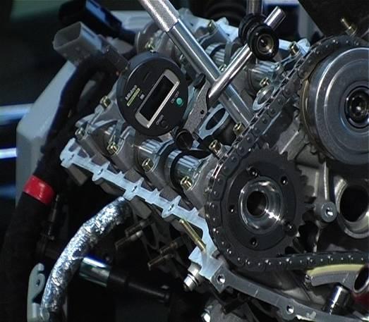
20.Position a magnetic base with its own centesimal dial gauge and long stem. The dial gauge stem must be placed in a position which is as perpendicular as possible with respect to the intake tappet surface.
21.Rotate the engine in clockwise direction by positioning the intake cam just before the opening position. The hydraulic tappet is still in the rest position. Reset the dial gauge measuring the shift of the intake tappet inthis position.
22.Rotate the crankshaft clockwise until 15° beyond the TDC; this corresponds to a 1.75mm piston stroke.
23.Check if the downstroke of the tappet (which began before the TDC), consequently the opening of the intake valve, is 0.59 ±0.08 mm.
24.If under such circumstances the measured values do not fall within the tolerance range, make sure that the crankshaft is locked into place and then slacken the timing variator fastening bolt and rotate the intakecamshaft until the preset valve upstroke intake value is met.
25.Double check the timing values.
26.Tighten the timing variator fastening bolt to a torque of 50 ±1.5 Nm followed by an angle of + 85°±1° by using a torque wrench and goniometer.
27.Double check again the timing values.
Exhaust Timing Adjustment Procedure
1.Rotate the engine in clockwise direction and position the first piston at TDC with the camshafts in the overlap position.
2.Make sure that the corresponding dial gauge is set to zero.
3.Position a magnetic base with its own centesimal dial gauge and long stem. The dial gauge stem has to be placed in a position which is as perpendicular as possible with respect to the exhaust tappet surface.
4.Reset the dial gauge measuring the shift of the exhaust tappet.
5.Rotate the crankshaft in clockwise direction until the exhaust valves are fully closed.
6.Check the tappet downstroke (exhaust valve lift) and make sure that it measures 0.57 ±0.08 mm.

7.If under such circumstances the measured values do not fall within the tolerance range, rotate the crankshaft and reach the TDC position.
8.While locking the camshaft into place, slacken the M6 screws andcarry out the timing procedure by using the adjustment slots.
9.Double check the timing values.
10.Tighten the hexagonal head M6 screw to the prescribed torque of 5Nm followed by an angle of 50° after applying some Loctite 242.
11.Double check again the timing values.
12.Carry out the same procedure for the left-hand cylinder bank, positioning the dial gauge holder on cylinder number 8.
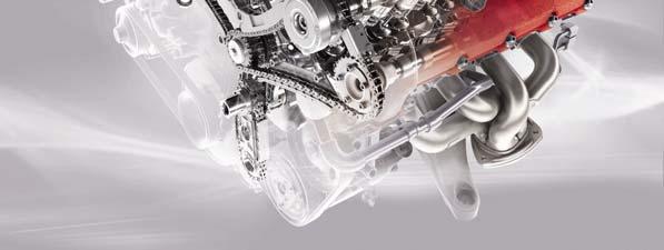
Introduction
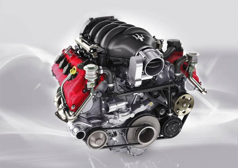
The new 4.7L engine is a technical evolution of the 4.2L engine,and also adopts the wet sump lubrication system for improved fuel economy, noise comfortand reliability. The increase in capacity from 4.2L to 4.7L has been obtained by an increase of both engine bore and engine stroke. For this purpose various engine components have been redesigned and the cylinder liners, now made from steel, use Nikasiltechnology.
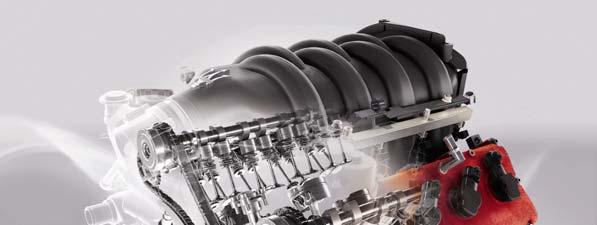
Nikasilis an electrodeposited nickel matrix silicon carbide coating with oleophilic characteristics. It reduces friction and wear and allows large cylinder bores with very small piston-cylinder liner tolerances. The 4.7L engine was designed to increase both engine power and torque in order to further improve the vehicle’s overall performances. They can be distinguished by the red painted valve covers.
The 4.7L engine comes in different versions. The differences between them lies in the intake and exhaust system, the variable valve timing system, specific engine mapping and whether the engine is combined with an automatic or a robotized transmission.
Engine Vehicle
F136YC
Alfa Romeo 8C
F136YE GranTurismoS MC-shift
F136YG Quattroporte S (MY09)
F136YH
Quattroporte Sport GT S (MY09)
GranTurismoS Automatic*
(*): to be launched in 2009
ENGINE CHARACTERISTICS:
The 4.7L engine (F136Y) is derived from the 4.2L wet sump engine(F136UC/UD) and has the following characteristics:
Short engine
•Newcrankcase in hardenedaluminium/silicionalloywithnewNikasil coated steel cilinder liners (the main dimensions of the crankcase have remained unchanged)
•Boreincreasedby2mm to94 mm
•strokeincreasedby4,7 mm to84,5 mm.
•New single-cast crankshaft in hardened steel, individually balanced, resting on five main bearings.
•New auxiliary drive belt crankshaft pulley with reduced diameter(same as F136S engine) to match higher engine speed.
•Newly designed connecting rods with specific big end bearings
•Newly designed pistons with specific piston rings
•Alsothe flywheel, lower crankcase, engine timing cover and numerous smaller components are specific for the F136Y engines.
Cylinder heads / timing mechanism
The cylinder heads are made in hardened aluminium/ silicon alloyand have high volumetric and thermodynamic efficiency combustion chambers. The cylinder heads and the engine timing mechanism have the samecharacteristics as on the F136UC/UD engines. The intake camshaft is however specific with a specific cam design to increase the maximum intake valve lift. (10,5 mm instead of 9,5 mm)
Lubricationsystem
The lubricationsystem hasthe samecharacteristicsason the F136UC/UD engines, with exceptionof:
•Specificoil jetsforpistonbottomcooling
•Nominaloil pressure: 4-5 bar @ 6000 rpm(100°C)
•Cancellationofthe oil levelswitchon the F136YC engine
•Installationofanoil temperature sensoron the F136YC engine(locatedat the rear end ofthe heatexchanger)
Coolingsystem
The coolingsystem hasthe samecharacteristicsasthe system on the F136UC/UD engines.
Crankcasevapourrecirculationsystem
The crankcasevapourrecirculationsystem hasthe samecharacteristicsasthe system on the F136UC/UD engines
Secondaryair system
The secondaryair system hasthe samecharacteristicsasthe system on the F136UC/UD engines.
Variablevalve timing system
The variablevalve timing system ofthe F136YC and F136YE engineshasthe same characteristicsasthe system on the F136UC/UD engines.
The variablevalve timing system ofthe F136YG and F136YH engineshasthe same characteristicsasthe system on the F136UC/UD engines, withexceptionofthe application ofa newtypeofVVT-actuator. The VVT-actuatoron the F136YG and F136YH engines hasanextendedadjustmentrange(60°insteadof50°). The basicintaketiming has thereforebeenretardedwith10°(range: -25°-35°)
SPECIFICATIONS:
F136YC -F136YE –F136YG –F136YH
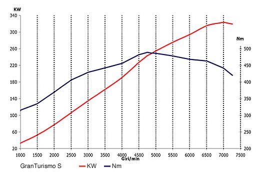
ENGINE PERFORMANCE CURVES (F136YE)
Engine Timing
The engine timing adjustmentprocedure of the F136Yenginesis similartothe procedure used forthe F136UC/UDengine. The timing valueshoweverare specific.
Intake timing adjustment F136YC and F136YE engine:
Turn the engine to 15° afterTop Dead Center, correspondingwitha piston strokeof 1,86 mm. The intaketappet downstroke shouldmeasure 0,60 ± 0,08 mm
Intake timing adjustment F136YG and F136YH engine:
Turn the engine to 25° afterTop Dead Center, correspondingwitha piston strokeof 5,09 mm. The intaketappet downstrokeshouldmeasure 0,60 ± 0,08 mm
Exhausttiming adjustment (all F136Y engines):
With the cranckshaftin Top Dead Center withthe engine in overlap position, the exhausttappet downstrokeshouldmeasure 0,60 ± 0,08mm
Caution Caution
Note: the engine timing values are specific for the different evolutions of the wet sump engine family!
Note (2): the givenvaluesare withthe VVT-actuatorin it’s rest position, thiscorrespondswiththe intake camshaftin the positionof maximum retarding. Always check if the VVTactuator is returned to its rest position.


