6 minute read
SECONDARY AIR SYSTEM


This system supplies additional air to the exhaust manifolds to allow the catalytic converter to reach their operating temperature quickly. By means of the solenoid valve (1), the MotronicECU, drives the opening/closing of the two pneumatic valves (2) which actuate the injection of secondary air into the exhaust manifolds (7). The vacuumtank (3) which creates the vacuum required to open the pneumatic valves is located in the engine compartment, underneath the secondary air pump.The secondary air pump (8), managed by the engine ECU, sends air to the exhaust lines.
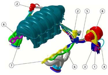
The pump and the secondary air solenoid valve are activated, after engine ignition, when the coolant temperature is in the range -5 °C to-99°C The function is active for around 80 seconds, deactivatesforaround 60 seconds and then reactivates for a further 10 seconds. In the latter period the secondary air valve seal is monitored.
The Lambda sensors are disabled for the entire duration of the cycle.
ENGINE TIMING:
The enginetiming data forforM138 and M139 vehicles are notthe same. Refertothe respectivetiming values foreachengineversion. CAUTION!
The engine timing procedure is identical for both versions, but the values will, of course, be different. The procedure below refers to F136R engines. The different tactics to adopt for F136S engines are described at the end of this timing procedure.
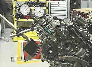
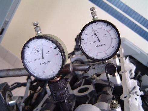
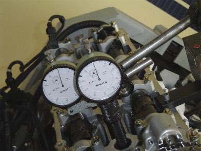
•Turn the engine anticlockwise and position the first piston at the TDC. Make sure that the dial gauge is on zero.
•Place a support for the magnetic base of the dial gauge holder on the right-hand engine head.
•Position a magnetic base with a long-rod centesimal dial gauge.
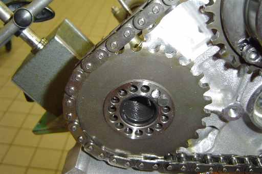
•Turn the engine clockwise positioning the intake cam immediatelybefore the opening ramp.
•In this condition, the hydraulic tappet is still in the rest position.
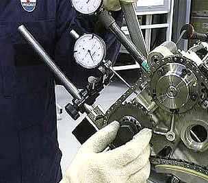
•Position the dial gauge plunger above the tappet of an intake valve. The dial gauge rod must be as perpendicular as possible to the tappet surface.
•Reset the dial gauge that measures the movement of the intake tappet.
•Again, position at the TDC and check the dial gauge previously reset. In this position (TDC), the intake valves of the first cylinder have already started their travel. Therefore, carefully check the position on the dial gauge positioned on the tappet.
•Turn the crankshaft 15° beyond the TDC. This corresponds to a piston stroke of 1.75 mm beyond the TDC.
•Check that the tappet downstroke(begun before the TDC) and hence the intake valve upstroke is 0.59±0.08 mm.
•Should the values measured in these conditions be out of tolerance, hold the crankshaft still, loosen the Allen screws on the timing variatorand turn the intake camshaft until obtaining the desired intake valve upstroke. For this reason, as described earlier, it is advisable to get ready for the timing procedure by positioning the variatoradjustment slots in the centre of the angular adjustment.
•Checkthe timing again.
•Use a torque wrench to tighten the previously loosened Allen screws that secure the variatorto a torque of 15 Nm, after applyingLoctite242.
EXHAUST TIMING ADJUSTMENT PROCEDURE (F136R)
•Turn the engine clockwise and position the first piston at the TDC with the camshafts balanced (exhaust closed and intake open). Make sure that the dialgaugeison zero.
•Position the dial gauge plunger above the tappet of an exhaust valve. The dial gauge rod must be as perpendicular as possible to the tappet surface.

•Reset the dial gauge that measures the movement of the exhaust tappet.
•Turn the crankshaft clockwise until an exhaust valve is closed.
•Check that the closing stroke of the exhaust valve is 1.09±0.08 mm.
•Should the values measured in these conditions be out of tolerance, hold the crankshaft still, move the centering dowel anticlockwise or clockwise (depending on whether you want to delay or anticipate the shaft) until obtaining the desired timing value.
•Insert the fixing dowel into the hole immediately after or before the centering dowel, whichever is easier.
CAUTION!
The tightening action of the exhaust gearwheel considerably affects the exhaust timing adjustment. Take this into account when adjusting the exhaust timing to the indicated value.
•Use a torque wrench to tighten the M20x32 mm hex-head screw of the exhaust camshaft(with relevant washer) to a torque of 200 Nm after applyingLoctite242.
•Checkthe timing again.
CAUTION!
Tighten the M20x32 screw to the indicated torque taking care to lock the exhaust camshaft so that the timing chain is not loaded.
•Carry out the same procedure for the left-hand cylinder bank, positioning the dial gauge holder on cylindernumber8.
INTAKE TIMING ADJUSTMENT PROCEDURE (F136S)
•Turn the engine anticlockwise and position the first piston at the TDC. Make sure that the dialgaugeison zero.
•Place a support for the magnetic base of the dial gauge holder on the right-hand engine head.
•Position a magnetic base with a long-rod centesimal dial gauge.
•Turn the engine clockwise and position the intake cam immediately before the opening ramp. In this condition, the hydraulic tappet is still in restposition.
•Position the dial gauge plunger above the tappet of an intake valve.
•The dial gauge rod must be as perpendicular as possible to the tappet surface.
•Reset the dial gauge that measures the movement of the intake tappet.
•Again, position at the TDC and check the dial gauge previously reset. In this position (TDC), the intake valves of the first cylinder have already started their travel. Therefore, carefully check the position on the dial gauge positioned on the tappet.
•Turn the crankshaft 15° beyond the TDC. This corresponds to a piston stroke of 1.75 mm beyondthe TDC.
•Check that the downstrokeof the tappet (begun before the TDC) and hence the valve upstroke is 0.59±0.08 mm.
•Should the values measured in these conditions be out of tolerance, hold the crankshaft still, loosen the Allen screws of the timing variatorand turn the intake camshaft until obtaining the desired intake valve upstroke. For this reason, as described earlier, it is advisable to get ready for the timing procedure by positioning the variatoradjustment slots in the centre of the angularadjustment.
•Checkthe timing again.
•Use a torque wrench to tighten the previously loosened Allen screws that secure the variatorto
•a torqueof 15 Nm after applyingLoctite242.
EXHAUST TIMING ADJUSTMENT PROCEDURE (F136S)
•Turn the engine clockwise and position the first piston at the TDC with the camshafts balanced (exhaust closed and intake open). Make sure that the dial gaugeison zero.
•Position the dial gauge plunger above the tappet of an exhaust valve. The dial gauge rod must be as perpendicular as possible to the tappet surface.
•Reset the dial gauge that measures the movement of the exhaust tappet.
•Turn the crankshaft clockwise until an exhaust valve is closed.
•Check that the tappet downstrokeand hence the exhaust valve upstroke is 0.57±0.08 mm.
•Should the values measured in these conditions be out of tolerance, hold the crankshaft still, move the centringdowel anticlockwise or clockwise (depending on whether you want to delay or anticipate the shaft) until obtaining the desired timing value.
•Insert the fixing dowel into the hole immediately after or before the centeringdowel.
CAUTION!
The tightening action of the exhaust gearwheel considerably affects the exhaust timing adjustment. Take this into account when adjusting the exhaust timing to the indicated value.
•Use a torque wrench to tighten the M20x32 mm hex-head screw of the exhaust camshaft (with relevant washer) to a torque of 200 Nm after applyingLoctite242.
•Checkthe timing again.
CAUTION!
Tighten the M20x32 screw to the indicated torquetakingcare to lock the exhaust camshaft so that the timing chain is not loaded.
•Carry out the same procedure for the left-hand cylinder bank, positioning the dial gauge holder on cylindernumber8.
This new 4.2L wet sump engine (F136UC –F136UD) is derived from the F136S engine but has been deeply re-engineered and characterized by technical contents that substantially differentiate it from the previous version.
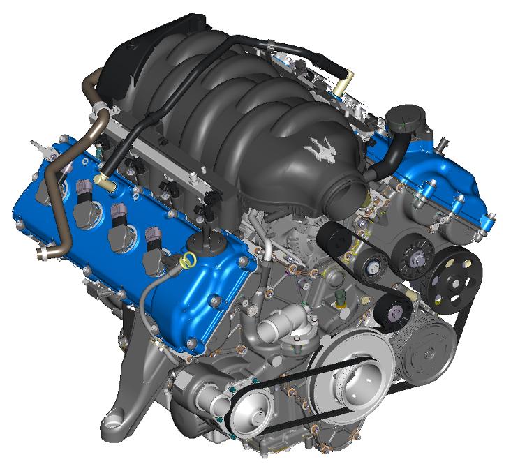
The most important technical innovation is the adoption of a wetsump lubrication system. High torque and power values have been maintained and are assured by the well known technical contents of the “Dry sump”engine. They have been optimised and reengineered for reliability.
This is a unit that forms part of the new generation of Maseratiengines, designed for the debut at the beginning of 2007 on Quattroportemodels with automatic gearbox. Little later this new engine also found its way under the bonnet of the all-new GranTurismomodel. Both engine versions (F136UC for QuattroporteAutomatic, F136UD for GranTursimo) are technically identical. The only difference lies in the engine control software with a specific engine mapping. This results in a more alert response to accelerator commands and a slightly higher power output for the GranTurismo.
ENGINE CHARACTERISTICS:
•Compact and lightweight construction (180kg)
•Short-stroke engine (bore: 92mm, stroke: 79,8mm)
•Cylinder heads in hardened aluminium/silicon alloy with high volumetric and thermodynamic efficiency combustion chamber.
•Crankcase in aluminium alloy and hardened silicon, completely redesigned with cast iron cylinder liners.
•Allthe conduits(water, oil, secondaryair) are madedirectlyin the enginecastingsto create a highlyrigid, space-savingsystem and providea strong guaranteeofquality duringassembly, and hencehigh reliability.
•Single-cast crankshaft in hardened steel, individually balanced, resting on five main journals
•Wet-sump lubrication system with oil pump integrated in the engine and oil-water exchanger integrated in the upper part of the crankcase.
•Cooling circuits operating by circulation of an antifreeze mixture, and water circulation pump driven by the engine pulley.
•Incorporatingthe auxillarysystems(water pump) withthe engine's maincastingsand the highlyrigiddesign ofallthe wide-wallelementsresultsin low enginenoiselevels and high componentreliability.
•Plastic intake manifold, with optimised line lengths.
•Steplessvariable valve timing system for the intake camshafts. It is activated by means of a low-pressure hydraulic system.
•Four overhead camshafts (two per bank) and four valves per cylinder, driven by hydraulic tappets.
•Timing controlled by chains whose tension is guaranteed by two hydraulic tensioners.
•Bosch MotronicME7.1.1 integrated ignition/injection system with motor driven throttle
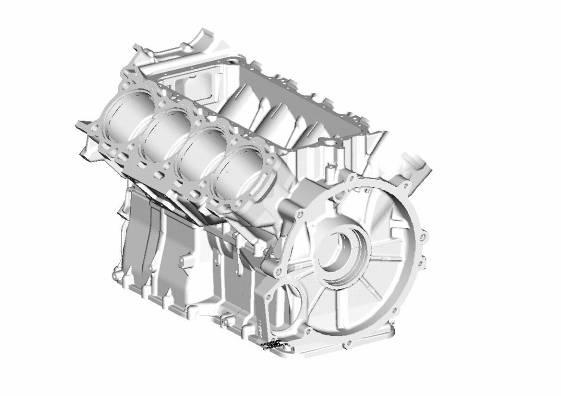
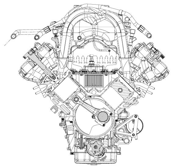
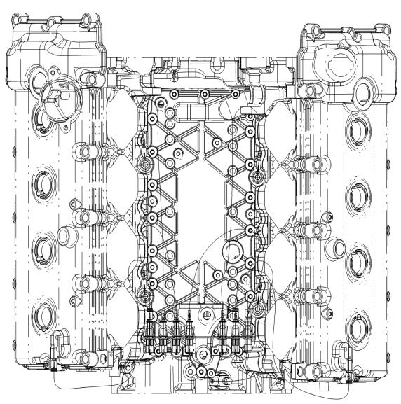
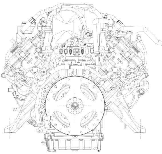
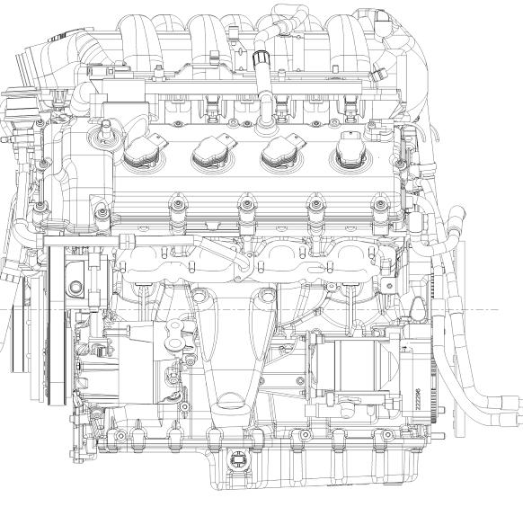
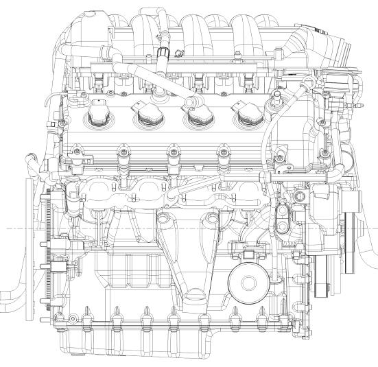
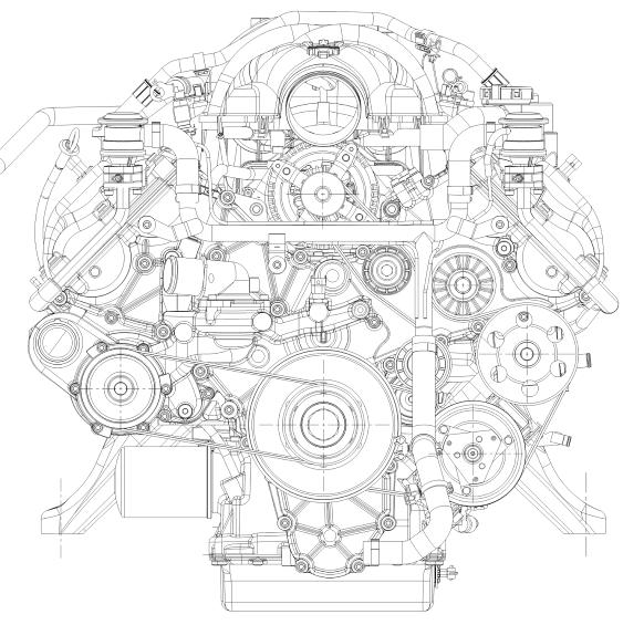
Engine Views
SPECIFICATIONS:
F136UC -F136UD