8 minute read
Inner Boom Removal and Installation (3-Section Boom

from Manitou MTA 12055 Series 3 Gehl DL11-44 55 GEN 3 Gehl DL12-40 55 GEN 3 Telescopic Service Manual

Fig. 765 - Remove Hoses
9 . Install caps and plugs on all hydraulic fittings to prevent contaminating the hydraulic system . 10 . Loosen and remove the nuts and bolts securing the hose tray to the inner boom bracket, and slide the hose tray back .
Advertisement
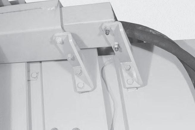
Fig. 766 - Remove Hose Tray Bolts
11 . Use a hoist and lifting strap around the intermediate/inner booms and pull both sections out from the outer boom approximately 12 inches .
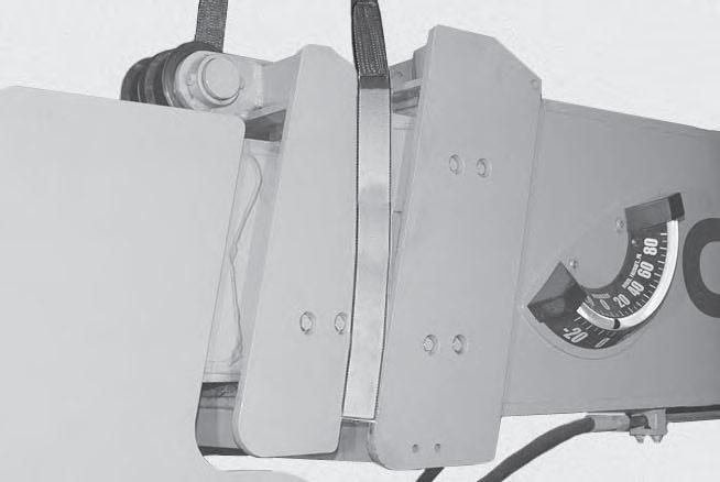
Fig. 767 - Pull Inner/Intermediate Booms Out
12 . Remove the hoist and lifting strap from the intermediate/inner booms.
13 . Use a hoist and lifting strap around the inner boom section . Pull the inner boom section from the intermediate section approximately 12 inches .
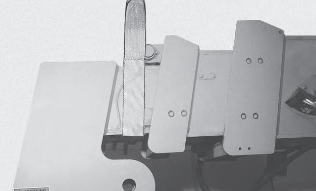
Fig. 768 - Pull Inner Boom Out 12”
14 . Loosen and remove the bolts (1), lockplate (2) and remove the two side slide pads and shims from the intermediate boom (both sides) .
1
1
2 1 2
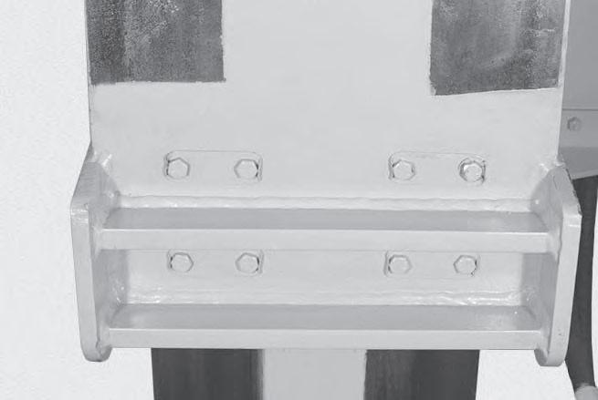
Fig. 769 - Remove Intermediate Side Slide Pads
15 . Loosen and remove the bolts, lockplates and remove the two top slide pads and shims from the intermediate boom .
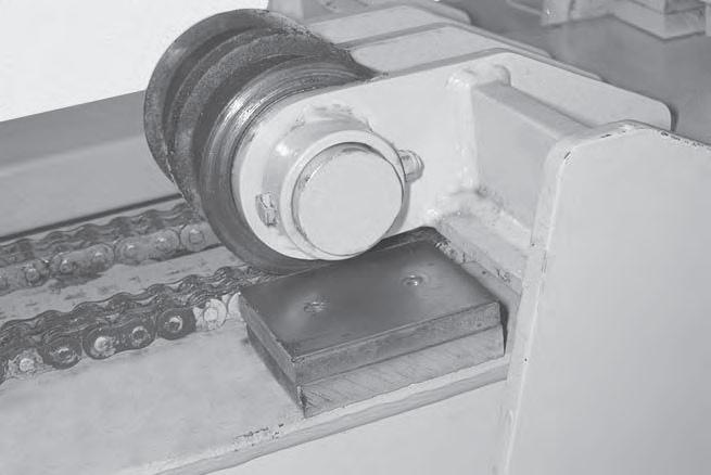
Fig. 770 - Remove Intermediate Top Slide Pads
16 . Using the hoist and lifting strap apply upward pressure on the inner boom . 17 . Loosen and remove the bolts (1), lockplates (2) in four places, and remove the two bottom slide pads from the intermediate boom .
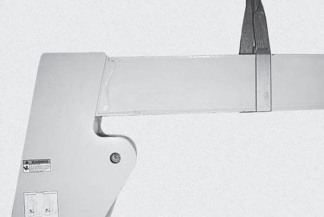
Fig. 771 - Remove Intermediate Bottom Slide Pads
18 . Begin sliding the inner boom section from the intermediate boom . Before the inner boom section is completely removed, put a wood block under the nose portion of the boom, and lower the inner boom so that the nose portion is resting on the block and remains level . 19 . Position the hoist and lifting strap on the inner boom at about 33 inches (as shown). This will allow a balanced lifting point .
33”
Fig. 772 - Position Lifting Strap
NOTE: Without any attachments on the boom. 20 . Remove the inner boom section from the intermediate boom .
Inner Boom Installation (3-Section Boom)
21 . With the inner boom section removed, apply grease to the inside bottom and top surfaces of the intermediate boom section where the pads of the inner boom will contact when assembled .
Use a brush attached to a rod or pole to reach inside the boom .
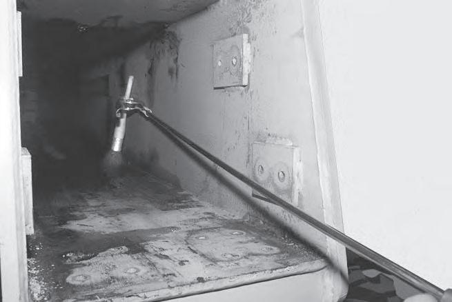
Fig. 773 - Grease Slide Surfaces
22 . Install the inner boom section into the intermediate boom .
23 . Slide the inner boom section into the intermediate boom up to the balance point, then reposition the lifting strap and slide the inner boom in until there is approximately 12 inches of the inner boom left section sticking out of the intermediate boom .
Fig. 774 - Slide Inner Boom into Intermediate Boom
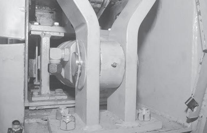
24 . Using the hoist and lifting strap, apply upward pressure to the inner boom . 25 . Reinstall the two bottom slide pads on the intermediate boom, using the lockplates (1) and bolts (2) in four places. Use Loctite 271 (red) Thread
Lock (or equivalent) on the threads of the bolts and tighten to 30 ft-lbs (40.7 Nm) torque. Bend each end of the lockplate up .
2 1
Fig. 775 - Install IntermediateBottom Slide Pads
26 . Using the hoist and lifting strap, lower the inner boom slightly . 27 . Reinstall the two top slide pads and shims on the front of intermediate boom. Use Loctite 271 (red) Thread Lock (or equivalent) on the threads of the bolts and tighten to 30 ft-lbs (40.7 Nm) torque.
Fig. 776 - Install Intermediate Boom Top Slide Pads
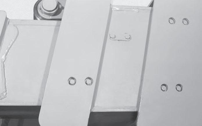
28 . Reinstall the two side slide pads and shims on the front of intermediate boom (both sides), using the lockplate (1) and bolts (2). Use Loctite 271 (red) Thread Lock (or equivalent) on the threads of the bolts and tighten to 30 ft lbs (40 .7
Nm) torque. Bend each end of the lockplate up.
1
2
2
Fig. 777 - Install Intermediate Boom Side Slide Pads
29 . Remove the lifting strap and hoist from the inner boom .
30 . Push the intermediate and inner boom sections fully into the main boom, this will allow enough room to reinstall the single chain . 31 . Reinstall the hose tray using the nuts and bolts .
Fig. 778 - Install Hose Tray

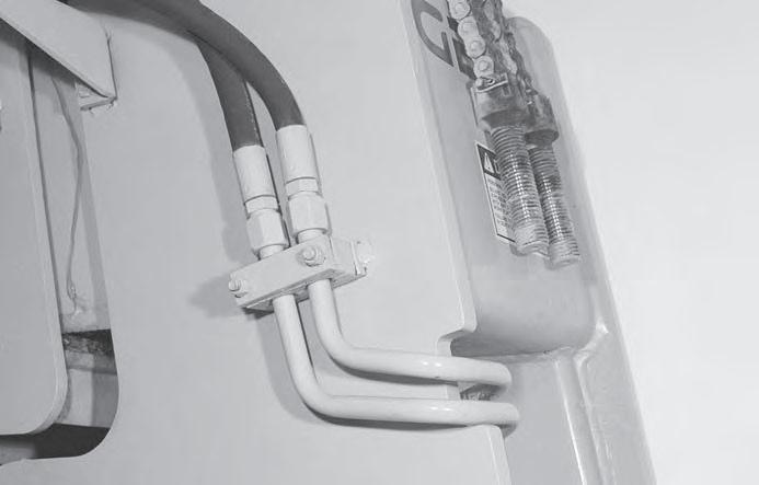
32 . Remove the caps and plugs from the hydraulic fittings. 33 . Reconnect the two hydraulic hoses to the tube lines connected to the tilt cylinder .
Fig. 779 - Connect Two Hydraulic Hoses
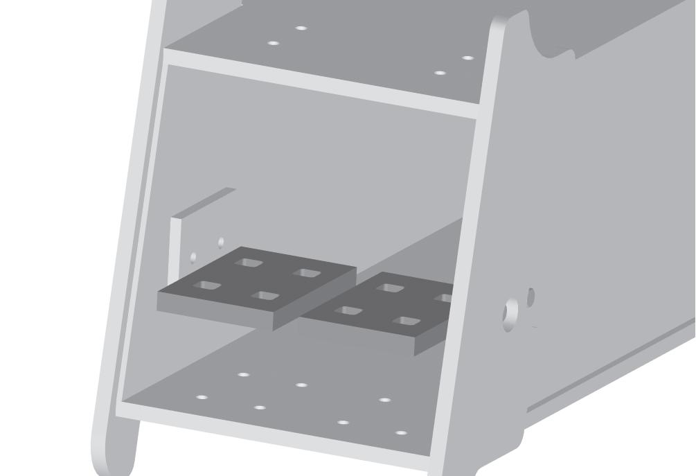
34 . Reinstall the four side slide pads and shims (1) and the two top slide pads and shims (2) to the rear of the inner boom using the lockplates (3) and bolts (4). Use Loctite 271 (red) Thread Lock (or equivalent) on the threads of the bolts and tighten to 30 ft-lbs (40.7 Nm) torque. Bend each end of the lock plates up .
2 2
1 3
4 3 1
Fig. 780 - Install Slide Pads On Rear Inner Boom
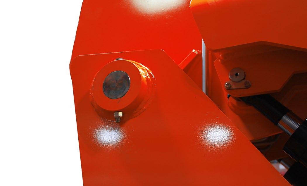
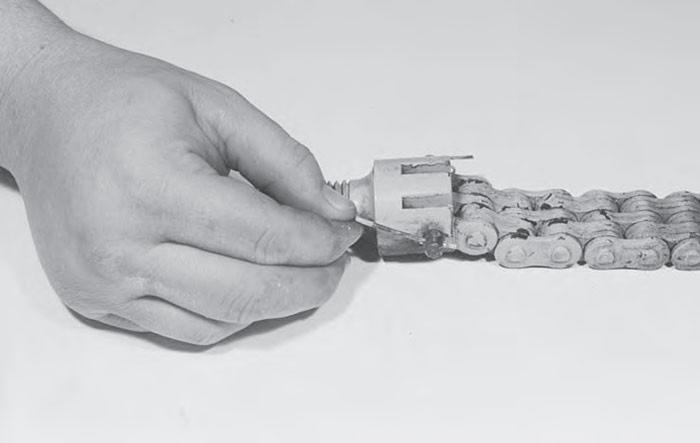
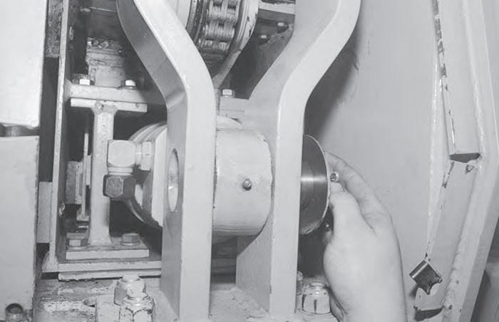
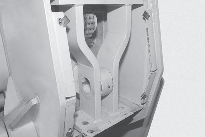
35 . Reinstall one of the nuts on the single chain clevis so that about 2-3/4 inch (70 mm) of the clevis is extending from the mounting bracket on the inner boom .
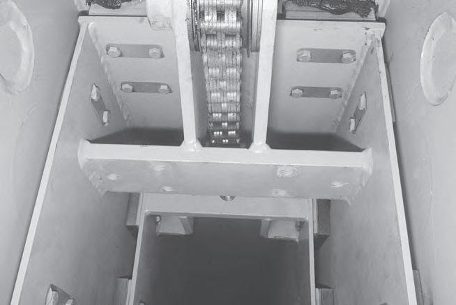
Fig. 781 - Install Single Chain Clevis
36 . Pull back on the single chain clevis to position the nut between the two bars on the bracket .
Check the amount of clevis extending from the bracket, then adjust to achieve the 2.75 inch (70 mm) dimension shown .
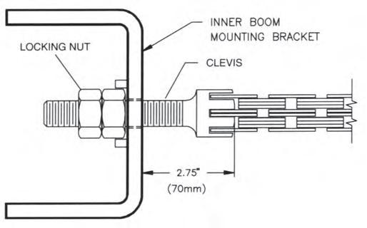
Fig. 782 - Adjust Chain Clevis
37 . Reinstall the three bolts and washers to secure the single chain clevis block to the outer boom .
Use Loctite 271 (red) Thread Lock (or equivalent) on the threads of the bolts .

Fig. 783 - Install Chain Clevis Block
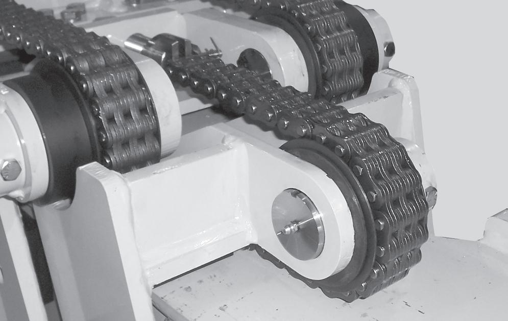
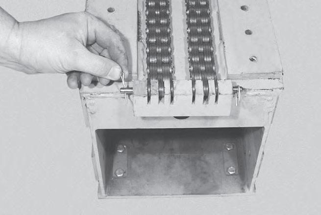
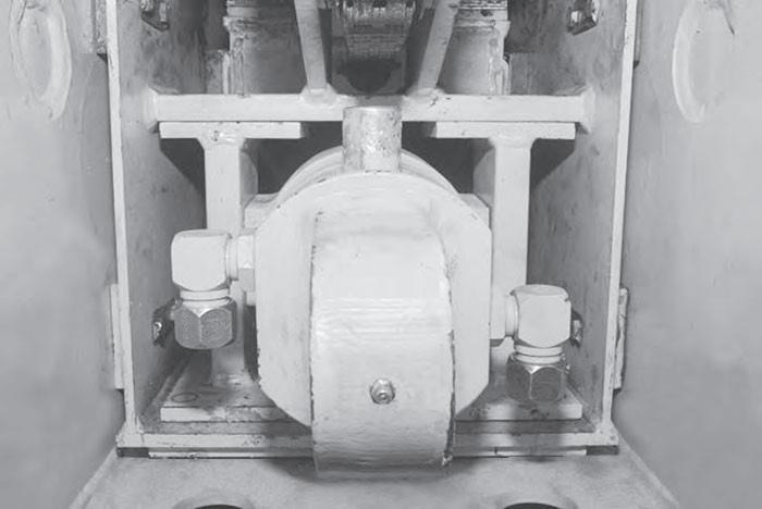
38 . Reinstall the double chain to the outer boom using the nuts. See “Leaf Chain Adjustment (3-Section Boom)” on page 386 in this manual to apply the final torque to the double chain assembly .

Fig. 784 - Install Bouble Chain to Outer Boom
39 . Reinstall the extend cylinder into the boom .
See Section 610 of this manual for correct procedure . 40 . Start the engine and check boom operation in a clear area .
41 . Shut down the engine and check for hydraulic fluid leaks. Correct any leakage problems found.
Extend Cylinder (3-Section Boom)
Mandatory Safety Shutdown Procedure BEFORE cleaning, adjusting, lubricating, fueling, or servicing the machine, or leaving it unattended:
• Bring the machine to a complete stop on a level surface . If the machine must be parked on a slope, park across the slope and chock the wheels to prevent movement . • Fully retract the boom and lower the attachment tool to the ground . • Idle the engine for gradual cooling . • Place controls in neutral .
• Apply the parking brake. • Shut off the engine and remove the key. ONLY when you have taken these precautions can you be sure it is safe to proceed . Failure to follow the above procedure could lead to serious personal injury or death.
Extend Cylinder Removal (3-Section Boom)
1 . Loosen and remove the six bolts from the rear cover and remove the cover from the boom .
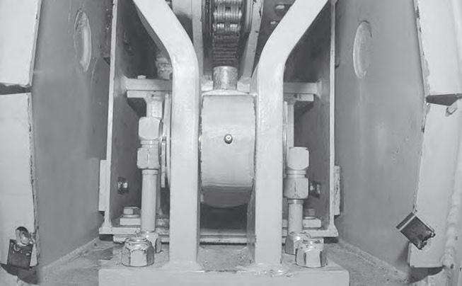
Fig. 786 - Mark Hydraulic Tubes
3 . Install caps and plugs on all hydraulic fittings to prevent contaminating the hydraulic system . 4 . Remove the cotter pin (1) and washer (2) from the cylinder pin .
1
2
Fig. 787 - Remove Cotter Pin and Washer
5 . Remove the cylinder pin (1) from the rod end .
1
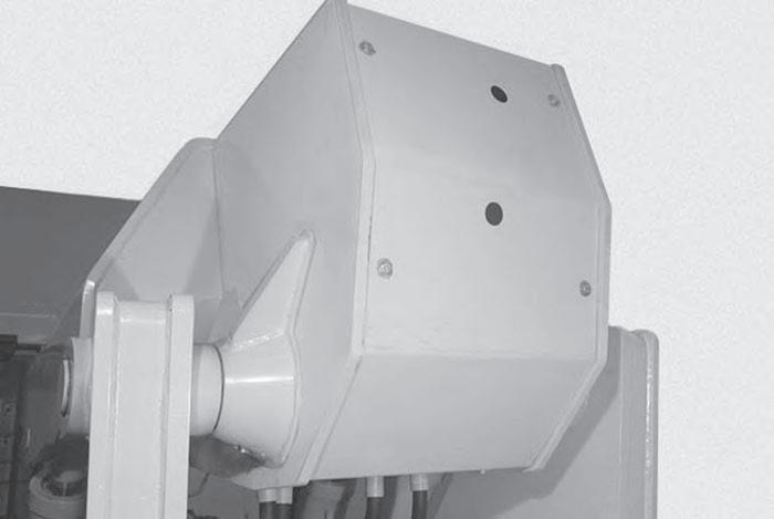
Fig. 785 - Remove Rear Boom Cover
2 . Mark the hydraulic tubelines for correct assembly. Loosen and remove the two tubelines from the extend cylinder .
Fig. 788 - Remove Pin 1
6 . Loosen and remove the eight bolts and nuts from the extend cylinder rod mounting bracket .
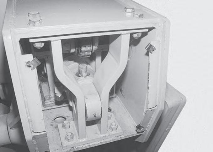
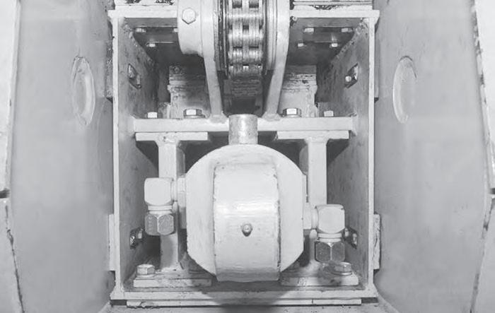
Fig. 789 - Remove Bracket Mounting Bolts
7 . Remove the extend cylinder rod end mounting bracket (1) and shim (2) .
1 1
Fig. 791 - Remove Trunion Mount Bolts
9 . Attach a hoist and lifting strap to the extend cylinder . Pull the extend cylinder and trunnion mounts (1) out the rear of the boom, remove both trunnion mounts from the cylinder .
1 1
1
2
Fig. 790 - Remove Mounting Bracket
8 . Loosen and remove the ten bolts from the trunnion mounts . Mark the trunnion mounts (1) for correct assembly .
Fig. 792 - Pull Extend Cylinder out of Boom
NOTE: As the extend cylinder is removed it will be necessary to reposition the lifting strap on the extend cylinder. 10 . Remove the extend cylinder from the boom .