36 minute read
6 Operation and Adjustments


Chapter 6
OPERATION AND ADJUSTMENTS
GENERAL INFORMATION
CAUTION
BEFORE starting the engine and operating the Telescopic Handler, review and comply with ALL safety recommendations in the SAFETY chapter of this manual. Know how to STOP the machine before starting it. Also, BE SURE to fasten and properly adjust the seatbelt.
ENGINE BREAK-IN
Your new engine does not require extensive “breakin.” However, for the first 100 hours of operation: Allow the engine to idle for a few minutes after every cold start, DO NOT idle the engine for long periods of time, DO NOT operate the engine at maximum power for long periods of time, and check the oil level frequently, and replenish as necessary with the oil specified in the engine manual. John Deere engines use a “break-in” oil for the first 100 hours of operation. After the first 100 hours of operation, change the oil and replace the oil filter. Consult the Lubrication chapter or the engine manual for the type of oil to use in the engine. Refer to the Service and Storage chapter for the proper service intervals.
PRE-START INSPECTION
Every Pre-start Inspection must include more than checking the fuel and oil levels. It is the operator’s responsibility to inspect the machine before the start of each workday. It is also a good practice to personally inspect any machine you are assigned to use, even if it has already been checked and put into service by other personnel. The most efficient method of checking a machine is by conducting a “Walk-Around Inspection.” The Pre-start Inspection and Daily Maintenance Handbook provided with your Telescopic Handler can be used as a guide for the “Walk-Around Inspection.”
BEFORE STARTING ENGINE
Before starting the engine and running the machine, refer to the Indicators and Controls chapter and familiarize yourself with the various operating controls, indicators and safety features.
STARTING THE ENGINE
Before mounting the operator’s compartment, walk completely around the machine to be sure no one is under, on, or close to it. Let others in the area know you are going to start the machine, and wait until everyone is clear.
WARNING
ALWAYS fasten the seatbelt BEFORE starting the engine. Leave the park brake applied until the engine is running and you are ready to operate the machine.
The following procedure is recommended for starting the engine: 1.Grasp the hand holds and step up into the operator’s compartment. 2.Adjust the seat and fasten the seatbelt. 3.Check that all controls are in their “neutral” positions, except the parking brake switch, which should be in the “ON” position. 4.Adjust the position of the steering wheel tilt console to provide comfortable handling. 5.Turn the keyswitch to “ON” position and press the start button. If the button is released before the engine starts, turn the keyswitch to “OFF” position, and allow the starter to stop before attempting to start the engine again. IMPORTANT: Crank the starter until the engine is started. If the engine fails to start within 30 seconds, return the key to the “OFF” position, wait two minutes, and try to restart the engine. Cranking the engine for longer than 30 seconds will result in premature failure of the starter.
6.After the engine starts, allow a 1-2 minute warmup time before attempting to operate the controls. 7.Check that indicators are in their normal operating condition. 8.Verify that there are no fuel, oil or engine coolant leaks, and no abnormal noises or vibrations.
COLD STARTING PROCEDURES
The engine is equipped with a block heater. This block heater or other starting aid is required for starting in temperatures below 32°F (0°C). See your Gehl dealer for additional starting aids.
For proper use of starting aids, check the instructions in the engine manual.
If the battery becomes discharged and has insufficient power to start the engine, jumper cables can be used for starting assistance. Refer to the jump starting instructions in the Service and Storage chapter of this manual for safe jump-start procedure.
STOPPING
The following procedure is the recommended sequence for stopping the machine: 1.Bring the machine to a stop on a level surface.
Avoid parking on a slope, but if necessary park across the slope and block the tires. 2.Fully retract the boom and lower the attachment to the ground. Idle the engine for gradual cooling. 3.Place controls in neutral. Set the parking brake switch to “ON.” 4.Turn the keyswitch key to the “OFF” position.
Remove the key. 5.Unfasten the seatbelt, and grasp the hand holds while climbing out of the operator’s compartment.
FIRST TIME OPERATION
Make sure the engine is warm and then go through the following procedures. Place the travel lever in a speed range and in Forward or Reverse. Turn off the parking brake switch and move slowly, while testing the steering and brakes. Stop and operate all boom functions and frame leveling controls, checking for smooth responses.
Apply the service brakes, and move the travel lever to the opposite direction (forward or reverse).
Shifting to the next higher gear may be done at any engine speed while the machine is in motion.
DO NOT overspeed the engine when down shifting. Allow the machine to slow down before shifting to the next lower gear.
CAUTION
Be sure the area being used for test-running is clear of spectators and obstructions. Initially, operate the machine with an empty attachment tool. ENGINE SHUTDOWN PROTECTION
The engine is equipped with a WARNING and SHUTDOWN feature that warns users of low engine oil pressure and of high engine coolant temperature. If the problem is not corrected, the engine power will be reduced automatically, or the engine will shut down.
Engine Oil Pressure
There are two low oil pressure protection features: Low Oil Pressure WARNING, and Low Oil Pressure SHUTDOWN.
At the Low Oil Pressure WARNING set-point, the warning lamp in the engine override switch will flash, and a slow engine power derate will begin. But if the oil pressure rises above the Low Oil Pressure WARNING set-point, power will slowly increase until the engine is back to full power. The lamp will continue to flash until the power has returned to normal, even if the fault condition has been corrected and the recovery is in process. At the Low Oil Pressure SHUTDOWN set-point, the warning lamp in the engine override switch will light continuously, and a fast engine power derate will begin. If the oil pressure does not rise above the SHUTDOWN set-point within 30 seconds, the engine will shut down. However, if the oil pressure rises above the Low Oil Pressure SHUTDOWN set-point within 30 seconds, then the power derate speed will revert to the Low Oil Pressure WARNING speed of reaction.
There are two coolant temperature protection features: High Coolant Temperature WARNING, and High Coolant Temperature SHUTDOWN. At the High Coolant Temperature WARNING setpoint, the warning lamp in the engine override switch will flash, and a slow engine power derate will begin. But if the coolant temperature drops below the High Coolant Temperature WARNING set-point, the power will increase slowly until the engine is back to full power. The lamp will continue to flash until the power has returned to normal, even if the fault condition has been corrected and the recovery is in process. At the High Coolant Temperature SHUTDOWN setpoint, the warning lamp in the engine override switch will light continuously, and a fast engine power derate will begin. If the coolant temperature does not drop below the SHUTDOWN set-point within 30 seconds, the engine will shut down. However, if the coolant temperature drops below the High Coolant Temperature SHUTDOWN set-point within 30 seconds, then the power derate speed will revert to the High Coolant Temperature WARNING reaction speed.
PARKING BRAKE
NOTE: The parking brake mechanism within the front axle is not designed for, and not intended to be used as, the primary means of stopping movement of the machine. Hydraulic braking provided through the service brakes within the axle is the primary means for stopping movement.
The proper sequence for correct machine operation is to always engage the parking brake switch before shutting off the engine, and to disengage the brake ONLY after the engine is running. In an emergency however, if it becomes necessary to stop movement, activate the parking brake switch to “ON.”
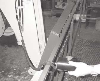
CHANGING ATTACHMENT TOOLS
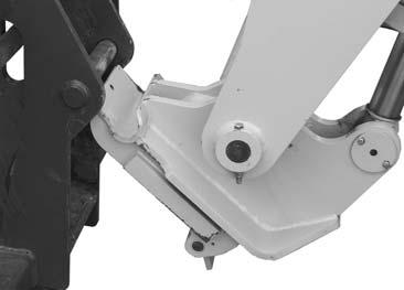
The Telescopic Handler boom nose will accept Quick Attach System Manitou attachment tools.The Quickattach System has a quick-release hookup and locking mechanism for mounting framing-type or masonry type attachment tools to the boom nose.
Attachment Tool Quick-Attach System Tilted Forward for Hook up
Attachment Tool Shown Locked to Quick Attach System
To pick up an attachment tool, proceed as follows: 1.Raise the boom slightly and extend it 2 or 3 feet (600 to 900 mm) for better visibility. Tilt the tool carrier forward. 2.Align the tool carrier squarely with the back of the attachment tool. 3.Slowly extend the tool carrier and lower the hooks under the attachment tool hookup bar. 4.Tilt the tool carrier back so that the lock plate engages the attachment tool. This secures the attachment tool to the Dynattach System. 5.For an attachment tool with auxiliary hydraulics, connect hoses to the quick-connect connectors on the boom nose.
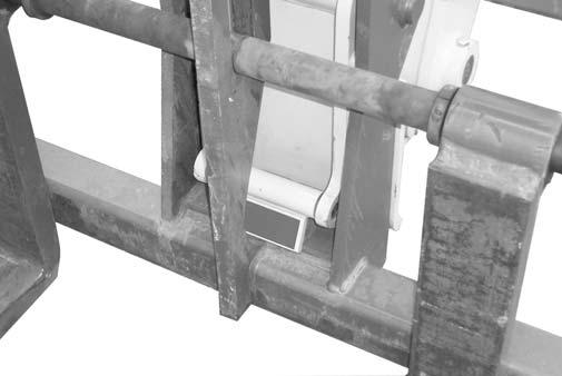
Attachment Tool Shown Unlocked for Release from Quick Attach System
Quick-Attach System Detaching Detail
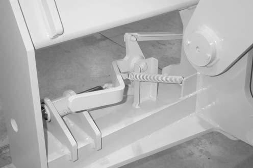
Detaching the Quick-attach System
To detach the attachment tool, proceed as follows: 1.Raise the boom slightly and extend it 2 or 3 feet (600 to 900 mm) for better visibility. Lower the boom until the attachment tool is approximately 12” (300 mm) off the ground. 2.Roll back the carrier as far as it will go. When the carrier is rolled back completely, perform the
MANDATORY SAFETY SHUTDOWN PRO-
CEDURE (Safety chapter p. 9). 3.With the engine off, leave the operator’s station and manually raise the lock spring and flip the lock plate up and outward at least 180° so that it is in position to re-lock onto the next attachment tool. 4.Tilt the tool carrier forward to allow the attachment tool to roll out, then lower the boom so that the hook ears clear the hookup bar on the attachment tool. NOTE: One side of the lock plate has a bright red decal to indicate the unlocked position.
5.If the attachment tool has auxiliary hydraulics, disconnect the hoses from the quick-disconnects on the boom nose. 6.Start the engine and roll the tool carrier forward.
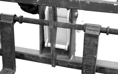
Slowly back the machine until the attachment tool is free from the boom nose. To pick up a bucket or material handling carriage tool, proceed as follows: 1.Rotate the lock lever completely to the left (counter-clockwise, as viewed from the operator’s station) to fully retract the lock pins. 2.Raise the boom slightly and extend it 2 or 3 feet (600 to 900 mm) for better visibility. Tilt the tool carrier forward. 3.Align the tool carrier squarely with the back of the attachment tool. 4.Slowly extend the tool carrier and tilt it forward until the support pins on each side are in-line with and slightly below the hookup ears on the back side of the attachment tool. 5.Slowly drive the machine forward, and, at the same time, roll the tool carrier back to engage the hookup ears on the attachment tool. Also, establish proper alignment of the carrier lock pins to the attachment tool. 6.Stop forward travel when the hookup ears are engaged, but continue to roll the tool carrier back to pick the attachment tool off the ground. When the tool carrier is rolled back completely, perform the MANDATORY SAFETY SHUTDOWN
PROCEDURE (Safety chapter p.9). 7.With the engine off, leave the operator’s station, and swing the lock lever completely to the right (clockwise, as viewed from the operator’s station) to fully engage the lock pins. 8.For an attachment tool with auxiliary hydraulics, connect the hoses to the quick-connect connectors on the boom nose.
LOCK LEVER
® Carriage Quick-attach System
WARNING
To prevent unexpected and undesired attachment tool release from the boom carrier, be sure to properly secure the quick-release lock pins by rotating the lock lever all the way to the right or inside. Modifications, alterations to, or use of attachment tools not authorized by Manitou N.A. Company can void the warranty and cause machine damage, and may result in serious personal injury or death.
SELF-LEVELING
The machine has a hydraulic self-leveling feature. This feature is designed to keep the attachment tool level while the boom is being raised.
GENERAL MACHINE OPERATION
Check the Telescopic Handler to be sure all systems are in good operating condition. Perform the following steps before starting the machine for the first time each day. 1.Check the engine oil, coolant, transmission oil and hydraulic oil levels. 2.Make sure weekly lubrication has been done. 3.Visually inspect for leaks, broken or malfunctioning parts. Make sure all caps, covers and safety shields are in place. 4.Check tires for cuts, bulges, nails, correct pressure, loose wheel nuts, etc. 5.Inspect the work area. Make sure you know where you will make load pickups, lifts, and turns. Look over the terrain of the jobsite for holes, obstacles, slippery surfaces, soft or deep mud. 6.Check clearances of ramps, doorways and passage ways. Check overhead clearances if you will travel and place loads near power or telephonelines. If the machine is found to be in need of repair or in any way unsafe, or contributes to an unsafe condition, the matter shall be reported immediately to the user’s designated authority. The machine should NOT be operated until it has been restored to a safe operating condition.
WARNING
Exhaust fumes can kill. Ensure proper ventilation when starting indoors or in enclosed areas.
Use proper grab handles, NOT the steering wheel or control levers as handholds when mounting or dismounting. NEVER operate the machine with safety guards or covers removed. Over-inflated tires can explode and cause injury or death. Tire repairs MUST be made only by authorized personnel using proper tools and equipment.
Operate the travel controls gradually and smoothly when starting, stopping, turning and reversing the directions.
Grade and Slope Precautions
The Telescopic Handler complies with industry stability tests requirements and is stable when properly operated. However, improper operation, faulty maintenance, or poor housekeeping may contribute to a condition of instability and defeat the purpose of the standard.
The amount of forward and rearward tilt to be used is governed by the application. Although use of maximum rearward tilt is allowable under certain conditions, such as traveling with the load fully lowered, the stability of the machine, as determined by the industry standard tests, does not encompass consideration for excessive tilt at high elevations, or the handling of offcenter loads.
Handle only loads within the capacity limits of the machine, and that are stable and safely arranged. When attachments are used, extra care should be taken in securing, manipulating, positioning and transporting the load.
Grade Limits
NOTE: Grade limits are based on ANSI/ITSDF standard B56.6-2005.
The telescopic handler meets or exceeds the safety standard (ANSI/ITSDF B56.6) stability limits for rough-terrain forklifts. The stability tipping limits
cover specific, controlled test conditions, which are extremes, and which are not intended to be achieved during normal worksite operations. The following specifications are provided only as information to the operator, and must not be used as a guideline for operating the telescopic handler. For safe operation, always follow the instructions and warnings provided in this manual.
1.DO NOT place or retrieve loads on a up or down slope or grade that exceeds 7% or 4o grade.
2.DO NOT travel up or down a grade or slope that exceeds 22% or 12o grade while loaded.
3.DO NOT place or retrieve loads on a side hill with a slope or grade that exceeds 12% or 7o grade.
Regardless of the terrain or position of the wheels, the FRAME MUST BE LEVEL, as indicated by the frame angle indicator on the ROPS crossmember.
4.DO NOT travel across a side hill that exceeds 18% or 10o grade. Regardless of the terrain or position of the wheels, the FRAME MUST BE
LEVEL, as indicated by the frame angle indicator on the ROPS crossmember. The attachment tool
MUST be maintained at the “carry” position, with the boom fully retracted, and attachment tool at minimum ground clearance.
When ascending or descending grades in excess of 5% or 3o, the machine should be driven with the load upgrade. An unloaded machine should be operated on all forward grades with the load handling attachment tool downgrade, tilted back if applicable, and raised only as far as necessary to clear the road surface. Avoid turning if possible and use extreme caution on grades, ramps or inclines. Normally travel straight up and down.
WARNING
DO NOT level the frame with the boom raised or extended. Level the frame ONLY while stopped, with the boom fully retracted, and the attachment tool raised just enough to clear the ground.
Traffic Flow Patterns
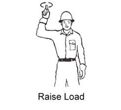
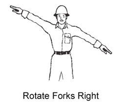
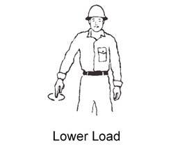
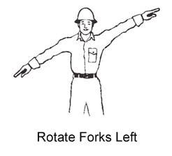
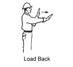
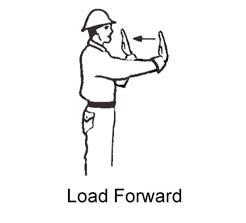
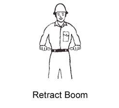
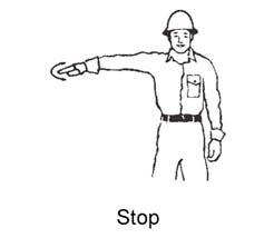
For safety, know and understand the traffic flow patterns of your jobsite and the Telescopic Handler hand signals. Use signal persons and make sure you can see the signal person and acknowledge the signals given. Refer to the safety hand signal illustrations on the next page. The backup alarm automatically sounds when the travel lever is in Reverse. Care should be taken when down shifting or reversing because damage to the transmission can occur if shifting is forced or attempted while traveling. When ramps must be used in transporting loads with the machine, the following shall be the minimum widths for safe travel:
Compacted dirt, gravel, etc. - 12 ft. (3.6 m) Woodboard, concrete, etc. - 10 ft. (3 m)
Permanent aisles, roadways, passageways, floors and ramps should be marked or defined in some fashion. Permanent or temporary protrusion of loads, equipment, material and construction facilities into the usual operating area should be guarded, clearly and distinctively marked, or clearly visible. Maintain a safe distance from the edge of ramps, platforms and other similar working surfaces. Controlled lighting of adequate intensity should be provided in operating areas. Where operating conditions indicate, the operator/user is responsible for having the machine equipped with lights. Provision should be made to prevent trucks, semi-trailers and railroad cars from being moved during loading and unloading. Wheel stops, parking brakes, or other positive means should be used to prevent movement during loading and unloading. DO NOT move railroad cars or trailers with the Telescopic Handler.


DO NOT use the boom and attachment for leverage to push the machine out of mud. IMPORTANT: DO NOT lower boom at high engine speed when attachment tool is at maximum rearward tilt. Damage to slave cylinders may result.
GENERAL LOAD HANDLING
NEVER attempt to work controls except from the operator’s seat. NEVER jerk or use fast movements. Avoid sudden stops, starts and changes in direction. Operation of the hydraulic system depends on engine speed and the distance the controls are moved. When operating these controls it is important to develop a technique called “feathering.” Feathering the control means starting the desired motion by moving the control a small amount away from neutral. Then, after movement has started, the control can be eased to full movement. Use the same feathering technique to stop the motion.
Load Capacity and Reach
The machine has flip-charts in the operator’s station that provide, at a glance, the capacity limits at various positions of attachment tool extension and elevation. A set of the load zone charts is reproduced at the end of this manual for reference.
A typical load zone chart is shown on this page. The scale on the left indicates height in feet above the ground level. The scale on the bottom shows the distance in feet from the front of the machine. The arc lines noted by the numbers “1” through “5” correspond
WARNING
Excessive speed can be hazardous. ALWAYS exercise caution and good judgement while operating the machine. The Mandatory Work Platform Safety Rules must be adhered to at all times while elevating personnel. ALWAYS maintain a safe distance from electric power lines and avoid contact with any electrically charged conductor and gas line. It is not necessary to make direct contact with a power line for power to ground through the structure of the machine. Keep the boom and load at least 10 ft. (3 m) from all power lines. Accidental contact or rupture can result in
electrocution or an explosion. Contact the “Call Before You Dig” referral system number at 8-1-1 in the U.S., or (888) 258-0808 in the U.S. and Canada, to locate any underground utility lines BEFORE starting to dig. Keep all body parts inside the operator’s station while operating the machine. BE SURE of clearance for the attachment tool when turning, working around buildings, etc. Turning corners too fast can tip the machine, or cause a load to tip off the attachment. Sudden slowing or stopping of the machine may cause the load to fall off the attachment tool. Be certain you can control both speed and direction before moving. Always place the machine in neutral and set the parking brake before raising or extending the boom. NEVER drive the machine up to someone standing in front of the load. NEVER leave the operator’s station without first lowering the attachment tool to the ground. Set the parking brake, place controls in neutral, shut off engine and remove the key. AVOID parking the machine on a slope, but if necessary, park across the slope and block the tires.
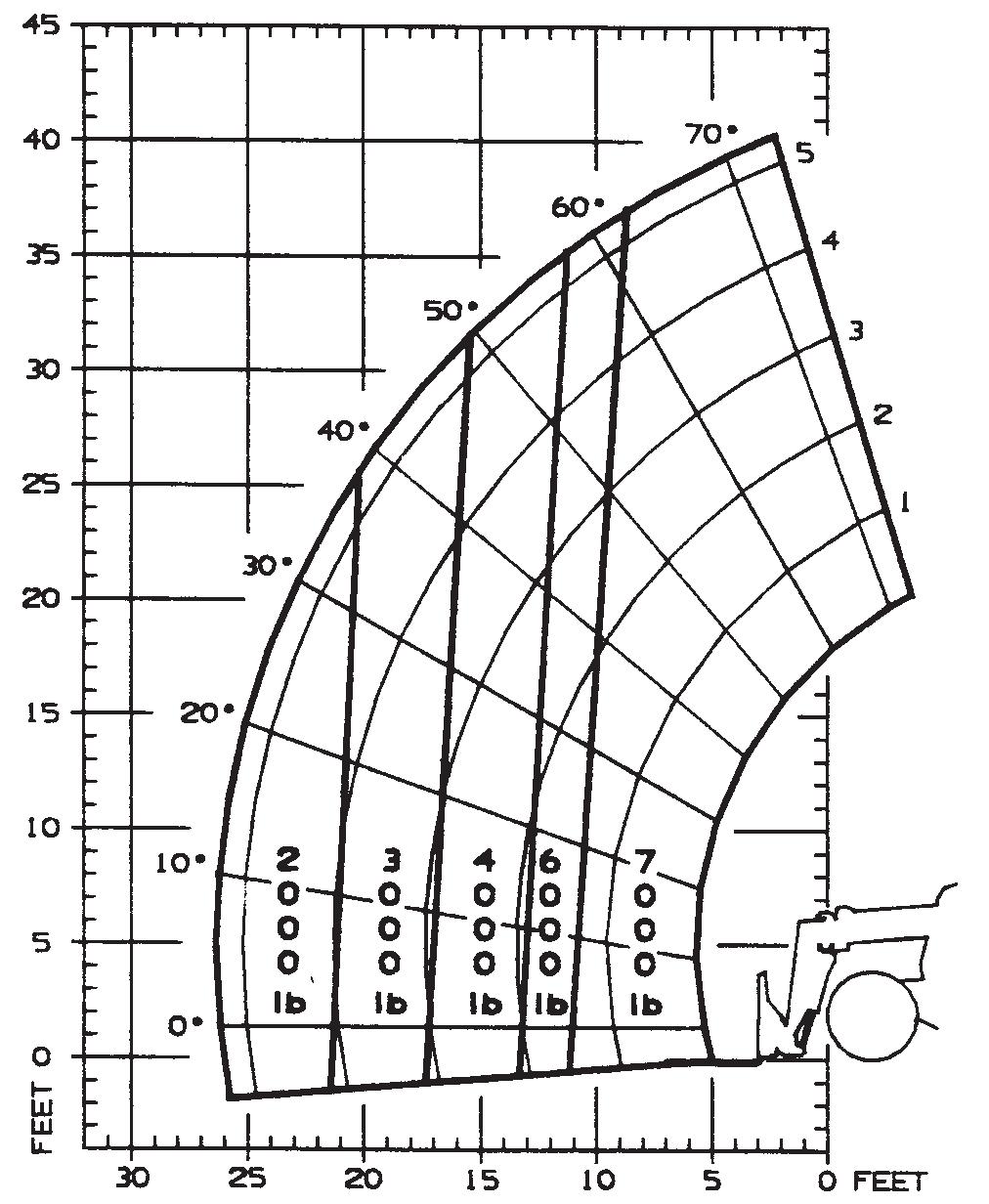
with the position extension markers on the operator side of the intermediate boom section.
The following example illustrates proper use of the load zone charts for the Telescopic Handler: Example: The operator, using a standard carriage attachment tool without outriggers, wants to raise a 3000 lb. load 20 feet high, and can only get to within 15 feet of the load placement point. Can this be done within the capacity of the machine? Analysis: See “Typical Load Zone Chart” above. Projecting up from the 15-foot reach mark on the horizontal axis to intersect a line through the 20-foot height mark on the vertical axis shows that up to a 4000 lb. load can be placed in that zone. During placement, the operator should observe when the arc reference number “4” on the boom is visible and stop. The operator knows the maximum safe extension distance with the 4000 lb. load has been reached.
LIFTING ATTACHMENT TOOL
HEIGHT ABOVE GROUND
BOOM EXTENSION MARKERS
DISTANCE LOAD IS EXTENDED
Typical Load Zone Chart APPLICATIONS
Picking Up the Load
Inspect the load before picking it up. If it appears unstable, DO NOT attempt to move it. DO NOT attempt lifting double-tiered loads, or straddling sideby-side pallets one on each fork. NEVER add extra unauthorized counterweights to the machine. Approach the load squarely and slowly with the
machine straight and level. Adjust the space between forks, if necessary. Engage the load equally on the forks until the load touches the carriage backrest. Tilt the forks back to position the load for travel.
WARNING
NEVER exceed the rated operating capacity of the Telescopic Handler as shown on the load zone charts.
Carrying the Load
If the load obstructs the view, have a helper direct the operator. Maintain ground speed consistent with ground conditions and which permit stopping in a safe
WARNING
Operating conditions such as slopes or soft ground can reduce the machine’s safe operating capacity. Exceeding the capacity when raising or extending the boom will cause the machine to tip forward.
manner.
Load Elevation and Placement
For ground level load placement, be sure the area under the load and around the machine is clear of equipment and personnel. Lower the load to the ground, tilt the forks to the horizontal position, and then carefully back away to disengage forks from the load.
For elevated or overhead placement, bring the machine
as close as possible to the landing point, and then: 1.Level the machine BEFORE raising the load. Use extreme caution for high placement. Be sure personnel are clear of the area where the load or the machine could tip or fall. 2.Set the parking brake, hold the service brake pedal in fully applied position and slowly raise the load, maintaining a slight rearward tilt to cradle the load. 3.As the load approaches the desired height, feather the boom control at minimum speed until the load is slightly higher than the landing point. 4.Continue the feathering technique and lower the load into place. 5.Free the forks from the load by alternately retracting and raising the boom. If this process is not possible, very slowly and carefully reverse the telescopic handler to free the forks from the load. 6.Lower the forks to travel height.
WARNING
NEVER travel with the boom above the carry position (attachment tool should be at minimum ground clearance). Boom should be fully retracted.
Use lower gears when traveling down an incline. NEVER coast with the transmission in neutral. Travel up and down grades slowly. DO NOT operate the machine on a slope or grade that exceeds 22% or 12o . Installing a Personnel Work Platform (PWP)
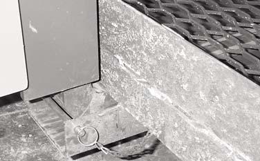
1.Center the forks on the carriage, spaced apart to match the distance required to engage the PWP. 2.After the forks are fully engaged in the PWP, secure the PWP to the forks. This can be accomplished by means of a retaining pin behind the heel of the forks as shown. 3.Secure the forks from pivoting upward in case the
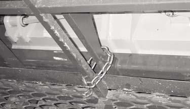
PWP is lowered onto an obstruction. This can be accomplished by using the chain supplied with the PWP, to secure the lower portion of the PWP to the bottom of the carriage, as shown. 4.On 40’ and 44’ models, connect the coiled wire from the remote shutdown switch to the connec-
WARNING
The machine must not be used to lift or carry personnel or be fitted with any form of personnel work platform unless fitted with the optional PWP System. If fitted with the PWP System, the Mandatory Work Platform Safety Rules (p. 13) must be followed at all times while lifting personnel.
Retaining Pin
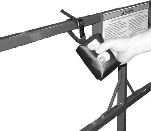
tor on the end of the boom. Secure the remote shutdown switch to the PWP using the strap attached to the switch, as shown below. 5.On the 55’ model, the remote shutdown switch is wireless-operated. Secure the remote shutdown
switch to the PWP using the strap attached to the switch, as shown. 6.Secure the lanyard from the body harness to the
PWP (or the boom). Each person in the PWP must have a body harness with a lanyard attached to the
PWP (or the boom).
Chain
WARNING
The PWP must meet ANSI/ITSDF B56.6-2005, Section 8.24. (See page 15 in the Safety chapter for PWP design requirements.) If the PWP being used does not offer means to secure the PWP to the forks and to secure the forks from pivoting, as shown in steps 2 and 3, then an alternate method must be used.
Electrical Connection
PWP Remote Shutdown Switch
Remote Shutdown Switch with Coiled Wire Connector on 40’ and 44’ Models Wireless Remote Shutdown Switch on 55’ Model
Lifting Personnel
The Telescopic Handler is primarily intended for use as a material handler. It should only be used to lift personnel if it is equipped with the (optional) PWP System when there is no other practical option. If this machine is to be used to lift personnel, then use only an approved work platform, lift personnel only with the PWP System activated, and follow the “Mandatory Work Platform Safety Rules” (Safety chapter p. 13). If the Telescopic Handler is equipped with a PWP System and is to be used for lifting personnel, the system must be activated, by the “PWP System” mode switch, which is located in the left switch bank. To activate the system, press the top of the PWP rocker switch, apply and hold the service brakes on for three or more seconds. The system is activated when the lamp in the PWP rocker switch is on continuously. When the PWP System is active: transmission is de-clutched into Neutral, parking brake is applied, rear axle stabilizer cylinder is locked, frame leveling speed is reduced,
PWP Remote Shutdown Switch
WARNING
ALWAYS check the PWP System for proper operation prior to use. (See page 54 for PWP System checking procedure.)
auxiliary hydraulic and carriage tilt and swing functions are disabled, machine inclination sensor is activated, with the result that the Telescopic Handler must be level laterally (side-to-side) and longitudinally (front-to-back) to the factory pre-set limits before the boom control joystick will function, and For 40’ and 44’ models, remote shutdown switch is activated, meaning that the switch must be connected and in the “on” position for the boom control joystick to function. Pressing the red button will disengage the boom control joystick, and stop all platform movement. The remote shutdown switch box is supplied with a coiled electrical cable, which must be connected to the outlet on the front of the innermost boom section near the carriage. The switch must be accessible to the platform personnel at all times when the platform is to be moved. For 55’ model, remote shutdown switch is activated, meaning that the switch must be “on” for the boom control joystick to function. Pressing the red button will disengage the boom control joystick and stop all platform movement. The remote shutdown switch box is a wireless remote control, so there is no direct connection to the
Telescopic Handler. The switch must be accessible to the platform personnel at all times when the platform is to be moved. To de-activate the PWP system, apply the service brakes and press the bottom of the PWP System rocker switch. The system is de-activated when the lamp in the PWP System rocker switch is off. NOTE: If the lamp in the PWP System rocker switch is flashing, apply the service brakes until the lamp goes off.
Stabilizer System
This is an additional safety function while elevating loads for placement. At a pre-determined boom angle, the stabilizer cylinder on the rear axle will lock up. When this happens, the parking brake activates and the frame leveling function slows down. Other than moving the boom and slowly leveling the frame, the machine will not be able to move until the boom is lowered below the pre-determined angle.
WARNING
In an emergency, if the platform worker has activated the remote shut-off switch and then is not able to re-activate the switch, such as if the worker fainted, then the Telescopic Handler operator is permitted to turn off the PWP System to regain control of the boom functions, in order to lower the work platform and come to the aid of the worker. But, understand this is only permitted in case of an emergency. Otherwise, the PWP System must be used at all timeswhen there are workers on the platform. This is the only exception!
WARNING
The machine becomes less stable as the load is raised higher. NEVER use frame leveling to position an elevated load. Always lower the load to the ground and reposition the machine.
If a hydraulic boom circuit hose should break with the boom up, shut down the machine. DO NOT attempt to bring down the boom or make repairs. Call your Manitou N.A. dealer immediately. As lift height increases, depth perception decreases. High elevation placement may require a signal person to guide the operator. DO NOT ram the lift cylinders to the end of the stroke. The resulting jolt could spill the load. A jib or a truss boom should ONLY be used to lift and place loads when the machine is stationary and the frame is level. Transporting suspended loads must ALWAYS be done slowly and cautiously, with the boom and load as low as possible. Use taglines to restrict loads from swinging, to avoid overturn. SUSPENDED LOADS
The handling of suspended loads by means of the truss boom or other similar device can introduce dynamic
forces affecting the stability of the machine that are not considered in the stability criteria of industry test standards. Grades and sudden starts, stops and turns can cause the load to swing and create a hazard.
Guidelines for “Free Rigging / Suspended Loads”
1.DO NOT exceed the rated capacity of the telehandler as equipped for handling suspended loads. The weight of the rigging must be included as part of the load. 2.During transport, DO NOT raise the load more than 12 inches (305)mm above the ground, or raise the boom more than 45º 3.Only lift the load vertically - NEVER drag it horizontally. 4.Use multiple pickup points on the load when possible. Use tag lines to restrain the load from swinging and rotating. 5.Start, travel, turn and stop SLOWLY, to prevent the load from swinging. DO NOT exceed walking speed. 6.Inspect rigging before use. Rigging must be in good condition and in the U.S. comply with
OSHA regulation §1910.184, “Slings,” or §1926.251, “Rigging equipment for material handling.” 7.Rigging equipment attached to the forks must be secured such thta it cannot move either sideways or fore and aft. load center must not exceed 24 inches (610 mm). 8.DO NOT lift the load with anyone on the load, rigging or lift equipment, and NEVER lift the load over personnel. 9.Beware of the wind, which can cause suspended loads to swing, even with taglines. 10.DO NOT attempt to use frame-leveling to compensate for load swing.
MATERIAL HANDLING BUCKET TOOL APPLICATION
IMPORTANT: The 55’ model is not intended for ground or material pile engagement. The bucket should be used for light-duty site cleanup only.
Material Densities
The table on this page lists densities for some common materials that could be carried in a Telescopic Handler bucket tool. The densities listed are average values and
Material Density in (lb/yd3)
Density in (kg/m3)
Ashes 945-1350 560-800 Brick-common 3024 1795 Cement 2970 1760 Charcoal 621 370 Clay 2160-2700 1280-1600
Coal 1431-1701 850-1010 Concrete 3105 1840 Cinders 1350 800 Coal-anthracite 2538 1505 Coke 810 480
Earth-dry loam 810 480 Earth-wet loam 1755 1040 Granite 2511-2997 1490-1780 Gravel-dry 1782 1060 Gravel-wet 2430 1440
Gypsum-crushed 3105 1840 Iron Ore 3915 2320 Lime 1620 960 Limestone 2430 1440
Manure-liquid 1755 1040 Manure-solid 1215 720 Peat-solid 1269 755 Phosphate-granular 2430 1440 Potash 1836 1090 Quartz-granular 2970 1760
Salt-dry 2700 1600 Salt-Rock-solid 3645 2160 Sand-dry 2916 1730 Sand-wet 3375 2000 Sand-foundry 2565 1520
Shale-crushed 2430 1440 Slag-crushed 1890 1120 Snow 405-1350 240-800 Sulpha 2565 1520 Taconite 2889 1715
intended only as a guide.
Digging and Loading
Refer to the illustration on the next page. Retract and lower the boom, then tilt the bucket’s cutting edge down into contact with the ground. Drive the bucket into the material. As the engine loads, roll the bucket back slowly and, at the same time, decrease travel speed. IMPORTANT: ALWAYS fully retract the boom before driving into material.
NOTE: When attempting to fill the bucket while working with most hard-packed materials, it will usually be necessary to raise the boom while rolling back the bucket.
Digging Loose Materials
Digging Hard-Packed Materials
Loading Bucket
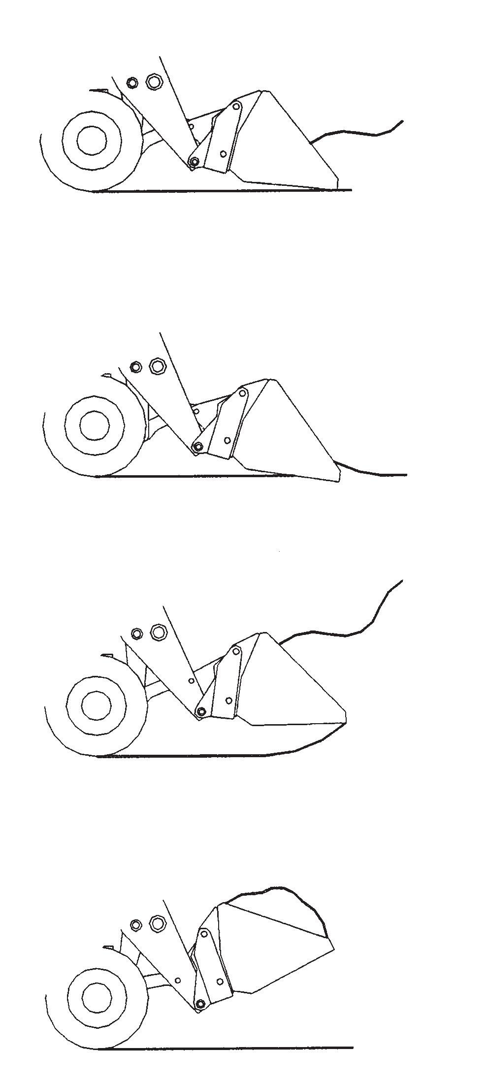
Carrying Load
Digging, Loading and Carrying Material
When the bucket is filled, back the machine away from the material and roll back the bucket before proceeding to the dumping area.
WARNING
DO NOT drive too close to an excavation or ditch. BE SURE the surrounding ground has adequate strength to support the weight of the machine and load.
Carry the loaded bucket as low as possible until reaching the pile. Slowly stop forward motion, then raise and extend the boom high enough so that the bucket clears the top of the pile. Then slowly move the machine ahead to position the bucket, and dump the material on top of the pile. Empty the bucket. Back the machine away while retracting and lowering the boom, and rolling back the bucket.
Dumping the Load into a Truck
Carry the loaded bucket low and approach the truck or trailer box, square with the side of the box. Stop as close to the side of the box as possible while still allowing clearance for raising and extending the boom. Raise and extend the boom until the bucket clears the top of the box, and slowly position the bucket over the inside of the box. Then tilt the bucket forward. After the material is dumped, slowly back away from the box, and then retract and lower the boom while rolling back the bucket.
Dumping the Load over an Embankment
Carry the loaded bucket as low as possible while slowly traveling toward the dumping area. Stop the machine at the position where the bucket extends halfway over the edge of the embankment. Then tilt the bucket forward, and raise and extend the boom to dump the material. After the material is dumped, slowly back away from the embankment while retracting and lowering the boom, and then rolling back the bucket.
WARNING
ALWAYS carry a loaded bucket as close to the ground as possible. For additional stability when operating on inclines, ALWAYS travel with bucket end of the machine toward the top of the incline.
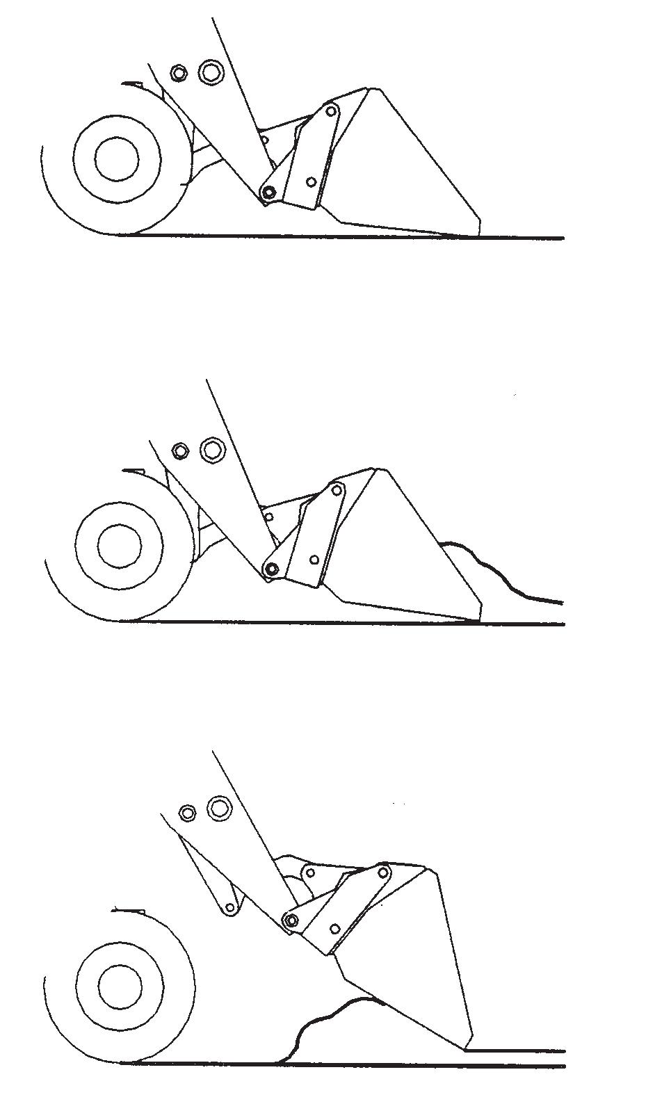
Scraping with a Bucket
Refer to the illustration on the next page. For scraping, the machine should be operated in the forward direction. First, position the boom retracted and down. Next tilt the bucket cutting edge forward at a slight angle. Then travel slowly forward. With the bucket in this position, material can flow over the cutting edge and collect inside the bucket.
Leveling with a Bucket
First, drive the machine to the outer edge of the area to be leveled. Then, with the boom retracted and down, tilt the bucket forward to place the bucket cutting edge at a 30 to 45 degree angle to the surface being leveled. Next, drive the machine rearward while feathering the boom control joystick, dragging the dirt and, at the
same time, leveling it.
Positioning Bucket for Scraping
Scraping with Bucket
Leveling with Bucket ving on public highways is prohibited, transport the machine using a vehicle of appropriate size and capacity.
TRANSPORTING BETWEEN JOBSITES
When transporting the Telescopic Handler, know the overall height to allow for clearance of obstructions. Remove or tape over the Slow-Moving Vehicle (SMV) emblem if it will be visible to traffic.
ALWAYS abide by the following recommended procedures and guidelines when using ramps to load the machine onto (or unload it from) a truck or trailer. Failure to heed can result in damage to equipment and serious personal injury or death! Tie-down slots are provided for inserting chains through to secure the machine while transporting.
Front Tie-Down Rear Tie-Down
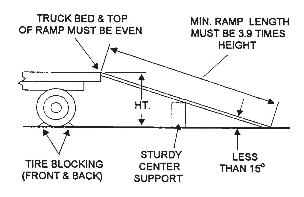
Loading Machine Using Ramps
NOTE: A matched pair of ramps is required.
TRUCK BED AND TOP OF RAMP MUST BE EVEN MINIMUM RAMP LENGTH MUST BE 3.9 TIMES HEIGHT
Scraping and Leveling with Bucket
ROAD TRAVEL
For short distance highway travel, attach a SlowMoving Vehicle (SMV) emblem (purchased locally) to the back of the Telescopic Handler. Activate the hazard lights on the machine. For highway operation, obtain and install an amber flashing beacon. NOTE: ALWAYS follow ALL state and local regulations regarding the operation of equipment on or across public highways. Whenever there is an appreciable distance between jobsites, or if dri-
TIRE BLOCKING (FRONT AND BACK) STURDY CENTER SUPPORT
LESS THAN 15°
Ramp Placement
1.The ramps MUST be of sufficient strength to support the machine. The use of strong steel ramps is recommended, as well as center supporting blocks. 2.The ramps MUST be firmly attached to the truck or trailer bed with NO step between the bed and the ramps.
3.The incline of the ramps MUST be less than 15 degrees (ramp length MUST be at least 16 feet (4.9 m) long). 4.Ramp width MUST be at least 1-1/2 times the tire width. 5.Block the front and rear of the tires on the truck or trailer. Engage the parking brake. 6.Position the machine (with the boom facing toward the front of the truck or trailer) so that it is straight in line with the ramps. 7.Slowly (at the lowest engine speed possible) and carefully drive the machine up the ramps. 8.Secure the machine to the bed of the truck or trailer. Tie-down slots are provided on the front and rear sides of the frame structure.
WARNING
NEVER adjust travel direction (even slightly) while traveling on the ramps. Instead, back down off the ramps, and then realign the machine with the ramps.
take as many of the following actions as possible to discourage theft, to aid in the recovery in the event that the machine is stolen, and to reduce vandalism: 1.Remove keys from unattended machines. 2.Attach, secure, and lock all anti-vandalism and anti-theft devices on the machine. 3.Lock doors of cabs when not in use. 4.Inspect the gates and fences of the vehicle storage yard. If possible, keep machines in well-lighted areas. Ask the local law enforcement agency to make frequent checks around the storage and work sites, especially at night, during weekends, and on holidays. 5.Report any theft to your dealer and insurance company. Provide the model and serial numbers.
Request that your dealer forward this information to Manitou N.A. Company.
WARNING
NEVER transport the machine with the boom raised or extended. BE SURE to secure the machine to the truck or trailer bed using chains and binders or steel cables, to prevent any movement while transporting.
Unloading Machine Using Ramps
NOTE: A matched pair of ramps is required.
Repeat steps 1 through 5 and proceed as follows to unload the machine:
6.Remove the tie-down chains/cables. 7.If necessary, adjust the machine so that the wheels are in line and centered with the ramps. 8.Slowly (at the lowest engine speed possible) and carefully drive the machine down the ramps.
THEFT DETERRENTS
Manitou N.A. Company has recorded all major component part numbers and serial numbers. Users should