34 minute read
8 Service and Storage


Chapter 8
SERVICE AND STORAGE
GENERAL INFORMATION
This Service and Storage chapter describes procedures to follow for making routine maintenance checks, adjustments and replacements. Most of the procedures are also referred to in the Maintenance chapter of this manual. For engine-related adjustments and servicing procedures, refer to the engine manual provided.
All service routines, with the exception of those described under the “Dealer Services” topic, are owner-operator responsibilities. All operator services described under the subtopics are also referred to on a decal located on the inside right side panel of the operator’s station. Refer to the Lubrication chapter of this manual for lubrication information.
WARNING
BEFORE performing any service on the Telescopic Handler, unless expressly instructed to the contrary, exercise the Mandatory Safety Shutdown Procedure(p. 8, Safety chapter). After service has been performed, BE SURE to restore all guards, shields and covers to their original positions before resuming machine operation.
PRECAUTIONS
DO NOT perform any maintenance or repair without the owner’s prior authorization. Allow only trained personnel to service the machine.
Warranty repairs can only be done by an authorized Manitou Americas dealer. Dealers know what portions of the machine are covered under the terms of the Manitou Americas Warranty and what portions are covered by other vendor warranties.
When a problem occurs, do not overlook simple causes, such as an empty fuel tank. Check for leaks and broken connections. Make note of any specific symptoms, noises, etc. and contact your local Manitou Americas dealer. IMPORTANT: Always dispose of waste lubricating oils, anti-freeze and hydraulic fluids according to local regulations or take them to a recycling center for disposal. DO NOT pour them onto the ground or into a drain.
DEALER SERVICES
The following areas of internal components service replacement and operating adjustments should only be by (or under the direction of) an authorized Manitou Americas Telescopic Handler dealer.
IMPORTANT: DO NOT service or repair major components, unless authorized to do so by your Manitou Americas dealer. Any unauthorized repair will void the warranty.
POWERTRAIN COMPONENTS
The engine and hydrostatic transmission are coupled directly to each other. All service routines related to the internal components are precise and critical to proper powertrain operation. The axle differential and planetary ends are sophisticated assemblies that require special know-how and tools for servicing.
IMPORTANT: If any powertrain components are suspected of faulty operation, contact your Manitou Americas dealer for assistance.
HYDRAULIC SYSTEM COMPONENTS
Valves, pumps, motors and cylinders are sophisticated assemblies, which require special know-how and tools for servicing. All cylinders are appropriately designed with particular strokes, diameters, checks and hose connection provisions unique to the machine application requirements. A schematic (Maintenance chapter) can be used as a guide for service reference, as required.
Internal service on any of these components should only be performed by (or under the direction of) an authorized Manitou Americas Telescopic Handler dealer.
WARNING
Tilt, lift, and extend cylinders have counterbalance valves. These valves keep hydraulic fluid from entering and exiting the cylinders while they are not being activated, and they are under extremely high pressure. Before removing one of these valves, you ARE REQUIRED to call your Manitou Americas dealer or Manitou Americas Service Department. Failure to do so may result in serious injury or death.
An electrical system schematic is provided, which includes instrumentation, electrical components and switch connections. It is located at the back of this manual and can be used as a guide for service reference, as required.
OPERATOR SERVICES
Some of the operator-related services will require access to components located inside the superstructure, under shields, hoods and covers. The chart on this page notes the components accessed in each particular area.
ACCESS TO COMPONENTS CHART
Component Operator’s Frame Front FrameFront EngineRear Engine Station Cover Cover Cover
Axle (underside) Engine Hydrostatic Transmission Drive Shaft (underside) Main Control Valve (center) Muffler (rear) Air Cleaner (front) Battery (front) Radiator l
Brake Valve (center) Travel Controls (steer column) l Boom Controls (right inside) l Hydraulic Test Ports Hourmeter (dash) l
Switches/Indicators (dash) l
Hydraulic Pump (front) Hydraulic Filter Misc. Hydraulic Valves Heater (lower dash area) l
Fuse and Relay Panel l l
l l l l
l
l l l l
l
l l
l
l
WARNING
DO NOT smoke or allow any open flames in the area while checking or servicing hydraulic, battery or fuel systems; all contain highly flammable liquids or explosive gases, which can cause an explosion or fire if ignited. Wear a face shield when you disassemble spring-loaded components or work with battery acid. Wear a helmet or goggles with special lenses when you weld or cut with a torch. When working beneath a raised machine, always use blocks, jack-stands or other rigid and stable supports. Wear appropriate protective clothing, gloves, and shoes. Keep feet, clothing, hands and hair away from moving parts. Always wear safety glasses or goggles for eye protection from electric arcs from shorts, fluids under pressure, and flying debris or loose material when the engine is running or tools are used for grinding or pounding. NEVER weld on bucket, forks, boom, support frame or ROPS/FOPS without the consent of the manufacturer. These components may be made with metals that require special welding techniques, or with designs that do not allow weld repairs. NEVER cut or weld on fuel lines or tanks.
If repair welding is ever required, BE SURE to attach the ground (-) cable from the welder as close as possible to the area to be repaired. Also, remove battery positive (+) terminal connection before welding.
Choose a clean, level work area. Make sure you have sufficient room, clearances, and adequate ventilation. Clean the walking and working surfaces. Remove oil, grease and water to eliminate slippery areas. Utilize sand or oil absorbing compound, as necessary, while servicing the Telescopic Handler.
Before starting inspection and repair, move the machine onto a level surface, shut down engine and remove the ignition key, and release all hydraulic pressure. Always block the boom securely, or lower it to full ground contact. Place all controls in neutral. Block the tires. Remove the ignition key. Remove only guards or covers that provide needed access. Wipe away excess grease and oil.
Excessively worn or damaged parts can fail and cause injury or death. Replace any cracked or damaged parts. Use only genuine Manitou Americas parts for service.
Use care not to damage machined and polished surfaces. Clean or replace all damaged or painted-over plates and decals that cannot be read.
After servicing, check the work performed, that no parts are left over, etc. Install all guards and covers.
WARNING
NEVER leave guards off or access doors open when the machine is unattended. Keep bystanders away if access doors are open.
Service Every 10 Hours or Daily
WARNING
Static electricity can produce dangerous sparks at the fuel-filling nozzle. Do not wear polyester, or polyester-blend clothing while fueling. Before fueling, touch the metal surface of the machine away from the fuel fill to dissipate any built-up static electricity. Do not re-enter the machine but stay near the fuel filling point during refueling to minimize the build-up of static electricity. Do not use cell phones while fueling. Make sure the static line is connected from the machine to the fuel truck before fueling begins.
Ultra-Low Sulfur Diesel (ULSD) poses a greater static ignition hazard than earlier diesel formulations. Avoid death or serious injury from fire or explosion; consult with your fuel or fuel system supplier to ensure the entire fuel delivery system is in compliance with fueling standards for proper grounding and bonding practices.
After operation each day, the fuel tank should be filled to prevent water from condensing in the tank. To fill, remove the filler cap and add fuel.
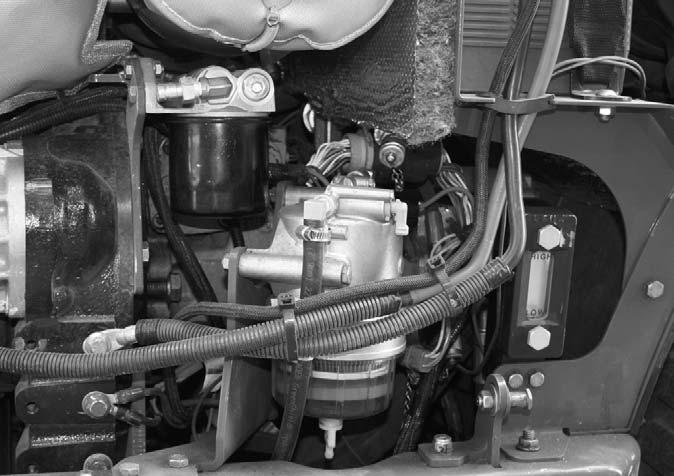
CHECKING FUEL FILTER/WATER SEPARATOR
Visually check the fuel filter/water separator for water and deris. Drain the filter/separator if water is present following the draining procedure in the 50 hour service interval.
Fuel Filter/Water Separator
IMPORTANT
Water in the fuel system can cause severe engine damage. Drain water from the fuel filter/water separator anytime water is present.
CHECKING ENGINE OIL LEVEL
With the machine on level ground, and the engine stopped for ten minutes or more, open the right side engine cover and remove the engine dipstick. Wipe it clean, re-insert it and remove to obtain a reading. If the oil level is down, or below the ADD mark, fill with the required amount of oil to bring the level to the FULL mark. See the Lubrication chapter for the type of oil to use.
CHECKING COOLANT LEVEL
Check the coolant level before starting the machine the first time every day. With the machine on level ground, open the engine cover. Check that the coolant in the coolant expansion tank is between the Full and Add marks on the tank. If the coolant is below the Add mark on the tank, remove the cap and add a low-silicate ethylene glycol based coolant mixed with quality water and supplemental coolant additives (SCAs) suitable for heavyduty diesel engines to the coolant expansion tank. See the engine manual for additional information. Replace the cap securely.
Engine Oil Dipstick
WARNING
DO NOT remove the radiator cap when the engine is running hot or overheated. Coolant is extremely hot and under pressure and it can burn your skin.
NOTE: The coolant system is designed for coolant top-off only through the expansion tank. Do not add coolant directly to the radiator.
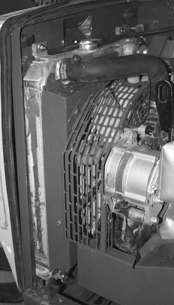
CHECKING RADIATOR FOR DEBRIS
With the machine on level ground, open the engine cover. Remove the rear radiator cover by turning the two quarter turn latches counter-clockwise. Remove the cover by lifting up and to the rear. If necessary, clean the radiator fins of debris by blowing compressed air or water through the radiator fins from either side of the radiator.
It may be best to clean as much as possible by blowing from the inside of the radiator first, then blowing from the outside of the radiator until the air or water is free of dirt and debris.
IMPORTANT: Use caution when cleaning the radiator. High pressure air or water may bend radiator fins which will reduce the radiator cooling capacity.
The machine must be on level ground with boom lowered and completely retracted. The fluid MUST be cool when checking the reservoir level, to reduce the possibility of overfilling the hydraulic system.
Open the right side engine cover and locate the sight gauge below the battery compartment. The oil level should be at the midpoint of the sight gauge. If the oil level is down, or below the sight gauge, fill with the required amount of oil. See the Lubrication chapter for the type of oil to use.
Hydraulic Oil Sight Gauge
IMPORTANT: Be careful when removing the reservoir filler cap so that no dirt or other foreign matter enters the hydraulic system. DO NOT OVERFILL.
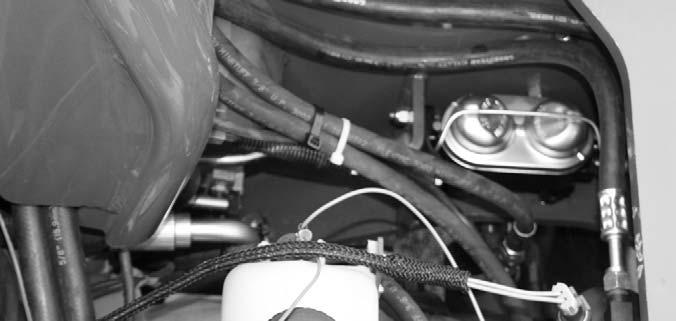
CHECKING BRAKE RESERVOIR LEVEL
Remove the cover on the front of the frame. Remove the reservoir cover to check the fluid level. If low, fill to the proper level with the correct fluid. See the Lubrication chapter for the type of fluid to use.
Brake Fluid Reservoir
CHECKING TIRE PRESSURES
To ensure proper operating stability and extend tire life, proper and equal tire pressure should be maintained in all four tires. Check tire pressures “cold.” 12-16.5 NHS 10 PR: 65 psi (450 kPa)
NOTE: If the tires have been filled with water or calcium chloride for ballast, a calcium chloride tire pressure gauge MUST be used to check the tire pressure.
To ensure proper load carrying capability, original equipment tires comply with the specifications published in the Tire and Rim Association Yearbook. Replacement tires MUST meet the same specifications. When replacing tires, be sure all tires are of the same type, quality and load rating, and the same size as the original equipment. When removing tires, follow industry safety practices. Deflate completely prior to removal. After assembly of the tire on the rim, use a safety cage or restraining device while inflating.
WARNING
Inflating or servicing tires can be dangerous. Whenever possible, trained personnel should service and mount tires. To avoid possible death or serious injury, follow the safety precautions below: 1.BE SURE the rim is clean and free of rust. 2.Lubricate both the tire beads and rim flanges with a soap solution. DO NOT use oil or grease. 3.DO NOT place your fingers on the tire bead or rim during inflation. Use a clip-on tire chuck with a remote hose and gauge, which allows you to stand clear of the tire while inflating it. 4. NEVER inflate beyond 35 psi (240 kPa) to seat the beads. If the beads have not seated by the time the pressure reaches 35 psi (240 kPa), deflate the assembly, reposition the tire on the rim, relubricate both parts and re-inflate. Inflation pressure beyond 35 psi (240 kPa) with unseated beads may break the bead or rim with explosive force sufficient to cause death or serious injury. 5.After seating the beads, adjust the inflation pressure to the recommended operating pressure listed. 6.DO NOT weld, braze, or otherwise attempt to repair and use a damaged rim.
On new machines, or any time a wheel has been removed, re-torque until 450 ft.-lbs. (610 Nm) is maintained.
CHECKING INSTRUMENTS OPERATION
Allow the engine to warm up for about five minutes before beginning operation. Indicator lamps should be OFF and gauges in the multi-function display should register normal readings.
CHECKING GENERAL MACHINE OPERATION AND CONDITION
Are any decals missing or damaged? Are all guards, shields and covers in place? Do all controls function smoothly and properly? Are there any abnormal vibrations or noises? Are any hose or fitting connections leaking? Is the engine exhaust color normal?
Service Every 50 Hours or Weekly
LUBRICATING GREASE POINTS
Refer to the Lubrication chapter of this manual for weekly grease fitting locations and other related details.
DRAINING FUEL FILTER/WATER SEPARATOR
IMPORTANT
Water in the fuel system can cause severe engine damage. Drain water from the fuel filter/water separator anytime water is present.
Fuel Shutoff Valve The semi-transparent seperator cup contains a red float ring. The float ring will rise to the surface of the water to show how much water needs to be drained.
1.Place a suitable container under the water separator to catch drained water. 2.Close the fuel shutoff valve located on the fuel filter head by rotating it 1/4 turn clock-wise to the horizontal position. 3.Loosen the drain screw at the bottom of the fuel filter/water seperator to drain the acumulated water. 4.Tighten the drain screw and open the fuel shutoff valve. 5.Prime the fuel system by turning the ignition key
ON for 10 -15 seconds. The following initial oil and filter changes should be made on a new machine:
New Machine Service
1.Change the engine oil and filter after the first 50 hours of use. 2.Change the hydraulic return filter element after the first 100 hours of use. Thereafter these changes should be made at the regular maintenance schedule listed below. Refer to those schedules for the necessary procedures.
Engine Oil and Filter (250 Hours) Hydraulic Return Filter Element (500 Hours)
Perform all other service requirements up to this point, as well as the following:
Service Every 250 Hours or Quarterly
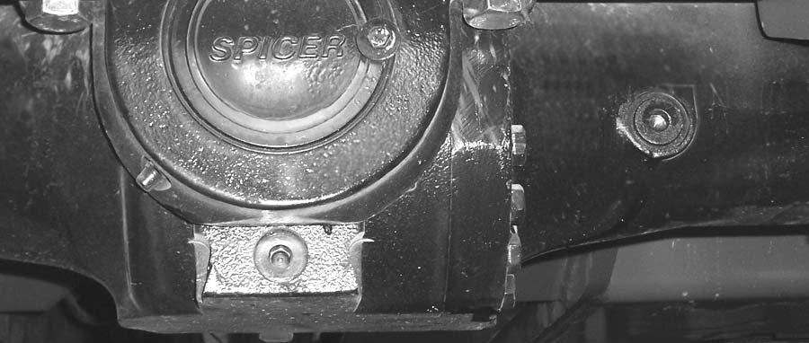
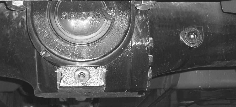
CHECKING AXLE OIL LEVELS
Differential
NOTE: The Telescopic Handler should be on a level surface for this procedure.
Fuel Drain Screw
Drain the fuel filter/water seperator anytime water or other contaminants are present.
Drain Plug Check / Fill Plug
Remove the oil check/fill plug. See illustration. Oil should flow from the hole. If low, add oil until it flows from the hole. Replace the plug, wait 10 to 15 minutes and repeat the fill procedure. Continue this process until the differential is full. Refer to the Lubrication chapter for the proper oil specification. Replace the check/fill plug.
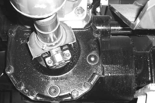
Front Axle Transfer Case
NOTE: The Telescopic Handler should be on a level surface for this procedure.
Check / Fill Plug
Drain Plug Change the engine oil and filter using the following procedure:
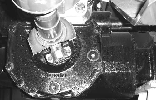
1.With the engine warm, open the cover under the engine to access the drain plug. Remove the crankcase drain plug.
Engine Oil Filter
Engine Oil Drain Plug
Remove the oil check/fill plug. See illustration. Oil should flow from the hole. If low, add oil until it flows from the hole. Replace the plug, wait 10 to 15 minutes and repeat the fill procedure. Continue this process until the differential is full. Refer to the Lubrication chapter for the proper oil specification. Replace the check/fill plug.
Planetary Hubs
NOTE: The planetary hubs can be checked without jacking up the machine.
Plug in fill and check position.
The planetary hubs have one plug each used for filling and draining. Refer to illustration above. For checking the level and filling, position the wheel until the oil level arrow is horizontal. Remove the plug. If oil does not run out, add oil until it overflows. Check the remaining hubs the same way. Refer to the oil specifications in the Lubrication chapter of this manual. IMPORTANT: DO NOT discharge oil onto ground. Catch and dispose of per local waste disposal regulations.
2.The engine oil filter should be changed at every oil change interval. Remove and discard the disposable filter. Wipe the gasket sealing area of the filter head mounting surface with a clean cloth. IMPORTANT: Use only genuine OEM engine replacement filters.
3.Apply a thin coat of clean oil to the new oil filter gasket. Hand tighten. Refill the crankcase with new oil. Follow specifications in the Lubrication chapter for type and viscosity of new oil. 4.After new oil has been added, run the engine at idle speed until the oil pressure lamp is OFF. Check for leaks at the filter and drain plug. Re-tighten only as much as necessary to eliminate leakage.
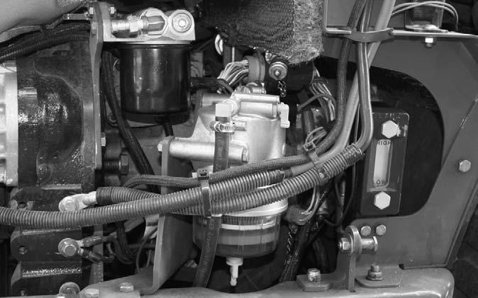
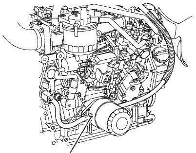
CHANGING FUEL FILTERS
WARNING
NEVER service the fuel system while smoking, while near an open flame, or after the engine has been operated and is hot.
This machine is equipped with a fuel filter/water separator and fuel filter. See the illustration for filter locations.
Fuel Filter/Water Seperator
Replacing the Fuel Filter
1.Stop the engine and allow it to cool. 2.Close the fuel shutoff valve on the fuel filter/water seperator. 3.Using a filter wrench, remove the fuel filter by turning it to the left. When removing the filter, take care to prevent spilling any fuel in the filter element. 4.Clean the filter sealing surface on the filter body.
Apply a small amount of fuel on the gasket of the new filter element. 5.Install the new filter by turning it to the right until it comes in contact with the mounting surface.
Then using the filter wrench, tighten the filter one additional turn. 6.Open the fuel shutoff valve of the fuel filter/water seperator. 7.Prime the fuel system by turning the ignition key
ON for 10 -15 seconds.
Replacing the Fuel Filter/Water Seperator
1.Place a suitable container under the fuel filter/water separator to catch any fuel. 2.Close the fuel shutoff valve located on the fuel filter head by rotating it 1/4 turn clock-wise to the horizontal position. 3.Loosen the drain screw at the bottom of the fuel filter/water seperator and drain the fuel 4.Turn the seperator cup to the left and carefully remove the cup. 5.Remove the float ring from the cup. Pour the fuel and contaminants into a suitable container for disposal. Clean the inside of the cup. 6.Remove the old filter element from the filter body and install the new filter element. 7.Position the float ring in the seperator cup. 8.Install the seperator cup to the filter body by tightening the cup to the right. 9.Close the drain screw and open the fuel shutoff valve. 10. Prime the fuel system by turning the ignition key
ON for 10 -15 seconds.
Priming the Fuel System
If the engine runs out of fuel or maintenance on the fuel system has been performed, the fuel system will need to be primed. Refer to the following fuel priming procedure. Refer to the engine manual for additional fuel priming procedures.
WARNING
Escaping diesel fuel under pressure can have sufficient force to penetrate the skin. Before applying pressure to the fuel system, BE SURE all connections are tight and lines and hoses are not damaged. Use a piece of wood or cardboard to search for suspected leaks. If injured by escaping fuel, see a doctor familiar with this type of injury at once or gangrene may result.
1.Turn the ignition key to the “ON” position for 15 seconds. This will allow the electic fuel pump to prime the fuel system. 2.NEVER use the starter motor to crank the engine in order to prime the fuel system. This may cause the starter motor to overheat and damage the coils, pinion and / or ring gear. NOTE: Only an authorized engine dealer can perform warranty service on the engine.
CHECKING THE BATTERY
The battery furnished in the machine is a 12-volt, wetcell battery.
Handling Battery Safely
The top of the battery must always be kept clean. Clean the battery with a brush dipped in an alkaline solution (ammonia or baking soda and water). After the foaming has stopped, flush the top of the battery with clean water. If the terminals and cable connection clamps are corroded or have a buildup, disconnect the cables and
WARNING
Explosive gas is produced while a battery is in use or being charged. Keep flames or sparks away from the battery area. Make sure battery is charged in a well-ventilated area. NEVER lay a metal object on top of a battery, because a short circuit can result.
Battery acid is harmful on contact with skin and fabrics. If acid spills, follow these first-aid tips: 1.IMMEDIATELY remove any clothing on which acid spills. 2.If acid contacts the skin, rinse the affected area with running water for 10 to 15 minutes.
3.If acid comes in contact with the eyes, flood the eyes with running water for 10 to 15 minutes. See a doctor at once. NEVER use any medication or eye drops unless prescribed by a doctor. 4.To neutralize acid spilled on the floor, use one of the following mixtures: a.1 pound (0.5 kg) of baking soda in 4 quarts (4 liters) of water. b.1 pint (0.4 liters) of household ammonia in 4 quarts (4 liters) of water. Whenever battery is removed from the unit, BE SURE to disconnect the negative (-) battery terminal connection first.
Jump Starting
If the battery becomes discharged or does not have enough power to start the engine, use jumper cables and the following procedure to jump-start the engine.
IMPORTANT: BE SURE that the jumper battery is also a 12-volt D. C. battery, and the vehicle used for jump starting has a negative-ground electrical system.
WARNING
The ONLY safe method for jump-starting a disharged battery is for TWO PEOPLE to perform the following procedure. The second person is needed for removing the jumper cables so that the operator does not have to leave the operator’s compartment while the engine is running. NEVER connect the jumper cables directly to the starter solenoid of either engine. DO NOT start the engine from any position other than the operator’s seat, and then ONLY after making sure all controls are in “neutral.”
Closely follow the jump-start procedures, in the order listed, to avoid personal injury. In addition, wear safety glasses to protect your eyes, and avoid leaning over the batteries while jump-starting.
DO NOT attempt to jump-start the machine if the battery is frozen, because this may cause it to rupture or explode.
1.Turn the key switches on both vehicles to “OFF.”
Be sure that both vehicles are in “Neutral” and
NOT touching. 2.Connect one end of the positive (+) jumper cable to the positive (+) battery terminal on the disabled machine first. DO NOT allow the positive (+) jumper cable clamps to touch any metal other than the positive (+) battery terminals. Connect the other end of the positive jumper cable to the jumper battery positive (+) terminal. 3.Connect one end of the negative (-) jumper cable to the jumper battery negative (-) terminal. 4.Make the final negative (-) jumper cable connection to the disabled machine’s engine block or frame (ground) − NOT to the disabled battery negative post. If making the connection to the engine, keep the jumper clamp away from the battery, fuel lines, and moving parts. NOTE: Twist the jumper cable clamps on the battery terminals to ensure a good electrical connection.
5.Proceed to start the machine. If it does not start immediately, start the jumper vehicle engine to avoid excessive drain on the booster battery.
6.After the machine is started and running smoothly, have the second person remove the jumper cables (negative (-) jumper cable first) from the jumper vehicle battery, and then from the disabled machine, while ensuring NOT to short the two cables together. Allow sufficient time for the alternator to build up a charge in the battery before operating the machine or shutting off the engine.
NOTE: If the battery frequently becomes discharged, have the battery checked for possible dead cells, or troubleshoot the electrical system for possible short circuits or damaged wire insulation.
CHECKING BOOM SLIDE PADS WEAR AND CLEARANCE
The boom is equipped with special nylon low friction slide pads between the telescopic sections. (See illustration.) These are pre-greased and initially worn-in at the factory. Normally greasing is not required, except for maintaining a light film of grease on the pad tracking areas of the boom sections. An exception would be if a boom section has been replaced.
Visually check for loose pad bolts. The bolts are torqued to 30 ft.-lbs. (40 Nm). If the bolts are retorqued at any time, Loctite® 271 (red) thread lock must be re-applied to the bolts.
If the boom starts to chatter under load, grease the slide pads and wipe off the excess grease. Maintain a clearance of 1/16” between the top or side slide pads and the
Shim
Front Outer
Pad
Spacer Plate Shim Pad boom. Shims can be added to achieve the proper clearance. Loosen the bolts and insert shims until proper clearance is obtained.
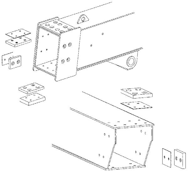
NOTE: When inserting shims in the side slide pads, be sure to place equal shims on both sides of the boom for even distribution of clearance.
Re-apply Loctite® thread lock to the bolts and retorque to 30 ft.-lbs. (40 Nm). Bottom slide pads should not be shimmed and should be replaced when the thickness is worn down to 3/8” (9.5 mm).
WARNING
Failure to maintain proper slide pad clearance and thickness could cause damage to the boom and result in sudden boom failure.
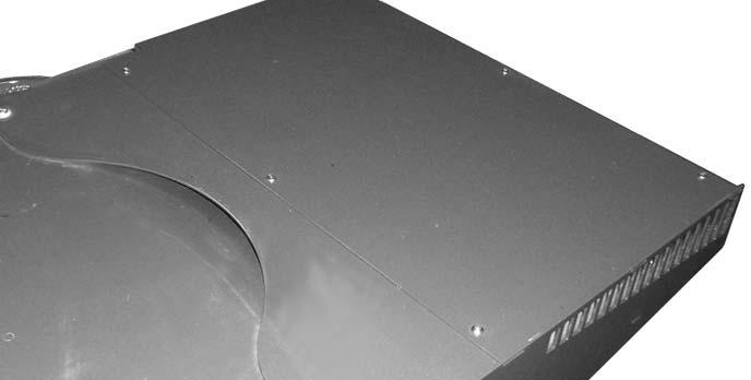
CLEAN AIR CONDITIONING CONDENSER
NOTE: Clean the condenser more often if there is a noticeable decrease in A/C performance.
IMPORTANT: Do not use a water jet or high-pressure steam, because this could damage the fins.
1.Remove the six screws (1) from the top cover of the condenser.
2. Remove the cover to gain access to the condenser (2).
1
Rear Inner
Slide Pad Detail
2
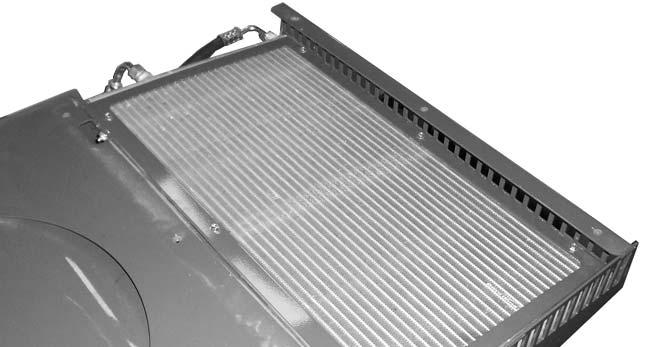
Top View of Condenser Assembly
3.Clean any large debris that may have collect on the top side of the condenser. 4.Clean the condenser use a jet of compressed air aimed in the same direction as the air flow.
NOTE: To aid in the cleaning process, carry out this operation with the condenser fans running.
5.Re-install the top cover.
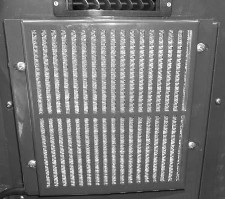
CLEAN/CHANGE CAB VENTILATION FILTER
NOTE: Clean or change the filter more often if there is a noticeable decrease in air flow from the air vents.
1.Remove the four screws (1) from the filter protective cover located on the lower portion of the dash in front of the brake pedal.
2. Remove the filter from the cover.
3.Clean the filter with a jet of compressed air. 4.Check the condition of the filter and replace it if necessary. 5.Install the filter in the protective cover, then reinstall the protective cover.
Perform all other service requirements up to this point, as well as the following: This spin-on type hydraulic filter element is located under the engine cover behind the radiator. Open the engine cover to access the hydraulic filter. Initial replacement is after the first 100 hours. The hydraulic filter element should be replaced every 500 hours or anytime the indicator on the multi-function display stays lit. Replace the filter using the following the procedure:
1.Turn off the engine. 2.Place a suitable container under the filter to catch any spilled oil. 3.Spin off the old hydraulic filter element. 3.Wipe the gasket sealing surface of the filter head with a clean cloth. 4.Apply a thin coat of clean oil to the new filter gasket. 5.Spin on the new filter element and hand tighten. 6.Run the engine at full throttle and check for leaks at the filter sealing area.
Perform all other service requirements up to this point, as well as the following:
Hydraulic Filter
1
Service Every 500 Hours or Half Year
WARNING
Before servicing the hydraulic filter, lower the boom to the ground. Service Every 1000 Hours or Yearly
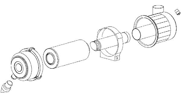
CHECKING AND CHANGING AIR FILTER ELEMENTS
IMPORTANT: Failure to follow proper filter servicing instructions could result in catastrophic engine damage.
The air cleaner assembly consists of an outer (primary) filter element and an inner (secondary) filter element.
The outer element should be replaced anytime the restriction indicator stays lit. The inner element should be replaced every third time the outer element is replaced, unless the outer element is damaged or the inner element is visibly dirty. Along with a daily check of the restriction indicator, check that the air cleaner intake hose and clamps, and the mounting bracket hardware are properly secure. Replace the filter following the procedure on this page:
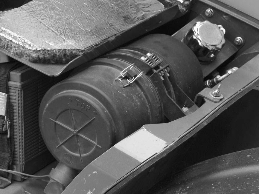
1.In order to gain access to the latches and clearance to remove the filter elements, remove the wing nut retaining the air cleaner in its mounting position. 2.Unlatch the three latches on the air cleaner and remove the cover. Clean out any dirt in the cover assembly.
3.Carefully pull the outer element out of the housing.
Never remove the inner element unless it is to be replaced. 4.Clean out any dirt in the housing. Leave the inner element installed during this step to prevent debris from entering the engine intake manifold.
Element Cover Mounting Band
Dust Ejector Primary Element Secondary Element
Air Cleaner Assembly
Air Cleaner Latch 5.Use a trouble light inside the new outer element to inspect for bad spots, pinholes and ruptures. IMPORTANT: NEVER use an element that is damaged. Severe engine wear and eventual failure can result if dirt gets through a hole in the element. Cleaning the outer element is not recommended.
NOTE: Replace the inner element only if it is visibly dirty or if the outer element has been replaced three times.
Before removing the inner element from the housing, clean out any dirt build up in the housing. Leave the inner element installed during this step to prevent debris from entering the engine intake manifold. Remove the inner element.
6.Check the inside of the housing for any damage that may interfere with the elements. 7.Be sure that the element sealing surfaces are clean. 8.Insert the element(s), making sure that they are seated properly. 9.Secure the cover to the housing with the three clamps. 10.Check the hose connections and make sure they are all clamped and tightened properly. 10.Re-position the air cleaner in its mounting position and re-install the wing nut.
CHANGING AXLE DIFFERENTIAL AND PLANETARY OIL
Differentials
1.Remove the check/fill plug. Remove the drain plug and drain out the old oil. Replace the drain plug (see illustration).
Check / Fill Plug
Wing Nut
Drain Plug
IMPORTANT: DO NOT discharge oil onto ground. Catch and dispose of per local waste disposal regulations.
2.Fill the differential with oil as specified in the
Lubrication chapter. When the oil flows from the check hole, replace the plug. Wait 10 to 15 minutes and repeat this process until the axle is full. Repeat this procedure with the other axle.
Front Axle Transfer Case
1.Remove the check/fill plug. Remove the drain plug and drain out the old oil. Replace the drain plug (see illustration).
Check / Fill Plug
Drain Plug
IMPORTANT: DO NOT discharge oil onto ground. Catch and dispose of per local waste disposal regulations.
2.Fill the transfer case with oil as specified in the
Lubrication chapter. When the oil flows from the check hole, replace the plug. Wait 10 to 15 minutes and repeat this process until the transfer case is full.
Axle Planetary Hubs
The hubs have one plug each used for draining and filling (see illustration).
1.Position the wheel until the oil level arrow points down. Remove the plug and allow the oil to drain out. Replace the plug.
Plug in drain position.
IMPORTANT: DO NOT discharge oil onto ground. Catch and dispose of per local waste disposal regulations.
2.Re-position the hub so the oil level arrow is horizontal. Fill with clean oil as specified in the Lubrication chapter. When the oil runs out, install
Plug in fill and check position.
CHANGING HYDRAULIC RESERVOIR OIL
Clean all dirt and debris from around the drain plug area.
1.Remove the drain plug and drain out all used oil.
Wash or blow off all collected particles from the magnetic drain plug. IMPORTANT: Do NOT discharge oil onto ground. Catch and dispose of per local waste disposal regulations.
2.Flush out the bottom of the tank with clean hydraulic oil. Re-install the drain plug. 3.Fill the tank with fresh oil. Follow specifications found in Lubrication chapter of this manual.
WARNING
Escaping hydraulic oil under pressure can have sufficient force to penetrate the skin. Before applying pressure to the hydraulic system, be sure all connections are tight and lines and hoses are not damaged. Use a piece of wood or cardboard to search for suspected leaks. If injured by escaping hydraulic oil, see a doctor familiar with this type of injury at once or gangrene may result.
IMPORTANT: Hydraulic fluid and filters should be replaced any time contamination is present before the normally scheduled change.
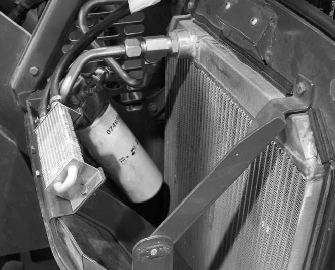
CHANGING RADIATOR COOLANT
Drain, flush and refill the cooling system as follows:
IMPORTANT: DO NOT discharge coolant onto ground. Catch and dispose of per local waste disposal regulations.
WARNING
Remove the radiator cap only when the engine is cool, or painful burns could result.
1.Remove the engine belly pan. 2.Loosen the radiator cap to its stop. This will release any sys- Radiator Cap tem pressure.
Remove the cap when all pressure is bled off. 3.Attach a 3/8” hose to the drain cock and route it through the belly pan opening to Drain Cock a collection container positioned below the radiator. 4.Loosen the radiator drain cock to drain the radiator. 5.Remove the coolant hose from the engine oil cooler to allow coolant to drain from the engine block. 6.When all coolant is drained, flush the system with clean fresh water to remove any rust, scale and contaminants. Allow the radiator and engine block to drain completely. 7.Replace all drain plugs and tighten the radiator drain cock. Clean the cooling fins in the radiator with compressed air or water pressure.
Oil Cooler Coolant Hose IMPORTANT: Fill the cooling system with a lowsilicate ethylene glycol based coolant mixed with quality water and supplemental coolant additives (SCAs) suitable for heavy-duty diesel engines. See the engine manual for additional information.
8.Pour the coolant slowly into the radiator until the coolant is at the bottom of the filler neck. Remove the cap of the expansion tank and add coolant to the full mark. 9.Inspect the radiator cap seal before installing it.
Replace it if it appears to be damaged. 10.Run the engine until it reaches operating temperature. Check the coolant level in the expansion tank.
Add coolant to the expansion tank to bring the level up to the full mark. NOTE: Check the engine temperature gauge every minute or two after coolant has been changed. Air pockets can form and it may be necessary to refill the cooling system after a short period of use, as the air bleeds out of the system.
CHECKING ALTERNATOR AND FAN BELT CONDITION
Refer to the engine manual for proper belt tension adjustment and replacement procedures. If the belt shows wear or cuts, or cracks, it should be replaced. Order replacement belt from your engine dealer.
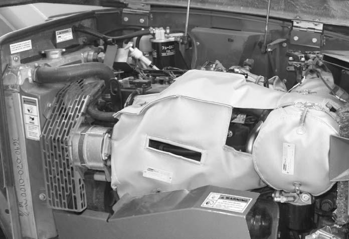
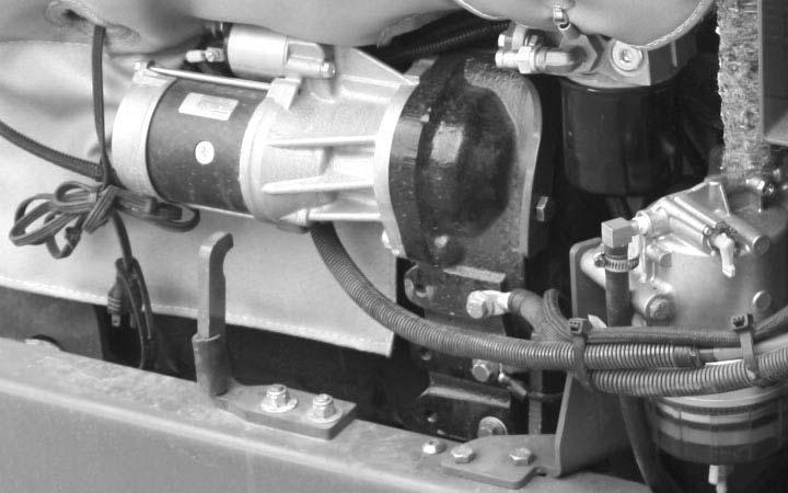
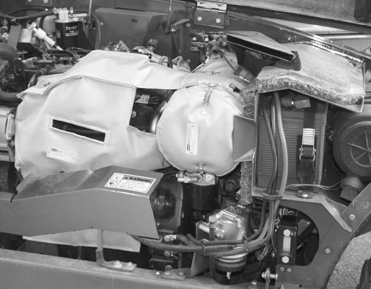
CHECKING EXHAUST SYSTEM
Examine the muffler and tail pipe for possible holes. Re-tighten any loose clamps and make sure the manifold outlet gasket is not leaking. Examine the exhaust insulating blanket for holes or tears. To prevent excessive heat build up in the engine compartment the insulating blanket should be replaced when it is damaged.
IMPORTANT: To prevent damaging the insulating blanket, do not spray it with high pressure water blast when cleaning the engine.
Service Every 2000 Hours or Two Years
Perform all other service requirements up to this point, as well as the following.
CHECKING HYDRAULIC SYSTEM RELIEF PRESSURES
Pressure settings for relief valves are pre-set at the factory. A test port is provided under the engine cover.
Before conducting any test port pressure checks, check the engine speed. Engine speed must be 1000 RPM at idle and 2530 RPM at high idle.
Steering Relief Pressure
Plug a 3000 psi (207 bar) oil- or liquid-filled gauge into the test port. Turn the steering wheel fully to the right or left. The gauge should read 2400 psi (165 bar).
Main Relief Pressure
Plug a 3500 psi (241 bar) oil- or liquid-filled gauge into the test port. Fully retract the boom forcing oil to flow over the relief valve. The gauge should read 3350 psi (231 bar).
Service As Required
EXHAUST FILTER SERVICE
The exhaust filter will provide several thousand hours of maintenance free operation. At some point the exhaust filter will require professional service to remove accumulated ash buildup. Adhering to the recommended engine oil and diesel fuel requirements will maximize the hours of operation before professional service is required. A diagnostic code will display in the multi-function display screen to indicate when professional exhaust filter service is required. This professional exhaust filter service must be performed by an authorized Manitou dealer.
STORING THE MACHINE
If the Telescopic Handler will not be operated for a period of three months or more, prepare and store it using the following procedure:
NOTE: If the storage area is outdoors or in a harsh environment, the storage procedure should be followed if the Telescopic Handler is to be stored for one month.
Before Storage
Perform the following prior to placing the machine in storage:
1Wash off the entire machine. 2.Lubricate all grease fittings as described in the
Lubrication chapter of this manual. 3.Change engine oil as outlined in the Service and
Storage chapter of this manual. 4.If the machine will not be operated for a month or longer, apply grease to all exposed hydraulic cylinder rod areas. 5.Disconnect the battery cable clamps and cover the battery or remove the battery from the machine and store it separately. 6.If the ambient temperature (at any time during the storage period) is expected to drop below freezing, make sure the engine coolant is either completely drained from the radiator and engine block or that the amount of anti-freeze in it is adequate to keep the coolant from freezing. Refer to the engine manual for anti-freeze recommendations and quantities.
During Storage
1.About once each month, connect the battery and check all fluid levels to make sure they are at the proper level before starting the engine. 2.Start the engine and allow it to run until it warms up and then move the machine a short distance to help relubricate the internal parts. Run the engine until the battery has a chance to recharge and then shut it off. IMPORTANT: If it is desired to operate the hydraulic cylinders at this time, BE SURE to wipe the protective grease (and any adhering dirt) from the cylinder rods prior to starting the engine. After operating, BE SURE to recoat the cylinder rods with grease if the machine is to be returned to storage.
After Storage
After removing the machine from storage and before operating it, perform the following:
1.Change engine oil and filter to remove condensation or other residues. 2.Wipe off grease from cylinder rods. 3.Lubricate ALL grease fittings. 4.Review and re-familiarize yourself with all safety precautions as outlined in the Safety chapter of this manual. 5.Follow the starting and warm-up procedures as outlined in the Operation and Adjustments chapter of this manual.