13 minute read
REASSEMBLY OF TRANSMISSION


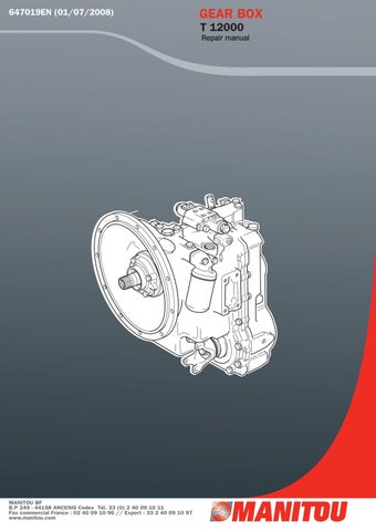
Figure 344
Install capscrew and washers. Tighten to specified torque. See torque chart.
REASSEMBLY OF TRANSMISSION (See Cleaning and Inspection Page)
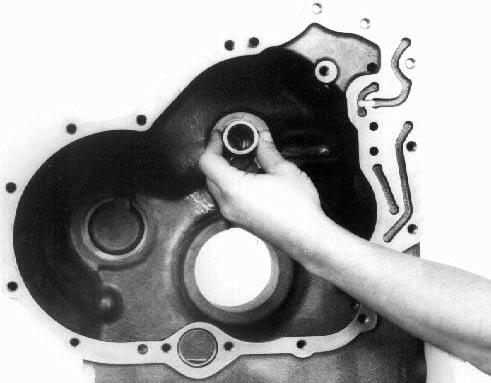
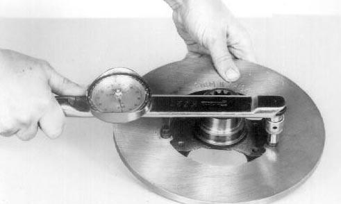
Figure 345
Install forward-reverse oil distributor sleeve in transmiision case with inside diameter chamfer out, (toward front of transmission), and the notch in the distributor aligned up with the retaining set screw hole in the transmission case.
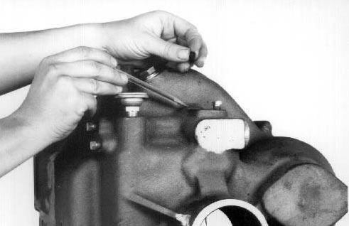
Figure 346
Apply Loctite #243 and install set screw in transmission case and in oil distributor sleeve. Install set screw plug.
Figure 347
Install reverse and forward clutch shaft rear bearing in transmission case.
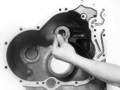
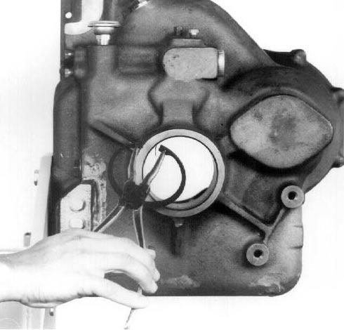
Figure 348
Install rear output bearing locating ring in transmission case.
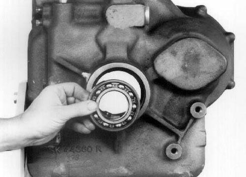
Figure 349
Install output bearing against locating ring.
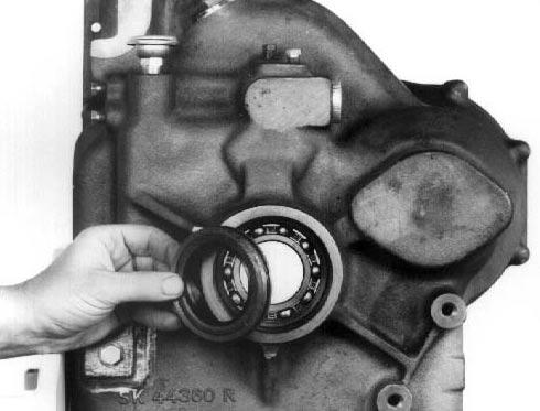
Figure 350
Position oil seal sleeve in transmission case with recessed portion of oil seal toward output bearing. This leaves a space between oil seal and output bearing.
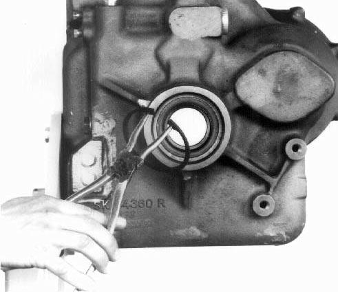
Figure 351
Install oil seal sleeve retainer ring.
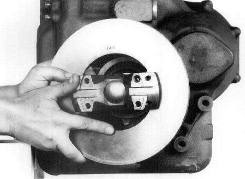
Figure 352
Install output flange through oil seal and rear output bearing. Use caution as not to damage seal.
Figure 353
Install output flange to rear bearing retainer ring.

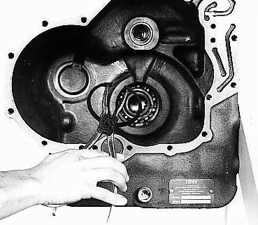
Figure 354
Install 3rd gear shaft bearing locating ring.
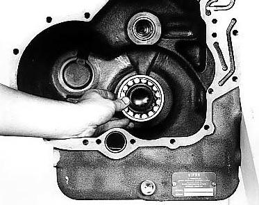
Figure 355
Install 3rd gear shaft bearing.
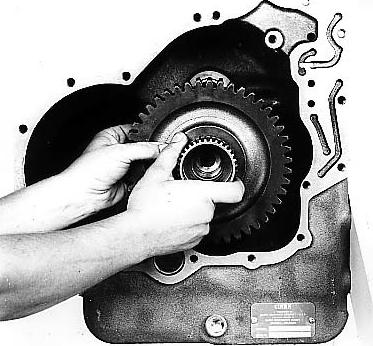
Figure 356
Position 3rd gear and shaft through bearing and into output flange.
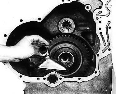
Figure 357
Position the oil suction tube and screen in transmission case.
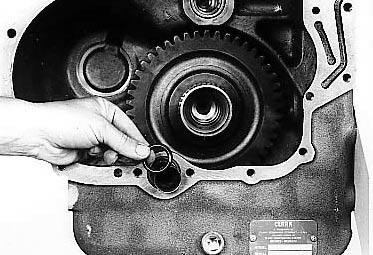
Figure 358
Push suction tube through opening in case and install "O" ring.
Figure 359
Position oil baffle in transmission case.
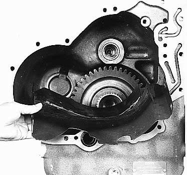
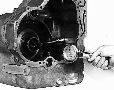
Figure 360
Install oil baffle capscrews and tighten to specified torque. See torque chart.
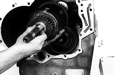
Figure 361
Position the forward and reverse clutch assembly shaft through the rear needle bearing and into the oil distributor sleeve. Use extreme caution as not to damage or break the clucth shaft oil sealing rings.
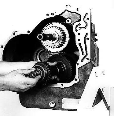
Figure 362
With the 3rd speed clutch shaft rear pilot bearing on shaft, install 3rd clutch assembly in 3rd clutch gear disc hub. Align splines on 3rd gear disc hub with internal teeth of friction discs. Do not force this operation. Gear splines must be in full position with internal teeth of all friction discs. Use caution as not to damage pilot bearing. NOTE : A 4 and 6 speed transmission will also have a 4th High clutch on with 3rd clutch.
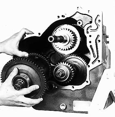
Figure 363
With the rear clutch shaft roller bearing in position on shaft, install the 1st and 2nd clutch assembly in transmission case.
Figure 364
Position new transmission case to converter housing gasket on transmission case. A light coat of grease will hold gasket in position.
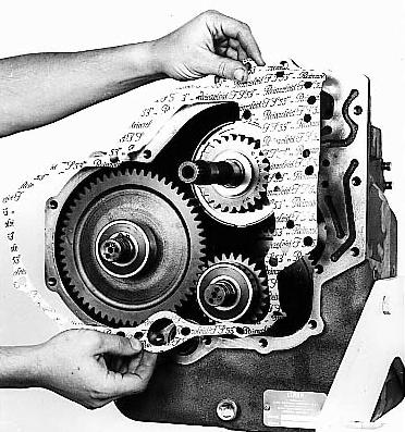
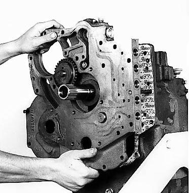
Figure 365
Install spacer plate assembly on transmission, aligning clutch shafts with opening in spacer plate. Use caution as not to damage oil sealing rings. Spacer plate must be tight against transmission case. Do not use bolts to pull spacer plate and case together. Tap spacer plate into position at dowel pins. Install spacer plate to transmission case capscrews.
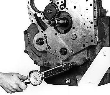
Figure 366
See "NOTE" on Figure I for proper capscrew installation and torque.
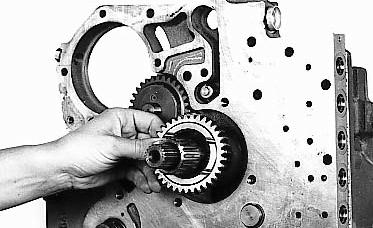
Figure 367
Position impeller hub gear on stator support.
Figure 368
Position spacer to converter housing gasket on spacer. A light coat of grease will hold gasket in place.
Figure 370
Tighten bolts to specified torque. See "NOTE" in Figure 369. See Figures I and J for proper screw location and installation.
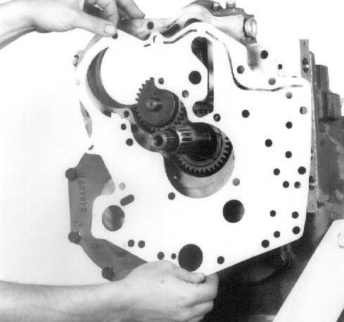
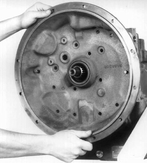
Figure 369
The use of aligning studs will facilitate converter housing to spacer installation. The transmission could be laid down to align the end of the clutch shafts into sealing ring sleeves in converter housing . Do not force this operation. Converter housing must be tight against transmission spacer.
NOTE : Do not use bolts to pull converter housing in place.Install converter housing to transmission case screws and lockwashers. See Figures I and J for proper screw location and installation.
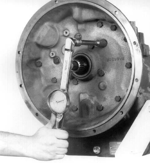
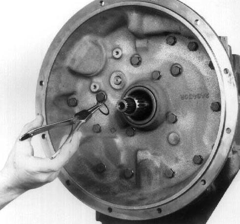
Figure 371
Install converter locating ring on turbine shaft.
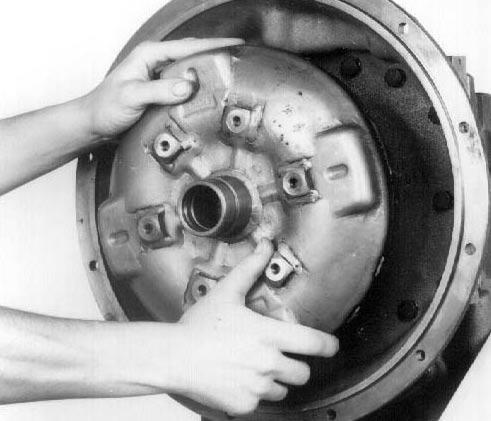
Figure 372
Position converter assembly on stator support and turbine shaft.
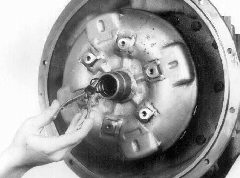
Figure 373
Install converter assembly retainer ring.
Figure 374
With new "O" ring in place, install bore plug in converter assembly.
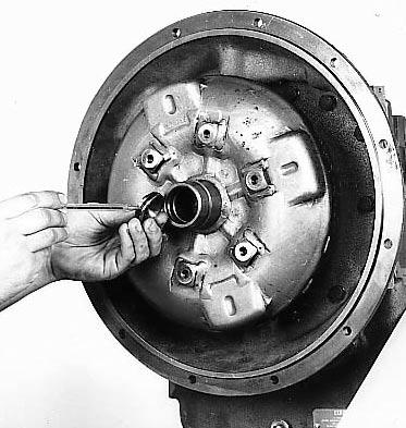
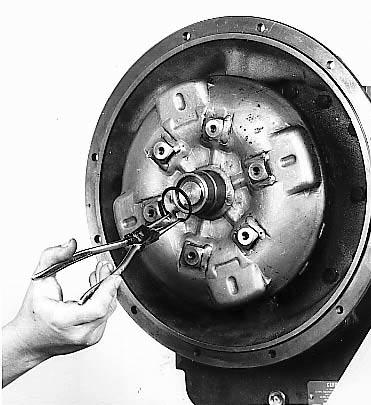
Figure 375
Install bore plug retainer ring.
A 4 and 6 speed transmission will have two (2) different length solenoid cartridges. Three (3) cartridges will be used for speed selection in lower three holes and two (2) cartridges will be used in upper two holes for direction selection (Forward-Reverse). The three (3) cartridges will be of same length but longer than the two (2) direction cartridges.
A 3 speed transmission will have two (2) different length solenoid cartridges. Two (2) cartridges will be used for speed selection in lower two holes and two (2) cartridges will be used in upper two holes for direction selection (Forward-Reverse). The two (2) speed cartridges will be of same length but longer than the two (2) direction cartridges. A bore plug is used in the center hole on 3 speed only.
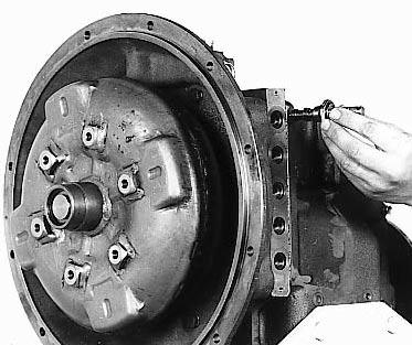
Figure 376
With new "O" rings in position on the solenoid cartridges, install cartridges as explained above. The 3.100 [78,74 mm] length cartridges go in the top two holes, the 4.100 [104,14 mm] length cartridges go in the two (2) or three (3) bottom holes depending on speed of transmission.
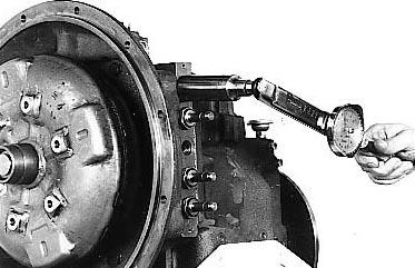
Figure 377
Tighten cartridges to specified torque. See assembly instruction drawing.
Figure 378
Position a new cartridge to coil "O" ring on cartridge.
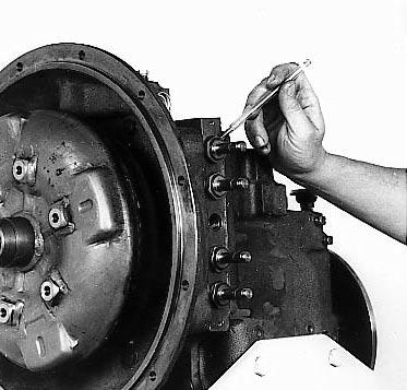
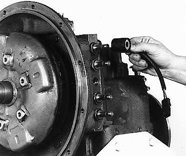
Figure 379
Install coil and wire lead assembly on cartridge.
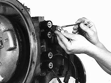
Figure 380
With new "O" ring in position, install coil to cartridge nut.
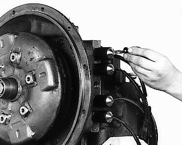
Figure 381
Tighten cartridge nut per assembly instruction drawing.
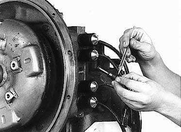
Figure 382
On 3 speed transmission only, position new "O" rings on the center hole bore plug. Install plug and tighten to specified torque.
DUAL MODULATION INSTALLATION
FOR SINGLE MODULATION AND MECHANICAL INCHING SEE PAGE 70.
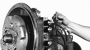
Figure 383
Install modulation diverter in trans mision case.
Figure 384
With new lower end "O" ring on modulation valve sleeve, install sleeve and spring assembly in transmission case.
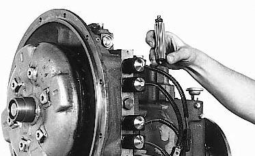

Figure 385
With new "O" ring in position, install modulator valve housing over spring and sleeve assembly.
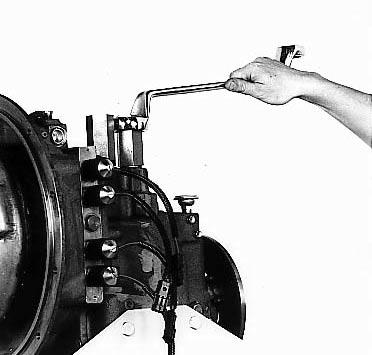
Figure 386 Tighten modulator valve housing 60-65 lbf·ft [81-88 N·m].
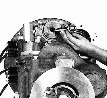
Figure 387 Install regulator valve assembly in converter housing.
1/2" drive socket 1/8" fillet weld
Figure 388A
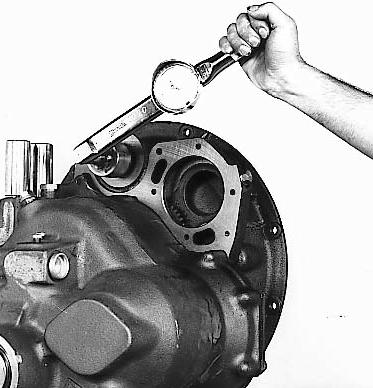
Figure 388
A special tool can be fabricated to tighten the regulator valve (See Figure 388A). Tighten valve assembly sleeve 45-50 lbf·ft [61,1-67,7 N·m].
Figure 389
Install oil filter assembly on regulating valve. Tighten filter 20-25 lbf·ft [27-34 N·m].
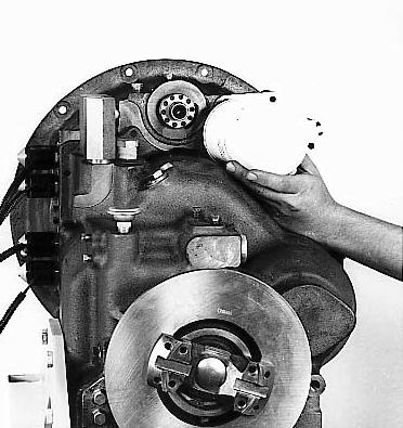
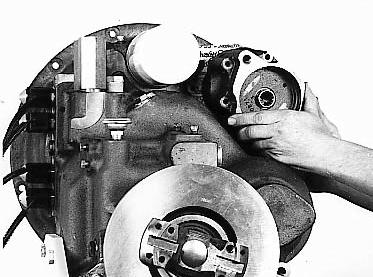
Figure 390
With new gasket in place, install charging pump in converter housing.
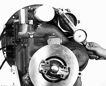
Figure 391
Install charging pump to converter housing bolts and washer and tighten to specified torque. See torque chart.
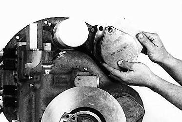
Figure 392
If auxiliary pump is used, it is not necessary to install the permanent pump hole cover. With new gasket in place, install pump hole cover on charging pump. Install bolts and washers and tighten to specified torque. See torque chart.
Figure 393
Install caliper brake mounting screw through brake assembly and through locknut. Apply Loctite #262 to threads and install screw in transmission case.
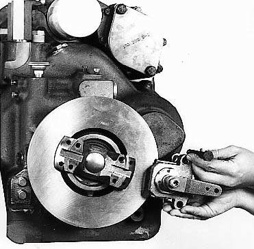
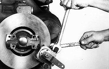
Figure 394
Mounting screws to be installed to allow free movement of caliper pads to disc. Tighten jam nut. See torque chart. See page 87 for brake information.
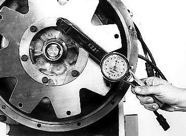
Figure 395
See special section on page 80 for drive plate installation.
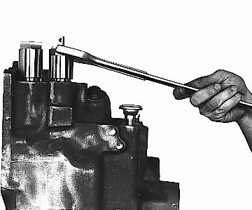
Figure 396
Remove inching valve housing.
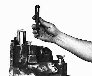
Figure 397
Remove inching return spring, actuator rod, and regulator spring.
Figure 400
Remove modulator valve housing and "O" ring.
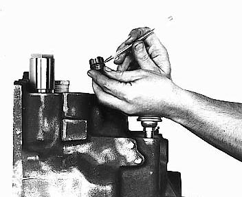
Figure 398
Remove inching sleeve and "O" ring.
Figure 399
Remove inching spool.
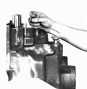
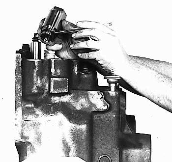
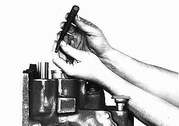
Figure 401
Remove modulator valve outer, middle, and inner springs and spring stop.
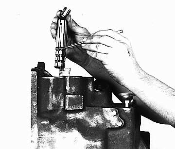
Figure 402
Remove modulation housing sleeve and accumulator spool.
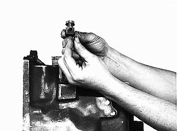
Figure 403
Remove shuttle sleeve and spool.
DISASSEMBLY AND REASSEMBLY OF MODULATOR VALVE ASSEMBLY
DISASSEMBLY
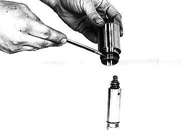
Figure 404
Remove modulator valve body "O" ring.
Figure 405
Remove modulator valve outer, middle, and inner springs and spring stop. Reference Figure 401.
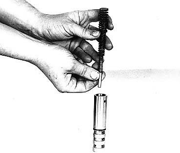
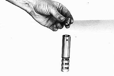
Figure 406 Remove accumulator spool. Reference Figure 402.
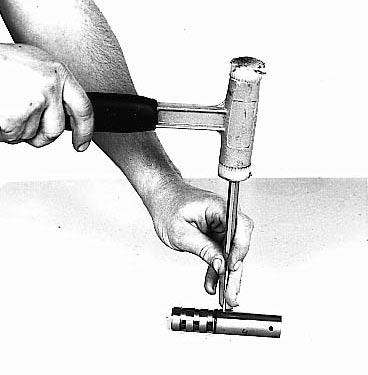
Figure 407
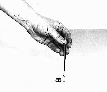
Remove modulator sleeve pin.
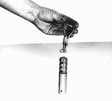
Figure 408
Remove regulator spool assembly retainer ring.
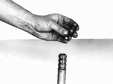
Figure 409
Remove regulator spool stop, spring, and spool and sleeve assembly.
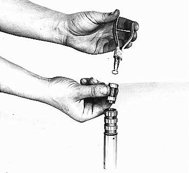
Figure 410
Remove regulator spool sleeve retainer ring.
Figure 411
Remove regulator spool sleeve assembly. Remove "O" ring.
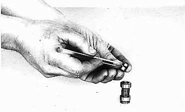
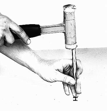
Figure 412
Remove sleeve check ball retainer pin.
Remove check ball.
Figure 413
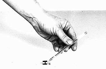
Figure 414
Install a new "O" ring on regulator spool sleeve. Position check ball in sleeve.
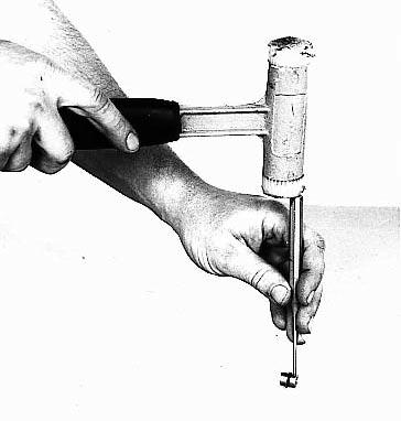
Figure 415
Install check ball retai,er pin.
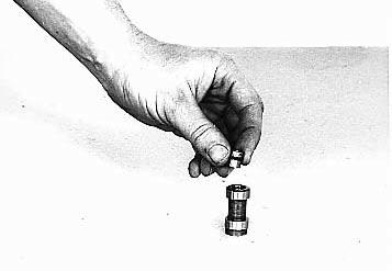
Figure 416
Position sleeve and ball assembly in regulator spool with check ball retainer pin up.
Figure 419
Install regulator spool stop, spring, and regulator spool and sleeve assembly in housing sleeve.
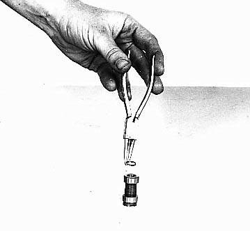
Figure 417
Install sleeve retainer ring.
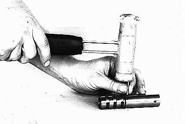
Figure 418
Install housing sleeve pin.
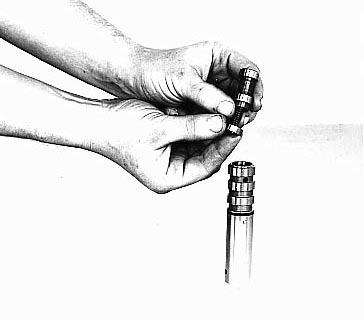
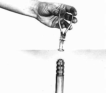
Figure 420
Compress regulator spool spring and install retainer ring.
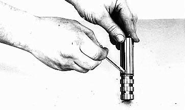
Figure 421
Position new "O" ring on modulation sleeve.
SINGLE MODULATION AND MECHANICAL INCHING INSTALLATION
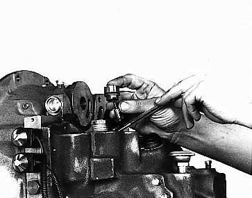
Figure 422
Install a new "O" ring on inching sleeve. Install inching spool in sleeve. Install spool and sleeve in inching control bore.
Figure 423
Install inching regulator spool spring.

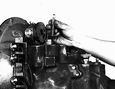
Figure 424
Install inching actuator rod over spring.
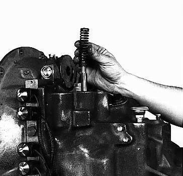
Figure 425
Install inching return spring.
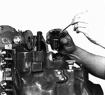
Figure 426
With new actuator rod oil seal in position and new "O" ring on inching housing, install housing over actuator rod and thread into inching bore.
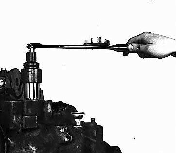
Figure 427
Tighten inching valve housing to specified torque. See assembly instruction drawing.
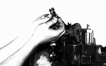
Figure 428
Position shuttle spool in shuttle sleeve.Install spool and sleeve in modulator valve bore.
Figure 429
With new "O" ring in position, install modulation housing sleeve assembly in bore.
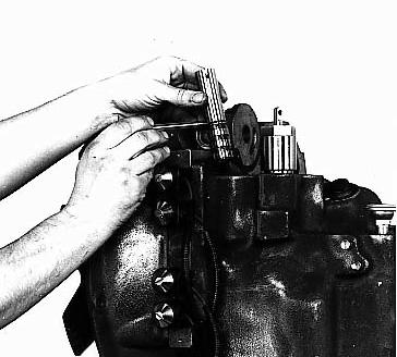
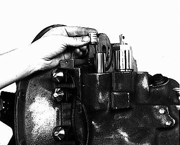
Figure 430
Install accumulator spool in housing sleeve as shown.
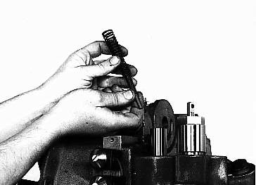
Figure 431
Install stop pin, inner, middle, and outer springs in accumulator and housing sleeve.
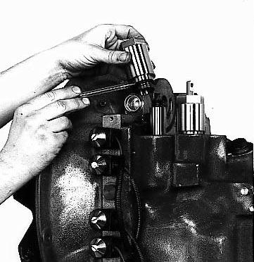
Figure 432
Position a new "O" ring on modulator valve housing. Thread housing into valve bore.
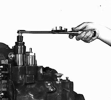
Figure 433
Tighten modulator valve housing to specified torque. See assembly instruction drawing.