1 minute read
TORQUE SPECIFICATION


Use the following torques unless otherwise specified.
NOTE: The bolts and nuts used are "Metric" sizes, be sure to use metric tools. Be careful to use bolts and nuts of correct size s and thread pitches when assembling this tractor.
NOTE : Nominal size is shown in the "size" column.
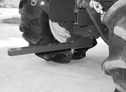
Preparation Replacement Of Drawbar
1.Place the tractor on level and hard ground. Put the range shift lever in LOW position. Apply the park brakes and stop the engine. Put blocks in front of and behind of the front wheels.
(Max 28 XL Only)
1.Remove the drawbar, when it is attached to the storing position.
2.Install the Drawbar with Pin and Snap pin to the bracket.
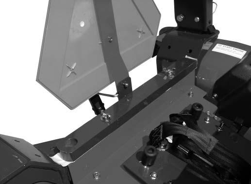
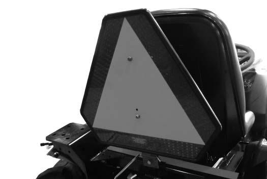
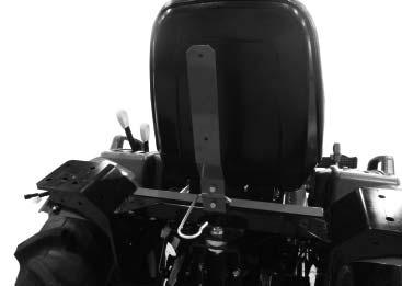
DISASSEMBLING SMV (Slow Moving Vehicle)
EMBLEM and UPPER LINK HOOK
1. Remove the S MV Emblem by removing the 2 - M6 x 16 mm screw bolts from the S MV Emblem Bracket.
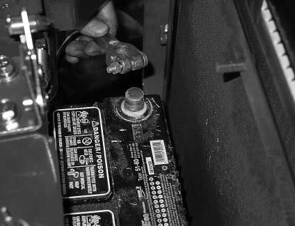
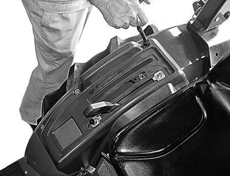
DISASSEMBLING SEAT, COVER AND FENDER
1.Disconnect the connectors. Remove the seat by removing the snap pin.
2.Remove the S MV Emblem Bracket and Upper Link Hook by removing the 2 - M8 x 20 mm Bolts from the Frame.
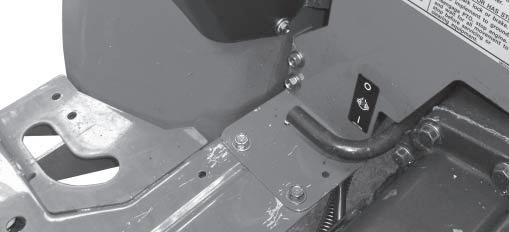
2.Remove the grip of position control lever, and the R.H.lever guide by removing the 5-bolts (M6x16mm).
3.[max22/25]
Re move t he R.H. f ende r by remov ing t he 2- bol ts (M8x25mm) and the 2-bolts (M8x16mm).
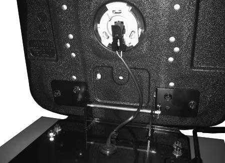
4.Disconnect the connector from the main harness. Remove the band.
BOLTS (M8x25mm)
BOLTS (M8x16mm)
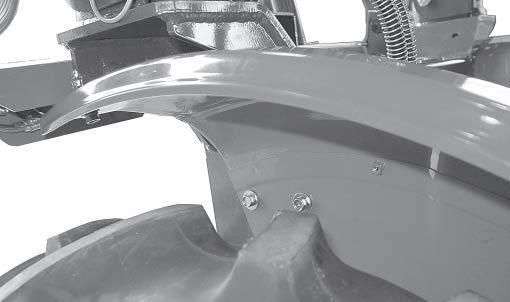
3.[max28XL]
Re move t he R.H. f ende r by remov ing t he 2- bol ts (M8x20mm), 2-bolts (M8x25mm) and 3-bolt s (M8x16mm).
BOLTS (M8X20mm)
BOLTS (M8X16mm)
FENDER
BOLTS (M8X25mm)
R.H. FENDER BOLTS
5.Remove t he sea t brac ket by remo v ing t he 4-nu ts from center cover (M6).
FENDER
BOLTS (M8X16mm)
6.Remove the 2-bolts (M6x16mm).