13 minute read
INSTALLING MOUNT AND HYDRAULIC COMPONENTS


CAUTION: Before leaving tractor seat, stop engine, lock brake, relieve hydraulic pressure and remove key.
CAUTION: Do Not allow bystanders in work area.
Installation Notes
• Remove all mounting brackets from crate.
• Clean threaded holes in the tractor frame with a tap of the proper size. Paint, rust and/or debris in threads may cause bolts to mis-align or not tighten correctly.
• This mounting kit may have both metric and standard NF (fine thread) or NC (course thread) fasteners. Insure that the proper fasteners are used in the correct locations.
• Leave all mounting hardware loose until mounting kit is completely installed.
• After the mounting kit installation is complete, tighten all hardware to the specifications given in the bolt torque chart or per specifications given in instructions.
• After the first hour and then after every 4 hours for the first day of operation, all mounting hardware should be checked for proper torque specifications.
Tractor Preparation
Tractor will require setup, please consult your Backhoe Operator’s Manual for proper ballasting and other important safety precautions.
Installation of the Backhoe on to the tractor will require that a loader has already been installed.
NOTICE: If equipped, remove loader rear ballast.
NOTICE: Remove tractor 3-point center link, lift links and lower draft arms before proceeding and hydraulically raise 3-point. Refer to your Tractor Operator’s Manual for proper removal procedure.
NOTICE: Removal or reposition of tractor draw bar may be necessary.
NOTICE: Some loader mounting components attached to tractor may be removed and discarded.
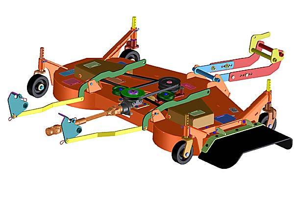
NOTICE: Remove belly mower (if so equipped) from tractor to allow backhoe to be installed. See figures 1 and 1A for components to be removed and figures 2 and 2A for components that remain on the tractor. Figures 1 and 2 refer to mowers with serial numbers 2999 and lower. Figures 1A and 2A refer to mowers with serial numbers 3001 and higher. See your Mower Deck Manual for assembly and removal of mower components.
NOTICE - To ease installation of backhoe mounting components to tractor, the removal of the rear tires is recommended.
1. Turn off the ignition, engage the parking brake and block the front tires.
2. Using a jack or chain hoist, carefully raise the rear of the tractor until the rear tires are approximately 1” - 2” off the ground.
NOTICE: For overall unit stability during installation, do not raise rear end higher than required for wheel removal.
3. Support the rear of the tractor on jack stands positioned under the rear axles.
MOWER DECK PARTS THAT NEED TO BE REMOVED BEFORE INSTALLING BACKHOE AND MOUNTS ARE SHOWN. PARTS INCLUDE THE DECK ASSEMBLY, DRIVELINE AND LIFT LINKAGE ASSEMBLY. REFERENCE YOUR MOWER DECK MANUAL.
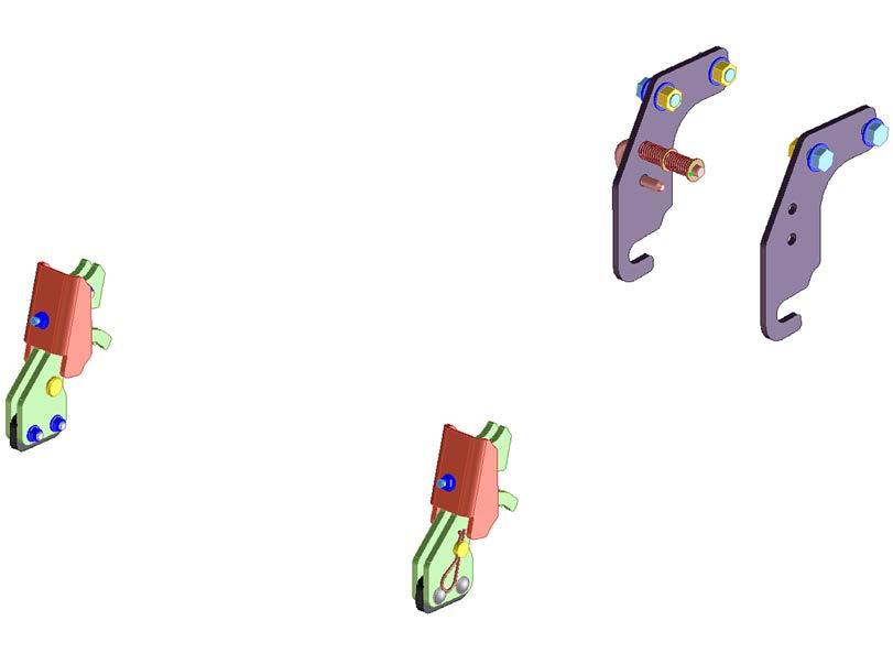
MOWER DECK PARTS THAT REMAIN ON TRACTOR WHEN BACKHOE IS INSTALLED ARE SHOWN. PARTS INCLUDE FRONT HOOK ASSEMBLY AND MID-MOUNT ASSEMBLY. REFERENCE YOUR MOWER DECK MANUAL.
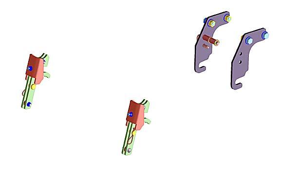
FOR MOWERS WITH SERIAL NUMBERS 3001 AND HIGHER.
MOWER DECK PARTS THAT NEED TO BE REMOVED BEFORE INSTALLING BACKHOE AND MOUNTS ARE SHOWN. PARTS INCLUDE THE DECK ASSEMBLY, DRIVELINE AND LIFT LINKAGE ASSEMBLY. REFERENCE YOUR MOWER DECK MANUAL.

FIGURE
FOR MOWERS WITH SERIAL NUMBERS 3001 AND HIGHER.
MID-MOUNT ASSEMBLY
Loader And Tractor Component Removal And Required Modifications
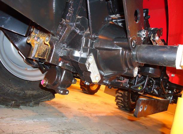
1. Remove and discard the four sets of hardware that attach the loader brace arms to the Loader Brace Arm Support Plate. Remove and discard four sets of hardware that attach the Brace Arm Support Plate and 3-point Pivot Support Weldment to the tractor Rear Axle Casting and tractor ROPS Support. Brace Arm Support Plate and 3-point Pivot Support Weldment can also be discarded. See figures 3 and 4.
2. Remove and discard 3-point Pivot Weldments but retain four hardware sets for later use. See figures 3 and 4.
3. Remove PTO shield and discard hardware. PTO shield will be assembled later in the mount assembly process. See figure 3.
4. Remove and discard the four sets of hardware on the bottom of the tractor that hold the tractor draw bar weldment to the tractor casting. See figure 5.
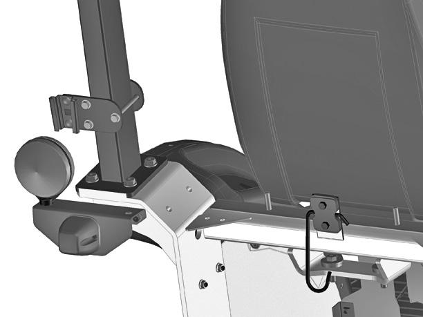
5. Remove the SMV stake and wire form hanger from the mount lug on the tractor. Retain the hardware and wire form hanger for later use. Remove the SMV sign LOADER from the stake. Discard hardware that was removed. Retain the SMV sign for later use. See Figures 6 and 7.
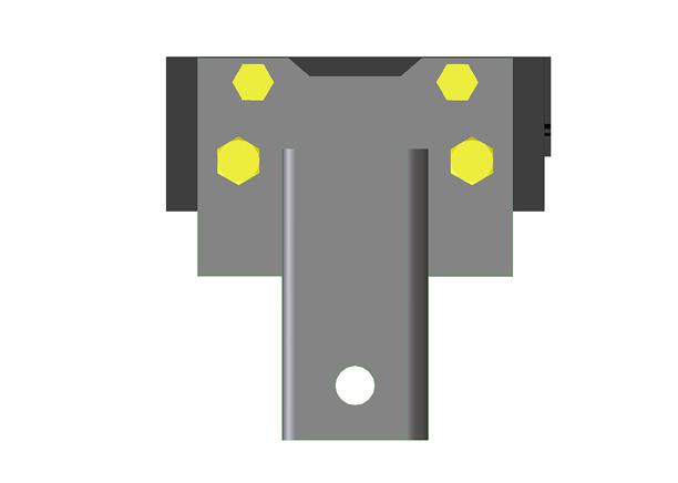
6. Attach Cover Weldment (51) to tractor SMV mount lug and wire form hanger using existing hardware removed earlier. See figure 6.
7. Attach the SMV Socket (25) to the Rear SMV Plate (56) using two 5/16-18 x 3/4 Carriage Bolts (1), two 5/16 Lock Washers (9) and two 5/16-18 Nuts (4). See figure 6.
8. Secure SMV Rear Plate (56) with SMV Socket attached, to the SMV Front Plate (55) on the LH side of tractor ROPS post using three 5/16 NF x 4” Bolts (52), six 5/16 Flat Washers (54) and three 5/16 NF Lock Nuts (53). Locate the bottom of the SMV Rear Plate and SMV Front Plate about 4-1/4” above the top of the ROPS mount plate. Tighten bolts. See figure 6.
9. Attach tractor SMV sign to SMV Stake (26) using two 1/4-20 x 3/4 Bolts (2), two 1/4 Lock Washers (8) and two 1/4-20 Nuts (3). See figure 8.
THIS IS WHERE 3-POINT PIVOT WELDMENT IS REMOVED FROM
TRACTOR REAR AXLE CASTING
TRACTOR ROPS SUPPORT
TRACTOR REAR AXLE
THIS IS WHERE THE 3-POINT PIVOT SUPPORT WELDMENT AND LOADER BRACE ARM SUPPORT PLATE IS REMOVED FROM
TRACTOR DRAW BAR LOWER BOLTS (4 SETS)
FRONT OF TRACTOR
TRACTOR DRAW BAR WELDMENT
REAR OF TRACTOR
LH SIDE TRACTOR ROPS POST
REAR SMV PLATE
SMV SOCKET
FRONT SMV PLATE
REAR OF TRACTOR
COVER WELDMENT
EXISTING TRACTOR HARDWARE
ROPS MOUNT PLATE

TRACTOR SMV MOUNT LUG
WIRE FORM HANGER
TRACTOR SMV STAKE THAT IS REMOVED
TRACTOR SMV SIGN
MAHINDRA BACKHOE KIT SUPPLIED SMV STAKE
Installing Right And Left Hand Lower Mount Weldments To Tractor
1. Remove and discard the two RH sets of hardware that attach the tractor draw bar weldment to the tractor, just below the rear tractor PTO shaft. See figure 9.
2. Attach the RH Lower Mount Weldment (45) to the tractor over the tractor draw bar weldment and install two M14 x 2.0 x 45 Bolts (37) and two 9/16 Hardened Washers (11) in the holes where the hardware was removed in step 1. Do not tighten hardware at this time. See figures 9 and 10.
3. Attach the RH Lower Mount Weldment (45) to the underside of the draw bar where the hardware was removed in step #4 of the “Loader Component Removal and Required Modifications” section of this manual. Use one M14 x 2.0 x 45mm Bolt (37) and one 9/16 Hardened Washer (11) in the rearward hole. Use one M12 x 1.75 x 45mm Bolt (36) and one 1/2 Hardened Washer (10) in the forward hole. Do not tighten hardware at this time. See figure 11.
4. Install the two RH sets of hardware that were removed in step 2 of the “Loader Component Removal and Required Modifications” section of this manual to secure the RH Lower Mount Weldment (45) to the tractor rear casting where the 3-point pivot weldments were removed from. Do not tighten hardware at this time. See figures 9 and 10.
5. Repeat steps 1 through 4 for attaching the LH Lower Mount Weldment (46) to the LH side of the tractor rear casting and draw bar weldment. Do not tighten hardware at this time. See figures 9, 10 and 11.
Installing Right And Left Hand Rear Mount Weldments To Tractor
1. Remove and discard the two bolts to the right side of the upper 3-point link arm bracket. Keep the two bolts to the left side in place at this time. See figure 9.
2. Install RH Rear Mount Weldment (47) to the rear of the tractor over the upper 3-point link arm bracket and secure using two M14 x 2.0 x 50mm Bolts (39) and two 9/16 Hardened Washers (11). Do not tighten hardware. See figures 9 and 10.
3. Remove and discard the two bolts to the left side of the upper 3-point link arm bracket. See figure 9.
4. Repeat step 2 for installing the LH Rear Mount Weldment (48) to the rear of the tractor over the upper 3-point link arm bracket. Do not tighten hardware at this time. See figures 9 and 10.
Install Right And Left Hand Side Mount Weldments To The Tractor
1. Attach the RH Side Mount Weldment (49) to the outer face of the tractor rear axle housing where the loader brace arm support plate and the 3-point pivot support weldment was removed in step 1 of the “Loader and tractor Component Removal and Required Modifications” section of this manual. Secure using three M14 x 2.0 x 40 Bolts (38) and three 9/16 Hardened Washers (11). See figures 9 and 10.
2. Repeat step 1 for the LH Side Mount Weldment (50). Do not tighten hardware at this time. See figures 9 and 10.
ATTACH RIGHT AND LEFT HAND LOWER MOUNT WELDMENTS TO RIGHT AND LEFT HAND REAR MOUNT WELDMENTS
1. Attach RH Lower Mount Weldment (45) to RH Rear Mount Weldment (47) using three M16 x 2.0 x 45 Bolts (40), six 5/8 Hardened Flat Washers (12) and three M16 Nuts (6). Be sure that bolt heads are directed from the inside of the tractor to the outside. Do not tighten hardware. See figures 9 and 10.
2. Repeat step 1 for attaching LH Lower Mount Weldment (46) to LH Rear Mount Weldment (48). Do not tighten hardware. See figures 9 and 10.
ATTACH RIGHT AND LEFT HAND LOWER MOUNT WELDMENTS TO RIGHT AND LEFT HAND SIDE MOUNT WELDMENTS
1. Attach RH Lower Mount Weldment (45) to RH Side Mount Weldment (49) using three M16 x 2.0 x 45mm Bolts (40), six 5/8 Hardened Washers (12) and three M16 x 2.0 Nuts (6). Do not tighten hardware at this time. See figures 9 and 10.
2. Repeat Step 1 for LH Lower Mount Weldment (46) to LH Side Mount Weldment (50). Do not tighten hardware at this time. See figures 9 and 10.
ATTACH RIGHT AND LEFT HAND SIDE MOUNT WELDMENTS TO THE RIGHT AND LEFT HAND LOADER BRACE ARMS
1. Attach RH Side Mount Weldment (49) to the RH Loader Brace Arm using two M14 x 2.0 x 40mm Bolts (38), four 9/16 Hardened Washers (11) and two M14 x 2.0 Nuts (5). Do not tighten hardware at this time. See figures 9 and 10.
2. Repeat step 1 for LH Side Mount Weldment (50) to the LH Loader Brace Arm. Do not tighten hardware at this time. See figures 9 and 10.
Install Pivot Pins Into Right And Left Hand Lower Mount Weldments And Side
MOUNT WELDMENTS
1. Insert Pivot Pin (44) through the Bushings in the RH Side Mount Weldment (49) and then into the RH Lower Mount Weldment (45). Secure with Lock Pin (24). See figure 9.
2. Repeat step 1 for Pivot Pin (44) through LH Side Mount Weldment (50) and into LH Lower Mount Weldment (46). See figure 9.
NOTICE: Be sure that when hardware for mount kit is tightened that the Pivot Pin (44) is free to move in and out.
Install Pto Shield To Tractor
1. Install PTO shield to tractor over the RH and LH Lower Mount Weldments (45 and 46) using two M12 x 1.75 x 45mm Bolts (36) and two 1/2” Hardened Washers (10). Do not tighten hardware. See figures 9 and 10.
NOTICE: Tighten and torque all hardware installed to this point. Torque order and specifications are shown in figures 10 and 11.
Reinstall rear tires if previously removed. Torque to proper specifications found in your tractor operator’s manual.
NOTICE: Tractor 3-point linkage is compatible with mounts installed up to this point. However, to install backhoe to tractor backhoe mounting and to operate backhoe these components need to be removed.
TRACTOR UPPER 3-POINT LINK ARM BRACKET
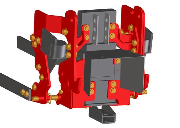
LH
RH
RH REAR MOUNT WELDMENT TRACTOR PTO SHIELD
RH LOWER MOUNT WELDMENT
RH SIDE MOUNT WELDMENT
TRACTOR DRAW BAR WELDMENT
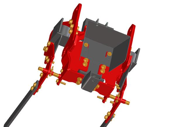
SIX SETS OF HARDWARE #7 225 FT LBS
SIX SETS OF HARDWARE #5 98 FT LBS
SIX SETS OF HARDWARE #8 225 FT LBS
FOUR SETS OF HARDWARE #6 98 FT LBS
FOUR SETS OF HARDWARE #9 98 FT LBS
FOUR SETS OF EXISTING TRACTOR HARDWARE #4 68 FT LBS
TWO SETS OF HARDWARE #2 68 FT LBS
TWO SETS OF HARDWARE #3 98 FT LBS
TWO SETS OF HARDWARE #3 68 FT LBS
FOUR SETS OF HARDWARE #1 98 FT LBS
FIGURE 10
ASSEMBLY INSTRUCTIONS - HYDRAULICS
Avoid High Pressure Fluids
ESCAPING fluid under pressure can have sufficient force to penetrate the skin and cause serious injury. Be sure to stop engine and relieve all pressure before disconnecting lines. Be sure all connections are tight and that lines, pipes, and hoses are not damaged before applying pressure to the system. Fluid escaping from a very small hole can be almost invisible. Use a piece of cardboard or wood, not your hands, to search for suspected leaks. SEE A DOCTOR at once if injured by escaping fluid. Serious infection or gangrene can develop if proper medical treatment is not administered immediately.
NOTICE - Follow instructions carefully when connecting backhoe to tractor hydraulic system.
INSTALLING BACKHOE HYDRAULIC HOSE LINES FOR TRACTOR
NOTICE - Improper hydraulic hook up can cause serious damage to backhoe control valve or other hydraulic components.
INLET LINE (PRESSURE)
NOTICE: Place a container under INLET port to catch trapped oil.
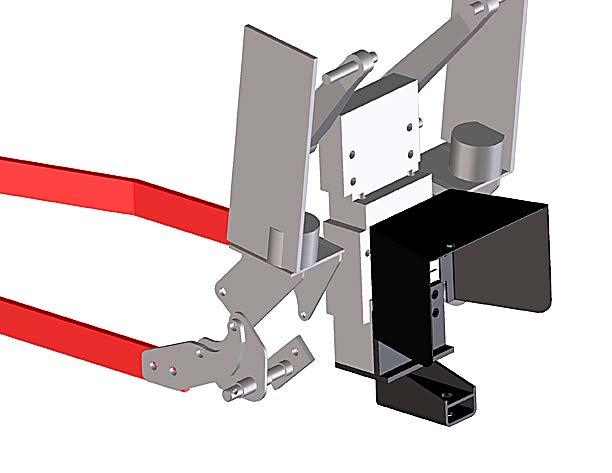
1. Remove valve cover from backhoe control tower.
2. Attach to left side of backhoe control valve (inlet), the 90 degree Adapter Fitting (16) and the 49” Hydraulic Hose (35). See figure 12.
3. Slide Hose Sleeve (30) over opposite end of Hose (35) and secure each end using Plastic Ties (28).
4. Install Coupler Nose (21) to opposite end of the hose (35).
CAUTION: Hose sleeves are installed to help protect the backhoe operator from escaping fluid under pressure. If it becomes damaged or lost, replace hose sleeve and plastic tie straps immediately.
OUTLET LINE (RETURN)
NOTICE: Plate a container under OUTLET port to catch trapped oil.
1. Attach to the far right end port (outlet) of the control valve, the Pipe Plug (7) and 90 degree Adapter Fitting (15). See figure 13.
2. Attach 48” Hose (31) to the fitting installed in step 1.
3. Install Dust Plug (22), Union Adapter (14), Check Valve (13), Straight Adapter (43) and Coupler Body (18) to the opposite end of hose (31).
Power Beyond Line
1. Attach to the Power Beyond Port on the RH side of the Control Valve 90 degree Adapter Fitting (16). See figure 13.
2. Install 49” Hydraulic Hose (35) to the 90 degree adapter union in the power beyond port on the front of the right hand side of the control valve. See figure 13.
3. Install Hose Sleeve (30) and “larger” Female Coupler (23) to the 49” Hose (35). Secure Hose Sleeve with Plastic Ties (28) at each end of hose assembly.
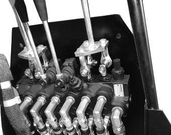
LOADER VALVE WITH COVER REMOVED
POWER BEYOND PORT
TANK PORT
TIE HOSES TOGETHER
LOADER VALVE
ROUTE HOSES FROM LOADER VALVE BEHIND LOADER MOUNT
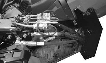
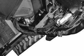
FIGURE 13
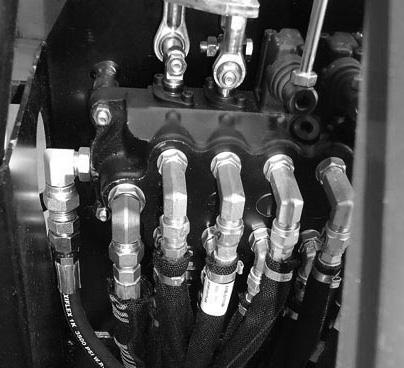
OUTLET PORT OF VALVE
POWER BEYOND PORT OF VALVE
Hydro Tractors
Installing Hydraulic Hose Lines To Tractor
NOTICE - Improper hydraulic hook-up can cause serious damage to tractor hydraulic components.
NOTICE: For ease of tractor and loader hydraulic plumbing, the loader may be removed from the tractor.
TRACTOR TANK PORT (RETURN)
1. Remove the hose end that is connected to the tank port on the loader valve. Opposite hose end stays connected to the tank port on the tractor hydraulic block. See figure 14.
2. Remove and discard hose that connects from the hydraulic block power beyond port to the loader valve power beyond port. See figure 14.
3. Install Tee Adapter Fitting (17) and 90 degree Adapter Fitting (42) to straight fitting in the tank port of loader valve. See figure 14.
4. Attach end of hose removed in step 1 to Tee Adapter Fitting (17). See figure 14.
5. Attach 95” Hose (34) to 90 degree Adapter Fitting (42) and run hose rerward over the RH axle and secure using Plastic Ties (27) as required. On the opposite end of the hose attah Dust Cap (20) and Coupler Nose (19). See figures 14, 15 and 18.
Backhoe Pressure Line From Loader Valve Power Beyond Port
1. Insert 100” Hose (33) into loader valve power beyond port 90 degree Adapter Fitting and rout hose rearward over the RH axle as shown. Slide Hose Sleeve (29) over opposite end of hose and secure using Plastic Tie (28). Attach Plastic Tag (41), 90 degree Adapter Union (15) and Coupler Body (23) to end of hose. Secure hose along its route with Plastic Ties (27) as required. See figures 14, 15 and 18.
POWER BEYOND LINE (To Tractor Manifold Block)
1. Install two 90 degree Adapter Fittings (42) to the straight adapter fitting of the power beyond port in the hydraulic block of the tractor. See figure 17.
2. Attach 83” Hose (32) to the 90 degree Adapter Union (42). Route the hose to the LH side of the tractor and rearward over the LH axle. Slide Hose Sleeve (29) over the opposite end of the hose and secure with Plastic Tie (28). Attach Coupler Nose (21) to hose end. Secure along its route with Plastic Ties (27) as required. See figures 16 and 17.
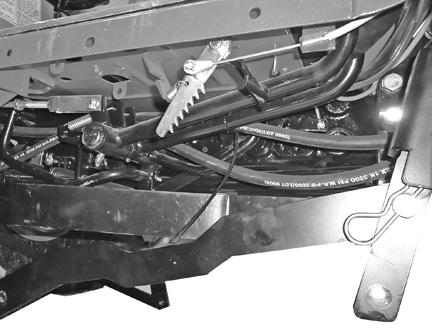
POWER BEYOND HOSE ROUTED ON THE LH SIDE OF THE TRACTOR AND SECURED.
ROUTING OF POWER BEYOND HOSE IN FRONT OF THE LOADER CROSS BRACE AND REARWARD ON THE LH SIDE OF TRACTOR.
PLASTIC TIE TO LOWER MOUNT WELDMENT
PLASTIC TIE TO U-PLATE ON TRACTOR
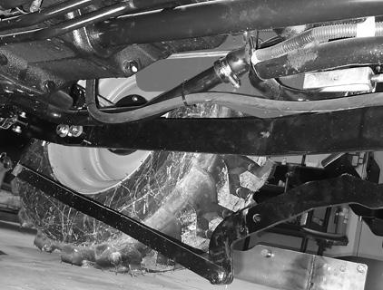
ROUTING OF PRESSURE AND TANK HOSES REARWARD ON THE RH SIDE OF TRACTOR. IF THERE IS CONCERN OF HOSES INTERFERING WITH LINKAGES YOU CAN ROUTE HOSES ALONG LOADER RAIL. JUST BE CAREFUL THAT THEY ARE TO THE TOP SIDE OF THE RAIL.
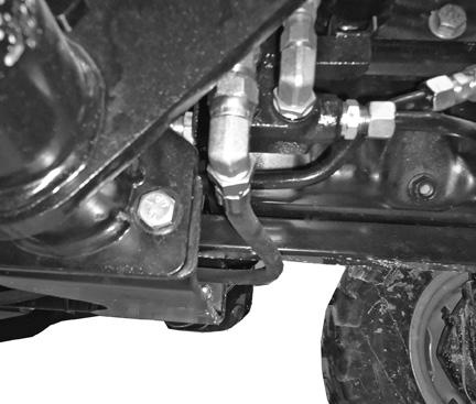
POWER BEYOND HOSE SHOULD BE TIED IN PLACE WITH DISTANCE FROM UPPER LINK BRACKET PLATE TO END OF COUPLER MEASURING ABOUT 9”
PRESSURE AND POWER BEYOND LINES CONNECTED WITH BACKHOE DISCONNECTED. DUST CAP ON TANK HOSE.
UPPER LINK BRACKET PLATE
PRESSURE AND TANK HOSES SHOULD BE TIED IN PLACE WITH DISTANCE FROM UPPER LINK BRACKET PLATE TO END OF COUPLER MEASURING ABOUT 5”
4-POINT MOUNT AND HYDRAULICS PARTS BREAKDOWN
4-POINT MOUNT AND HYDRAULICS PARTS BREAKDOWN
4-POINT MOUNT AND HYDRAULICS PARTS BREAKDOWN
TABLE 2—TORQUE-TENSION RELATIONSHIPS FOR SAE G RADES 2, 5, AND 8
Caution—The previously listed torque and resulting tension are provided as an advisory guide. Individual application discretion is recommended. The content has been presented as accurately as possible, but responsibility for its application lies with the user. Note 1—The stress area of threaded series not included in Table 2 may be computed from the equation:
Lubricating the bolts is the recommended method.
Lubed means cleaned dry bolts lubricated with standard medium viscosity machine oil.
Lubricate all contact areas of the bolts and washers.
TABLE 2—TORQUE-TENSION RELATIONSHIP FOR METRIC PROPERTY CLASSES
Caution—The previously listed torque and resulting tension are provided as an advisory guide. Individual application discretion is recommended. The content has been presented as accurately as possible, but responsibility for its application lies with the user. Note 1—The stress area of threaded series not included in Table 2 may be computed from the equation:
As = 0.7854 (D - 0.9382 P) 2
Lubricating the bolts is the recommended method.
Lubed means cleaned dry bolts lubricated with standard medium viscosity machine oil.
Lubricate all contact areas of the bolts and washers.