8 minute read
TROUBLESHOOTING THE MOWER


Problem
Mower will not raise.
Cause
• Lift linkage not properly attached or damaged.
• Dirt in hydraulic lines.
Correction
Attach or repair.
Change hydraulic system filter.
Mower cut is uneven.
• Mower not leveled properly.
• Tractor tires not inflated equally or properly.
• Cutting with attachment lift in raised position.
See Mower Adjustment.
See Tractor Manual Maintenance Section.
Lower attachment lift.
Mower cut is rough looking.
• Engine speed too slow.
• Ground speed too fast.
• Blades are dull.
• Mower drive belt slipping because it is oily or worn.
• Blades not properly fastened to arbors.
Set to full throttle. Slow down. Sharpen or replace blades. See Mower Blade Service Section. Clean or replace belt as necessary.
Engine stalls easily with mower engaged.
• Engine speed too slow.
• Ground speed too fast.
• Mower choked with grass.
• Cutting height set too low.
• Discharge chute jamming with cut grass.
• Engine not up to operating temperature.
• Starting mower in tall grass.
See Mower Blade Service Section. Set to full throttle. Slow down. Clean out mower deck. Cut tall grass at maximum cutting height during first pass. Cut grass with discharge pointing toward previously cut area. Run engine for several minutes to warm-up. Start the mower in a cleared area.
Excessive mower vibration.
• Blade mounting bolts are loose.
• Mower blades, arbors, or pulleys are bent.
• Mower blades are out of balance.
• Mower choked with grass.
Tighten 204 ft. lbs.
Check and replace as necessary. Remove, sharpen, and balance blades. See Mower Blade Service Section. Clean out mower deck.
Excessive belt wear or breakage. Mower drive belt slips or fails to drive.
• Bent or rough pulleys.
• Using incorrect belt.
• Excessive debris under cover.
Repair or replace. Replace with correct belt. Remove covers and clean out mower deck.
• Idler pulley spring broken or not properly attached.
• Excessive debris under covers.
• Mower drive belt broken.
Repair or replace as needed. Clean out mower deck. Replace drive belt.
Mower Deck Service Parts Breakdown
SPECIFICATIONS - 60” MOWER DECK
Shipping Weight of Base 60” Deck and Mounting
Specifications may vary depending on tractor model and are subject to change without notification.
Tractors must be equipped with a Rollover Protective System (ROPS) and seat belt that will provide better safety.
MAHINDRA 60” MOWER MOUNT KIT INSTRUCTIONS FOR MAX 22, 24 AND 25 TRACTORS
General Description
Tractor will require setup, please consult your tractor Operator’s Manual for important safety precautions.
NOTICE: Tractor will require the installation of midPTO Kit if one has not already been installed from the factory, before installation of mower deck.
Tractors Without Loaders
NOTICE: For those tractors NOT equipped with a loader, additional components are required to complete this kit installation. Please see that section within this installation manual.
Tractors With Loader
NOTICE: Remove Loader from tractor prior to installation of this kit. Refer to your Loader Operator’s Manual for proper removal procedure. Some loader mounting components attached to tractor will be removed and discarded.
NOTICE: Tighten all hardware to the torque requirements specified in the installation instructions or torque chart.
The terms RIGHT, LEFT, FORWARD and REAR are determined when in the correct operating position on the tractor seat.
NOTICE: For ease of assembly do not tighten any hardware until specified in the following instructions.
Pto Drive Shaft Installation
1. Install the PTO Drive Shaft (26) onto the mower deck gearbox input shaft. See Mount Kit parts breakdown, page 42.
2. Secure PTO Drive Shaft (26) to the gearbox input shaft using a Retaining Ring (20), and Internal Socket Head 5/16 NC x 1-3/4” Bolt (2) with Locknut (7). The Lock Nut must NOT be torqued. The Lock Nut should only be tightened until “snug” against the PTO Drive Shaft Yoke. Do not over tighten.
NOTICE: The Retaining Ring MUST be installed onto the gear box input shaft. Failure to install Retaining Ring will allow the PTO Drive Shaft to come off in the event the Shear Bolt breaks. Severe damage to mower and tractor components will result.
NOTICE: Should the two halves of the PTO Drive Shaft separate, please note the following reassembly process.
There is a blind spline between the drive shaft halves. The blind portion on the female spline on the tractor half, is located 180 degrees (opposite side) from the grease fitting. This portion should be matched up with the male spline on the mower half of the drive shaft.
Use a SAE multipurpose grease to lubricate all three fittings.
Front Mount Hanger Plate Installation
1. Install Front Mount Hangers (33) as shown on the inside of the tractor frame. Secure Hanger Plates using four 1/2-20 x 1-3/4 Bolts (4), four 1/2 Hardened Washers (13), four 1/2 Flange Head Lock Nuts (9), two 5/8-18 x 1-3/4 Bolts (6), four 5/8 Hardened Washers (15) and two 5/8 Nuts (11). Torque Hardware.
NOTE: Left Hand Front Mount Hanger has the preassembled spring loaded J-latch.
MID-MOUNT WELDMENT INSTALLATION
1. Assemble Rubber Bumper (24) to RH Mount Weldment (39) using one 5/16-18 x 1-1/4 Bolt (3), 5/16 Lock Nut (7) and two 5/16 Washers (12). Snug hardware.
2. Assemble Rubber Bumper (24) to LH Mount Weldment (41) using one 5/16-18 x 1-1/4 Bolt (3), 5/16 Lock Nut (7) and two 5/16 Washers (12). Snug hardware.
NOTE: Spacers (32) are only installed on tractors without loader. If tractor has loader installed, install Mount Weldments (39, 41) on the outside of the loader mounts.
3. Assemble RH Mount Weldment (39) to right hand side of tractor with (optional) Spacer (32) located between mount and tractor. Attach using two M12 x 1.75 x 45mm Bolts (27) and 1/2 Hardened Washers (13). Torque hardware.
4. Assembly LH Mount Weldment (41) to left hand side of tractor with (optional) Spacer (32) located between mount and tractor. Attach using two M12 x 1.75 x 45mm Bolts (27) and 1/2 Hardened Washers (13). Torque hardware.
Lower Mount Link Assembly
1. Preassemble Lower Link Weldment (40) and Front Link Weldment (38) using four M14 x 2.00 x 40mm Bolts (28), eight 9/16 SAE Hardened Washers (14) and Lock Nuts (10) as shown. Final adjustments will be made when the Mower Deck is installed onto the tractor. Snug hardware. Do not tighten at this time.
NOTE: Insert front bolts into center set of holes of the two halves. This is a starting point for front to rear pitch of the mower deck.
Rear Lift Rod Assembly
1. Assemble Lift Rod with Clevis Assembly (30) to Shackle Plate (34) using 1/2-20 Flange Head Lock Nut (9) and Lift Spring (19).
2. Tighten Flange Head Lock Nut to expose 1-3/8” (right hand) and 1-1/8” (left hand) of thread on Lift Rod.
NOTE: Further adjustment of Lock Nut will take place later when Mower Deck is installed.
3. Assemble Shackle Plates (34) to Right and Left Hand Lift Link Weldments (44, 45) using 1/2 NC-13 x 5 Bolts (5), four 1/2 SAE Hardened Washers (13) and Lock Nuts (8).
NOTE: Do not torque hardware. Snug only, as Shackle Plates must pivot on Link Weldments.
Lift Link Weldment Installation
1. Connect Right and Left Hand Lift Link Weldments (44, 45) to Left and Right Hand Mid Mount Weldments (39, 41) using 3/4 Clevis Pins (21) and Lynch Pins (23).
REAR HEIGHT OF CUT COMPONENT INSTALLATION
NOTE: For ease of access, rear tires may be removed if desired.
CAUTION: Avoid Injury. Remove wheels safely.
1. Use a safe lifting device and support tractor securely on jack stands. Block front wheels on both sides to prevent tractor movement.
2. Remove rear tires. Use caution as wheels can be heavy or difficult to handle when removing.
3. Lower tractor 3-Point Hitch Arms to lowest position.
4. Remove Sway Link Anchor Bracket and Sway Link assembly from tractor lower 3-Point Hitch Arm Pivot Shaft. Save hardware and bracket for reinstallation in a later step.
5. Slide Left Hand Lift Weldment (43) onto Lower 3-Point Hitch Arm Pivot Shaft and on top of hitch arm. Reinstall Sway Link Anchor Bracket and Sway Link Assembly using tractor hardware and torque to recommended value. Contact dealer for value.
6. Repeat step 4 and 5 for Right Hand Lift Weldment (42).
7. Grease both pivot joints.
LEFT SIDE INSTALLED VIEW
7. Assemble Left Hand Hitch Plate (37) to Left Hand Lift Weldment (43) using two 1/2 NC x 1-1/2 Carriage Bolts (1), two 1/2 Lock Nuts (8) and two 1/2 Hardened Washers (13). Torque hardware.
8. Repeat step 7 for Right Hand Hitch Plate (36).
GREASE ZERK
9. Assemble Lift Stiffener (35) to Left Hand Hitch Plate (37) and Right Hand Hitch (36) using four 1/2 NC x 1-1/2 Carriage Bolts (1), four 1/2 Lock Nuts (8) and four 1/2 Hardened Washers (13). Torque hardware. 35
10. Assemble Lift Rod Clevis (30) to Right and Left Hand Lift Weldments (42, 43) using Spring Pin on Clevis.
NOTICE: Lift rod spring clip must be installed such that the clip snaps over the TOP side of the clevis body as illustrated.
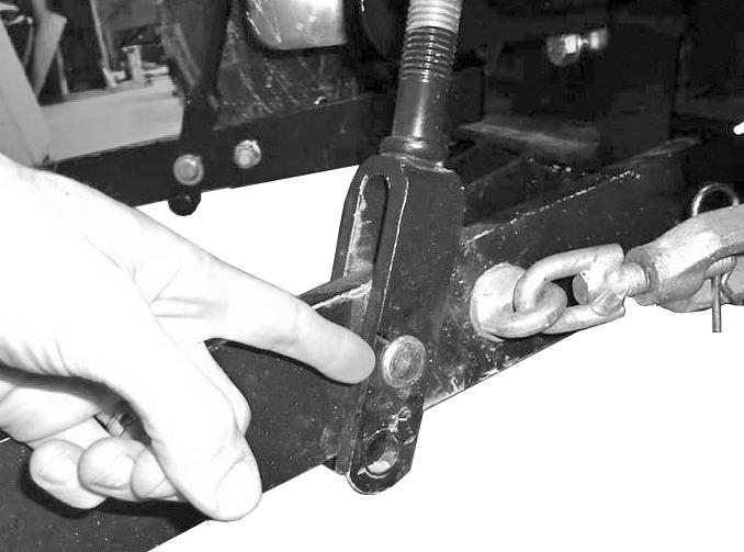
LIFT ROD SPRING CLIP REMOVAL (REVERSE STEPS TO ASSEMBLE)
LIFT ROD WITH ATTACHED SPRING PIN
11. Install the 3/4 x 3-3/4 inch Clevis Pin (22) in the 4 inch height of cut hole. Secure pin to bracket with Locking Ring (16).
NOTE: The pin in the height of cut hole (HOC) will rest on top of the draw bar when the 3-point hitch is lowered.
12. Figure shows rear lift components assembled.
13. Remount Rear Tires. See you Tractor Operator’s Manual or Technical Manual for wheel bolt torque values.
Mower Deck Adjustmentdeck Levelness And Pitch
1. Park tractor on level ground.
2. Check tire pressures, make sure tire pressures are equal on right and left sides of same axle.
3. Adjust lift link to top hole for lower Right and Left Hand Lower Draft Arms.
4. Start the tractor and slowly move the 3-point hitch control lever rearward until 3-point hitch arms are at full lift height.
5. Install the Clevis Pin in the 4 inch cut of height hole of rear height of cut (HOC) bracket assembly. Secure pin with Locking Ring.
6. Lower the 3-point hitch arms until the Clevis Pin in the (HOC) bracket is resting on top of the draw bar.
6. Place all four anti-scalp wheels in the middle hole position.
7. Adjust the spring pressure on the rear lift rods with the 1/2 inch flange head lock nuts to level the deck side to side. Increasing the spring pressure will raise the linkage and decreasing the spring pressure will lower the linkage.
8. To check and adjust side to side levelness, place a 2 x 4 inch piece of wood horizontally under the rear anti-scalp wheels. Adjust the nuts on the rear lift rods until you can slide the 2 x 4 under the wheel with wheel slightly touching.
NOTE: The adjustment of the nuts on the lift rods may be uneven to obtain the correct height adjustment.
9. To check front to rear pitch, rotate the left and right side mower blades until the blades are parallel (pointing front to back) with the tractor. Measure under the front and rear of the blade. The front measurement should be 1/8 inch lower than the rear.
10. To adjust front to rear pitch, support the front of the deck and unlatch front linkage from the front hanger brackets.
11. Loosen rear bolt (28) and move front bolt (28) to a different set of adjustment holes in both linkages as needed.
NOTE: Shortening the front linkage will raise the front of the deck and lengthening will lower the deck.
12. Re-latch the front linkage and check for proper mower deck pitch.
13. When the proper deck pitch is obtained, torque hardware.
NOTICE: When deck is properly adjusted, the anti-scalp wheels should never ride on the ground. After height of cut (HOC) is selected, the four anti-scalp wheel heights should be set so that there is a 1/2” space between the bottom of the wheel and the ground. If the wheels ride continuously on the ground, rapid wheel wear will occur.

