9 minute read
LUBRICATION


NOTICE: It is not recommended to use a pressure washer to clean the mower assembly. High pressure water may cause damage to spindles, pulleys, belts, or bearings shortening life and reducing serviceability.
Life of the mower depends upon the maintenance given. Proper lubrication is very important. Always lubricate the deck and lift components before operation.
Always wipe the fittings to be lubricated with a clean cloth before greasing. Dirt injected into the fitting will cause damage to the machined parts.
Use SAE Multi-purpose lithium base grease on all lubrication locations shown below. Remember to wipe away excess grease, which has built up around parts.
Lubricate grease fittings after every 50 hours of operation.
Miscellaneous working parts not provided with lubrication fittings should be oiled daily with a good grade of lubricating oil.
Cutting Height Adjustment
NOTICE: The Mower is to be operated with the front anti-scalp wheels and rear anti-scalp wheels above the ground.
The anti-scalp height is set by positioning the right and left wheels in one of three index hole settings. The hole settings range in 1/2” increments from a cutting height of approximately 2 inch (bottom hole) to 4 inches (top hole).
Initial Set Up
To initially adjust the deck, park on level ground and set the clevis pin to the 4 inch height of cut. Let the 3 point arms down so that the Clevis Pin of the HOC (height of cut) bracket is resting on the tractor draw bar. Have each of the anti-scalp wheels placed in the middle hole position. Place a 2 x 4 horizontally under each of the anti-scalp wheels. Tighten or loosen the nuts on the rear threaded links until you can slide the 2 x 4 under the wheel with wheel slightly touching.
After selecting the height of cut, the anti-scalp wheels are adjusted as follows.
Start the tractor and raise the mower deck to the upmost position by raising the three point hitch lever. Set parking brake, shut off engine and remove key.
WARNING – Use caution when adjusting deck cutting height. Block mower deck before proceeding with adjustment. The mower deck’s weight is supported by the tractor lift system. The deck could drop if the three point lift lever is accidentally shifted.
After determining the desired cut height as shown in the chart, and on the mower deck itself, adjust each anti-scalp wheel.
Remove Locking Ring and Clevis Pin from deck bushing. Align the hole in the wheel spindle with the hole in the deck bushing and install Clevis Pin. Secure with Locking Ring.
Repeat process for other three anti-scalp wheel spindles.
NOTE - Make sure the corresponding height hole setting is used in all four anti-scalp wheel settings.
Place the Clevis Pin in the corresponding desired cut height hole in the rear Hitch Plate Assembly at the rear of the tractor, near the draw bar and secure with Locking Ring.
Position Control Lever Stop Adjustment
Raise the mower deck until Up-stop is 1/4” from the bottom of the transmission housing. Adjust the Position Control Stop to set this as the maximum lift height.
NOTICE: Failure to make proper adjustment may result in damage to mower and/or dead heading and over heating the tractor hydraulic system.
MOWER BLADE REMOVAL, SHARPENING, AND INSTALLATION
DANGER Avoid Injury – A worn or damaged blade can break, and a piece of the mower blade could be thrown into the operator’s or bystander’s area, resulting in serious injury or death.
Never weld or attempt to straighten bent mower blades.
The mower blades must be kept sharp for a proper cut quality. Inspect blades before each use to make sure they are in good condition. Replace any blade that is damaged or worn.
Blade Removal
NOTE – Remove mower deck from tractor. Refer to “Mower Deck Removal From Tractor” section.
WARNING – Do not work under a raised mower deck unless it is securely supported by a hoist or jack stands.
WARNING – Avoid injury when handling blades as they are sharp, wear leather gloves or protectively wrap the blades.
Remove the blades using a 15/16” wrench to loosen bolt securing the blade.
A block of wood must be placed between the deck housing and the blade to assist in removal of the bolt.
Blade Sharpening
Sharpen the cutting edges of the blade evenly and at the same angle so the blades remain balanced. Unbalanced blades will cause excessive vibration, which could lead to gear box damage or damage to other mower components.
Check the blade for balance by centering the blade’s hole on a nail lubricated with a drop of oil. The heavy side of the blade will drop. Sharpen the heavy side until the blade remains balanced on the rod.
Sharpen the blade following the original blade angle. When using a grinder or grinding disk, use care such that the cutting edge does not get hot, causing the blade to lose its heat treatment. Loss of heat treatment will result in rapid blade wear and could fail in a hazardous manner. Do not sharpen to a razor edge. See diagram for proper method of sharpening.
If the cutting edge of the blade has had more than a 1/2” of the metal removed from sharpening or wear, the blade must be replaced.
Blade Installation
When reinstalling the blade note orientation, the “wing” must be pointing upward toward the top of the deck. Torque the bolt to 204 ft-lbs.
Check and re-torque the blade retaining bolt after the first hour of mower operation.
If the “air lift” area of the blade has eroded and a notch has developed and is 1/4” deep or greater, the blade must be replaced.
Belt Replacement
The mower deck belts should be replaced every 200 hours of mower operation, or anytime the belts shows signs of wear, cracking, or other damage.
NOTICE – The mower MUST be removed from the tractor for belt replacement. See “Mower Deck Removal” section for proper procedure.
Removal
Remove hardware securing the Right Hand Belt cover to the deck.
Remove hardware securing the Left Hand Belt cover to the deck.
Note the routing of the belt to help ensure proper installation of the new belt. Refer to belt diagram decal on deck.
Installation
Route the “backside” of the belt around the fixed Idler Pulley near Gear Box.
Route belt around Gear Box Pulley.
Route the belt around the Idler Arm Pulley. The “backside” of the belt will be making contact with the Idler Arm Pulley.
Route belt around the Left Hand Spindle Pulley.
Route the “backside” of the belt around the fixed Idler Pulley near Center Spindle.
Route belt around the Center Spindle Pulley.
Make certain the belt is properly engaged in each pulley, then place a “Breaker Bar” in the square hole provided in the Idler Arm. Carefully push the Idler Arm towards the left hand side, away from discharge opening to relieve tension. Slip the belt over the Right Hand Spindle Pulley, then carefully release the Idler Arm.
CAUTION – The Idler Arm with Idler Pulley are under spring tension. To prevent possible injury, use caution when handling the Idler Arm assembly.
Place a “Breaker Bar” in the square hole provided in the Idler Arm. Carefully push the Idler Arm towards the left hand side, away from discharge opening to relieve tension from the belt. Slip the belt off of the Right Hand Spindle Pulley, then carefully release the Idler Arm.
Remove the belt from the Center Spindle Pulley.
Remove the belt from the first fixed Idler Pulley.
Remove the belt from the Left Hand Spindle Pulley.
Remove the belt from the Idler Arm Pulley.
Remove the belt from the Gear Box Pulley.
Remove the belt from the second Idler Pulley.
Remove the belt from the deck and discard.
Reinstall Right Hand and Left Hand Belt covers to the deck.
Gear Box
Make sure the mower deck and tractor are located on level ground for service. The correct oil level will be filled to the drive shaft center line.
CAUTION – Prior to operation, make sure the gear box contains the correct amount of oil (6 ounces). If under filled or overfilled, damage to the gearbox or personnel injury may result.
Approved lubricants for units operating in ambient temperatures up to 125 degrees Fahrenheit, and oil temperatures to 200 degrees Fahrenheit is “Mobilube HD80W-90” (or equivalent) is recommended. For gear drives operating continuously above 200 degrees Fahrenheit, “Mobilube synthetic SHC 75W-90” (or equivalent) is recommended.
NOTICE: Do not combine synthetic with nonsynthetic oils in the gearbox.
The lubricant level should be checked each 24 hours of operation. After the first initial 50 hours of operation, drain the oil and refill to the proper level. Thereafter, oil changes should take place after every 250 hours of operation.
Remove plug located on side of gear box located on the side opposite of the fixed Idler Pulley.
Correct oil level is to the center line of the drive shaft.
DISASSEMBLY
Remove the mower from under the tractor and prepare it for gearbox removal.
1. Remove all fasteners retaining the mower gearbox brackets to the top of the deck and remove the gearbox assembly.
2. Loosen and remove the collet hub and pulley from the output shaft on the gearbox.
3. Remove the bracket(s) from the gearbox. Remove both side pipe plugs, lay the box on one side and drain all old oil.
4. Remove all eight socket head bolts securing the gearbox halves together. Tap the seam with soft wood or plastic hammer to break the seal. Lay the gearbox on its side and remove the top half. The top half contains thru holes.
5. Lift both shafts from the case and completely disassemble the gearbox. Remove old sealer from both housing halves, wash parts in a clean solvent and inspect for signs of excessive wear or damage.
REASSEMBLY
1. Place both shaft assemblies in the bottom case half, identified by the threaded holes. Make sure all parts are correctly positioned, especially the seals. The pinion shaft seal must be against the front lip of the casting.
NOTICE: DO NOT allow liquid gasket material to get into the seal recesses in the housing.
2. Apply a 1/16 inch (1.6mm) bead of Locktite Number 515 liquid gasket material to the flat surface of the bottom case half only.
3. Place the cases together, insert and torque the socket head bolts to 15-20 ft. lbs (20-27 Nm). Lightly tap the shaft ends with a soft hammer to seat the bearings against the retaining rings.
4. Position the gearbox with output shaft pointing up, as it will be on the mower and fill it with oil.
5. Reinstall the mount brackets to the gearbox. Replace the gearbox and bracket assembly on the mower deck with its removed fasteners. Install the pulley and collet hub on the output shaft on the gearbox. The collet hub and pulley must be set at the 1-9/16” dimension to maintain proper belt clearances. The collet hub will move slightly as it is tightened, check dimension.
Gearbox Service Parts Breakdown
*PARTS SUPPLIED WITH GEAR BOX SERVICE KIT 015286, OTHER COMPONENTS ARE NOT SERVICEABLE. FOR COMPLETE GEAR BOX, ORDER PART NO. 015285

Common Mowing Problems
Streaking
Streaking is when thin strips of uncut grass are left behind the mower. Streaking is usually caused by operator error or poor blade maintenance.
Cause Solution
Blades are not sharp.
Sharpen your blades.
Blades are worn down too far Replace your blades.
Engine speed is too slow. Always mow at rated PTO engine speed.
Ground speed is too fast. Slow down.
Deck is plugged with grass. Clean out the mower. Not overlapping cutting rows enough. Overlap your cutting rows.
Not overlapping enough when turning. When turning your effective cutting width decreases - overlap more when turning.
Stingers
Stingers are sparse patches of uncut grass left behind the mower. Stingers are usually caused by operator error or poor blade maintenance.
Cause Solution
Blades are not sharp or are nicked. Sharpen your blades. Blades are worn down too far. Replace your blades.
Engine speed is too slow. Always mow at rated PTO engine speed.
Ground speed is too fast. Slow down.
Deck is plugged with grass. Clean out the mower.
Common Mowing Problems
Uneven Cutting
Uneven cutting is waviness or smooth troughs in the law surface. Uneven cutting is usually caused by mower deck damage or mis-adjustment..
Cause Solution
Deck is not leveled correctly. Level the deck correctly.
Blades are dull or worn. Sharpen or replace the blades.
Blades are damaged. Replace the blades.
Deck is clogged with grass clippings. Clean out the deck.
Deck shell is damaged. Repair or replace the deck.
Mower spindle is bent or loose. Repair or replace the spindle.
Blades are installed incorrectly. Reinstall the blades correctly.
Scalping
Scalping is when the mower deck comes close to or hits the ground. Scalping can be caused by the mower deck misadjustment, unevenness in the lawn, or by mower deck bouncing because the ground speed is too fast.
Cause Solution
Lawn is uneven or bumpy. Roll or level the lawn.
Mower deck cutting height is set too low. Raise the cutting height. Ground speed is too fast. Slow down.
Deck is not leveled correctly. Correctly level the deck.
Tire pressure is low or uneven. Check and inflate the tires.
Common Mowing Problems
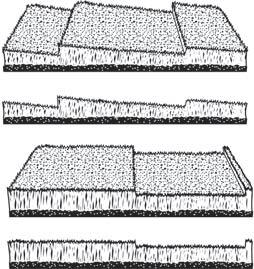
Stepped Cutting
Stepped cutting is sharp ridges or uneven levels left in the lawn surface. Stepped cutting is usually caused by mower deck damage or mis-adjustment, or damage to mower blades.
Cause Solution
Deck is not leveled correctly. Level the deck correctly. Tires are not properly inflated Check and inflate the tires. Blades are damaged. Replace the blades. Deck shell is damaged. Repair or replace the deck. Mower spindle is bend or loose. Repair or replace the spindle. Blades are installed incorrectly. Reinstall the blades correctly.

