26 minute read
BLEEDING THE FUEL SYSTEM


1) Fuel filter cock 「 ON 」
2) Open the cock on the fuel injection pump.
3) Fill the tank with fuel and turn the ignition key to on.
4) Start the engine and allow it to run for a while.

5) Close the fuel injection pump cock.
6) The bleeding of the system is now finished.
Changing The Oils In The Tractor
Always use quality oils as engine or transmission oil (refer to page 63, 64)
Refer to the table on page 57,58 and 59 for the change frequency.
▶ Changing engine oil. Park the tractor on a level surface, shut-off engine. Remove sump plug & drain oil. Replace and check the sump plug and refill the engine with oil to the correct level on the dipstick (approx. 1.85 gal).
The grade of oil to be used will depend on the ambient temperature. (API CJ-4 grade)
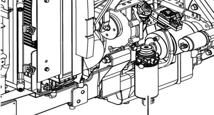
Fuel Filter
Thetractorisshippedfromthefactorywith10W/30
The tractor is shipped from the factory with 10W/30
For summer use over 77℉ use SAE 30
For temperatures from 32℉-77℉ use SAE20 or 10W/30
For temperatures below 32℉ use SAE 10W
Engine Oil Filler
Engine Oil Filter
Engine Level Gauge
When changing the oil always change the filter. Always use the same oil, as using different oils or specifications can cause damage. Dispose of the old oil as per local regulations. Important
► CHANGING THE TRANSMISSION OIL
Remove the drain plug from the bottom of the transmission and drain the oil. Replace and check the drain plug.
Refill the transmission to the correct level on the dipstick with new oil : Qty 35ℓ(9.24 US gal)
Always use the same grade and specified oil as replacements. Dispose of the old oil as per local regulations. Important
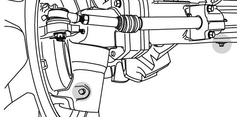
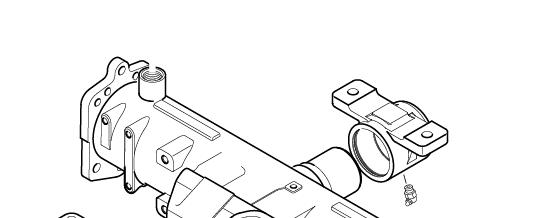
► CHANGING OIL IN THE FRONT AXLE
1. Drain the oil from the center diff plug and the drain plug in each drive.
2. Replace and tighten all drain plugs.
3. Remove the top plug (Vent plug) from each final drive to vent air from final drives.
4. Remove the dip stick from the filter hole and fill with 2.64 US gal (10 liters) and allow time for the oil to drain into the final drives.
5. Check the oil level with the dipstick and replace the vent plugs on both final drives and tighten.
Level gauge & Oil Filler
Some operators have found that when they fill with the correct amount of oil and check, the oil level on the dipstick is too high due to the fact that it takes a while for the. oil to run into the final drives.
Important
Oithtlhltdthi
Opening the vent plugs helps to speed this up.
CLEANING AND CHANGING FILTERS
► ENGINE OIL FILTER
Using a filter wrench, turn the filter counter clockwise to remove it.
Lightly smear the rubber seal on the new filter with oil to ensure, turn it clockwise until the seal contacts the base and then turn it another 2/3 turn to tighten it.
Engine Oil Filter
► FUEL FILTER
The fuel filter/water separator (if equipped) is not usually supplied by Mahindra.
The following test describes a typical fuel filter/water separator. Refer to the OEM information for further information in the fuel filter/water separator. Turn the fuel supply valve (if equipped) to the OFF position before performing this maintenance. Place a tray under the fuel filter in order to catch any fuel that might spill. Clean up any spilled fuel immediately.
1. Close the fuel supply valve (if equipped).
2. Clean the outside of the fuel filter assembly.
Fuel Filter
Note: If the fuel filter element is not equipped with a drain, remove cap. Remove the nylon insert in order to reduce the level of fuel in the fuel filter element. A reduction in the level of fuel in the fuel filter element will help prevent fuel from being spilled when the element is removed.
Notice: Do not use a tool in order to remove the fuel filter. Attempting to remove the fuel filter with a filter wrench or a filter strap could damage the locking ring.
3. Hold the fuel filter and rotate the quick release collar counterclockwise. Remove and discard.
Note: If the element is equipped with a sediment bowl, remove the sediment bowl from the element. ThhllthditblItthO il Thoroughly clean the sediment bowl. Inspect the O-ring seals. Install new O-ring seals, if necessary. Install the sediment bowl to the new element. Hand tighten the sediment bowl. Hand tightening is the only method that should be used. Notice: Do not fill fuel filters with fuel before installing them.
Contaminated fuel will cause accelerated wear to fuel system parts.
4Ensurethatthefuelfilterbaseisclean
4 Ensure that the fuel filter base is clean
Push a new fuel filter fully into the fuel filler base.
5. Hold the fuel filter in place.
Fit the locking ring into position.
Rotate the locking ring clockwise in order to fasten the fuel filter to the fuel filter base.
6. Open the fuel supply valve (If equipped).
Never use petrol (gasoline) thinner or similar flammable material to wash the primary fuel filter.
After replacing the filter always bleed the system Important
► HYDRAULIC OIL FILTER AND ENGINE OIL FILTER CARTRIDGE hfilihfilh
Remove the filter with a filter wrench
To replace, apply oil or grease to the seal, fit by hand until seal contacts bare, then turn it a 2/3rd turn further to tighten it, check for leaks.
Changing The Coolant
(1)Open the tap in front of the gear pump to drain the coolant.
(2) Open the radiator cap at the same time. pp
(3)To give a thorough clean, run a hose into the radiator and flush it out.
(4)Close the tap and refill the radiator with a coolant mixture of water and corrosion inhibitor or anti freeze.
(5) Start the engine and allow it to run for approx 5 minutes, check the water level again and top off if required.
Caution
Donotremovetheradiatorcaponahotengine.
Allow the engine to cool down and then turn the cap slowly to ensure, that there is no excessive pressure in the radiator.
Seriousburns,canresultfromthecontentsofpressurized,hotradiators. Allow the engine to cool down completely before opening the radiator.
Caution
► ANTI FREEZE
Frozen cooling water can damage the engine. Before replacing the anti freeze solution, flush the radiator. Mix the anti freeze solution in accordance with the instructions applicable to the brand of anti freeze and the local climate. Replace the solution in the radiator.
In the case of the loss of solution due to evaporation or overflow, replace with the original mixture ratio.
► CLEANING THE RADIATOR
Insects, grass, straw and dust can all block the radiator, or condenser and reduce their efficiency. Remove the radiator screen to clean it and the radiator. Release the bolt and pull to remove the screen. Then clean the radiator between the fins and tube by using clean water.
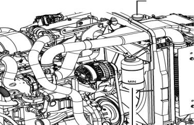
Reservoir Tank
Greasing The Tractor
Grease the tractor according to the service schedule (page 56,57 and 58.)
Ensure that grease nipples are cleaned well before any attempt is made to grease them.

Gap Adjustment
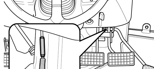
Adjusting The Clutch
Using the clutch over a period of time will increase the free play.
Thecorrectfreeplayofthepedalis0.78 1.18in The correct free play of the pedal is 0.781.18 in To adjust, loosen the locknut on the turnbuckle and adjust.
Check the adjustment and tighten the locknut if the free play is correct.
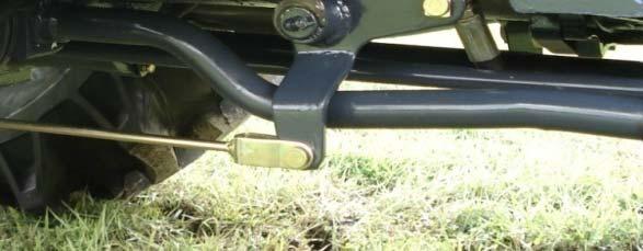
Adjusting The Brakes
As is the case with the clutch, use of the brakes will change the pedal free play and the balance between the right and left pedal.
The correct pedal free play is 1.18~ 1.57 in
Adjusting Method
Loosen the locknuts to adjust the brake. Turn counterclockwise to increases the free play, or turn clockwise to decreases.
Tighten the locknut and confirm to fix the Nuts. Check that the free play is correct and the same on both pedals to ensure even braking
Uneven adjustment of the left and right pedal will result in one sided braking when the pedals are connected and can cause serious accidents, especially at high speeds.
Doublechecktoensurefreeplayisthesameonbothpedals Caution
ADJUSTING THE THROTTLE LEVER
If this lever is either loose or difficult to move please consult your dealer for rectification of the problem.
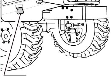
ADJUSTING TOE-IN
If the toe-in adjustment is incorrect it can cause severe shaking of both the steering wheel and the entire tractor.
The correct toe in is 0.08~0.24in. We recommend that this adjustment is made by the dealer.
CHECKING THE BATTERY
Check the Indicator condition Indicator condition
Green color –Good condition
Black color –Charging needed
White color –Replace battery
Low electrolyte levels can cause premature battery failure and corrosion. Important
Electrolyte contains acid and can cause serious burns. Any spillage on skin should be washed off by running water immediately ypgygy Caution
► BATTERY MAINTENANCE
Low temperatures will affect the performance of batteries so take particular care of it in winter. For long-term storage of the tractor, remove the battery and keep it in a cool dry room. If it is on the tractor while stored, disconnect the negative terminal. Batteries will self discharge if left for a period of time without use.
Tokeepthemingoodconditionchargethemonceamonthinsummerandeverysecondmonthin
To keep them in good condition charge them once a month in summer and every second month in winter.
When replacing the original battery, ensure that the replacement battery is the same size. Failure to do so can cause problems with the electrical circuit.
► BATTERYCHARGING
BATTERY CHARGING
-A boost charge is only for emergencies.
It will partially charge the battery at a high rate and in a short time.
-When using a boost-charged battery.
It is necessary to recharge the battery as early as possible. Failure to do this will shorten the battery’s service life.
Always disconnect the negative terminal first when removing the battery and always connect the positive terminal first when fitting the battery. When connecting the battery leads make sure not to reverse the polarity. Quick charging will reduce battery life.
Ditthtilithithbtttiddtth Caution Disconnect the terminals prior to charging the battery to avoid damage to the circuit and electrical instruments.
Fan Belt Adjustment
1.Loosen the alternator pivot bolt.
2Mthlttidti
2 Move the alternator in order to increase or decrease the belt tension.
Tighten the alternator pivot bolt and the link bolt to 22 N.m(16 lb ft)(1)
0.28~0.35inch
Alternator Inspection
Mahindra recommends a scheduled inspection of the alternator.
Inspect the alternator for loose connections and proper battery charging.
Inspecttheammeter(Ifequipped)duringengine Inspect the ammeter(If equipped) during engine operation in order to ensure proper battery performance and/or proper performance of the electrical system.
Make repairs, as required.
Check the alternator and the battery charger for proper operation.
If the batteries are properly charged, the ammeter dihldb
(1) Burroughs gauge. reading should be very near Zero. All batteries should be kept warm because temperature affects the cranking power.
If the battery is too cold, the battery will not crank the engine.
When the engine has not been run for long periods of time or if the engine is run for short periods. The battery may not fully charged.
Fit the gauge (1) at the center of the longest free length and check the tension.
The correct tension is 535N (120 lb).
If the tension of the belt is below 250N (56 lb) adjust the belt to 535 N (120 lb).
If twin belts are installed, check and adjust the yg more easily than a battery with a full charge.
A battery with a low charge will freeze
Alternator and Fan Belts Inspect/Adjust/Replace
For applications that require multiple drive belts, replace the belts in matched sets.
tension on the both belts. Replacing only one belt of a matched set will cause the new belt to carry more load because the older belt is stretched.
The additional load on the new belt could cause the new belt to break.
If the belts are too loose, vibration causes unnecessary wear on the belts and pulleys. A loose belt may slip enough to cause overheating. Toaccuratelycheckthebelttensionasuitable
To accurately check the belt tension, a suitable gauge should be used.
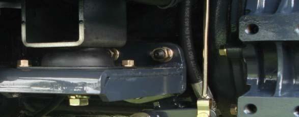
Air Conditioner Compressor Belt Adjustment
Check the compressor belt tension regularly and adjust if required.
The correct tension is when the center of the belt is pushed with a finger and it moves in approx. 10mm(039in)asshowninthepicture
10 mm (0 39 in) as shown in the picture
To adjust the belt, loosen or tighten the nut as shown in the picture.
Servicing The Air Cleaner
To remove the dust from the evacuator valve, squeeze it between the thumb and fingers to let excess dust out and wipe around the valve to keep it clean from outside.
To clean the main element, remove the right fan cover. Remove the element by unloading the wing nut. Remove dust by blowing it out of the element with compressed air.
Check the element to ensure it is not damaged. Reassemble the element.
Never beat the element on a stone or concrete floor/wall to clean it Check all connections and hoses especially on the clean side of the air cleaner to ensure no dusty air can enter the engine.
Check the element for flaws by putting a light inside the element. When reassembling make sure all surfaces seal correctly to keep dust out. When working in dusty conditions increase the service frequency. Important
▶Replace the element after cleaning it 5 times or if is damaged.
Checking Hoses And Lines
The fuel lines, radiator hoses, hydraulic and rubber hoses are consumables, which deteriorate by age and use.
Check them regularly and replace if faulty.
Damaged fuel lines leak and cause fires.
Damagedradiatorhosescancausehotwaterburnsandinseverecasesseizethe engine. Caution
CHECKING THE WIRING HARNESS AND FUSES
Loose wires make inferior connections and damaged wires can cause short circuits, fires burnt wiring or reduce the efficiency of components.
Replace or repair any faulty wiring or insulation.
If a fuse burns out again after it has been replaced, do not replace it with wire or a high capacity fuse, fidthdtifitttltiitd find the cause and rectify it or get an auto electrician to do so.
Where insulation is chafed or peeled off, recover the area with a good quality insulation tape. Where wiring comes out of it’s fitting, replace it correctly with the standard fitting.
Incorrect wiring or fuses can cause fires to both the tractor and surrounding area so get the dealer to check it annually.
Likewise fuel pipes and wiring age with use.
Askyourdealertocheckitatleastonceevery2yearsandreplaceasrequired
Important Ask your dealer to check it at least once every 2 years and replace as required
► REPLACING FUSES
The circuit has 8 blade type fuses in its wiring circuit
(See diagram on page 99).
When a fuse has blown, replace it with one of the same value. Using a large capacity fuse or wire burns out the wiring system. Use fuse tongs to replace fuses.
► MAIN FUSES
The wiring harness is equipped with 3 main fuses whose function is to preserve the wiring.
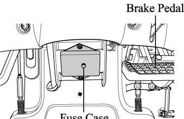
However, when a main fuse blows the entire circuit is dead. Always check the reason & rectify before replacing with a fuse of the same value.
To indicate that the fuse is blown it will be discolored.
Always check the reason for a blown fuse otherwise the new fuse is also likely to blow.
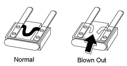
Important
NEVER EVER USE WIRE in place of a correct grade fuse.
SERVICE PRIOR TO DAILY AND SHORT TERMS STORAGE.
Wash the tractor and keep it clean.
Fill the tank to avoid condensation and rust.
Lower any attached implement to the ground before parking the tractor. For long-term storage consult your dealer.
3. MAINTENANCE
For daily or short term storage owetepeettotegoud..
Clean the tractor and remove all dirt from field work. Fill the fuel tank to avoid condensation and rust. Lower the implement to the ground..
Keep it in a machinery shed or, if not available cover the unit if left outside. In very cold conditions it is advisable to remove the battery and keep it inside in a warm environment. This will ensure effective starting when the tractor is required.
When the outside temperature is below 32℉, replace the antifreeze completely or drain the coolant to protect the engine from damage from frozen coolant.
Important
When washing the tractor ensure that the water does not get near electrical gg components or the oil filter points.
To prevent short circuits remove the ignition key. Do not wash the tractor when the engine is running.
Long-term storage.
When the tractor will not be used for a long time, carry out the cleaning as for short term storage. Drain the oil and replace with new oil.
Run the engine for approx. 5 min. to ensure that it has new oil throughout the engine. Drain the coolant from the radiator and remove the ignition key.
Attach a tag to both the key and the steering wheel saying” No coolant”. Lubricate all grease and oil points on the tractor.
Check the pressures and add a small amount of extra pressure. Lower any implement to the ground or store in a shady dry place. Disconnecttheclutchbyusingtheclutchdisconnectingarm.
Disconnect the clutch by using the clutch disconnecting arm. Place a piece of wood under each tire to preserve the tire. Important eovetegtoeyadstoeasaepace.
After refilling the engine with the coolant run the engine for approx. 5-10 min. at 1500-2000rpm every month as a corrosion prevention measure. Either remove the battery or the negative terminal as mouse damage to wiring can cause short circuits and fires. Remove the ignition key and store in a safe place.
Re-use after long term storage.
Carry out a full check of all oils and coolant.
Refit the battery and run the engine at idle for 30 min. to ensure optimum engine life.
Section -C CABIN
Thecabfullyconformstotheinternationalstandardasfarassafetyandsoundproofingareconcerned. The cab fully conforms to the international standard as far as safety and soundproofing are concerned. It can be provided with ventilation, heating and air-conditioning systems. It is available in the following version.:
● Cab with ventilation and heating systems
● Cab with ventilation, heating and air-conditioning systems.
The cab is in full conformity with the international standards as to the cab’s soundproofing.
Be very careful when operating in small spaces and always protect your ears whenever other working equipment is generating dangerous noise levels.
Working Lamp
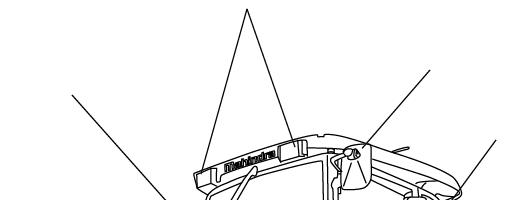
Rear Mirror
Rear Mirror
Door Handle
Remember that steering, braking and operational performances are highly influenced by the implements mounted, the trailers transported and the ballasts applied to the tractor.
When transporting heavy loads (exceeding the weight of the tractor) reduce the speed under 15 Km/h.
All the implements mounted onto the tractor must be safely secured.
BeverycarefulduringimplementhitchingandunhitchingoperationsWhenusing
Be very careful during implement hitching and unhitching operations When using implement supports, be sure they are suitable and sufficiently strong.
► INSTRUMENT AND RELATED PARTS
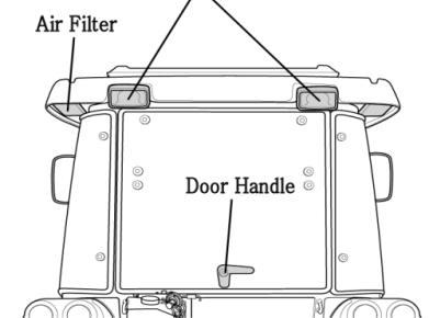
■ Doors: The doors are provided with key locks.
To open from the outside, when unlocked, depress the push button. To open from inside, push the lever downwards.
■ Rear Window:
The rear window is fitted with a central handle for opening.
Whenopeneditisheldinplacebytwodampers When opened it is held in place by two dampers
■ Side Window:
The side window is fitted with a central handle for opening. Whenopeneditisheldinplacebyaholder. When opened it is held in place by a holder.
■ Working lamps (front and rear) : The working lamps are located on the cab roof (two in the front and two in the rear) . They are switched on by means of the special switches on the roof console.
■ Rearview mirrors.:
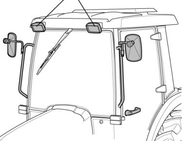
The cab is provided with rearview mirrors on both sides. They can be adjusted and folded, whenever necessary, to avoid interference with external obstacles. The mirrors have a telescopic arm to allow positioning for maximum convenience by the user. Remember that mirrors must always be positioned in compliance with road traffic regulations when driving on a public highway.
■ Cab ceiling:
The ceiling is padded with insulation material to block heat radiation into the cab and keep the temperature down when working in very sunny areas.
The cab platform is covered with a “firm grip” carpet in the most commonly used areas.
It is recommended to keep this carpet clear of earth, mud, etc. so that the operator may get on and off the tractor in full safety.
► How to Controls the Cabin
Ventilation
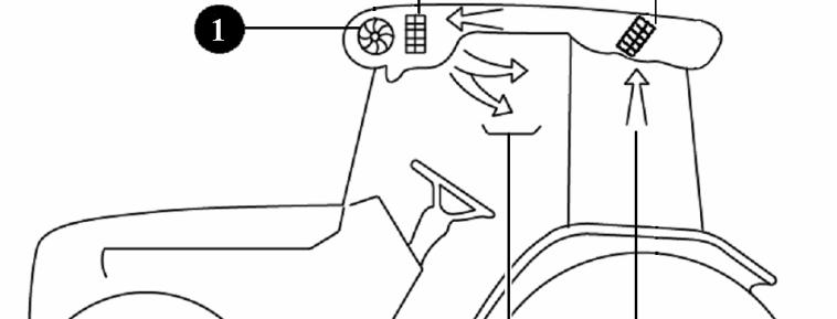
The ventilation unit is housed in the cab ceiling.
To switch it on and adjust it, turn the electrical fan switch to the desired speed. The cab becomes slightly pressurized when the ventilation system is in operation, so that fresh air can enter only by way of the filter installed in the rear section of the cab roof. Thefanswitchcanbeoperatedonlyaftertheignitionkeyisinserted. The fan switch can be operated only after the ignition key is inserted. The air flow can be regulated and directed by suitabley positioning the air diffusers. Air can be taken in fresh from outside or recycled from within the cab by way of the relative side inlets.
■ Re circulationInlets fully closed:
Air is taken in entirely from outside the cab through the rear grille and filtered through a paper element positioned behind the grille.
N.B-it is very important that the air diffusers never be completed closed so as to allow for a steady air flow.
To obtain a greater pressurization inside the cab, it is necessary to take air from the outside, therefore the inside air recirculatiing grille should be fully closed.
■ Working Lamp Switch
The front and rear working lights are ON when the button is pushed. The work light indicator lamp on thilillilli he instrument cluster will illuminate.
■ Wiper control switch
-Switch ON
The Wiper switch is ON when the Top button is pushed. The Washer switch is ON when the Mid-button is pushed.
-Switch OFF
Onceagainpushthebuttons Once again push the buttons
■ Windscreen Washer Tank
Check the level of windscreen washer fluid in the plastic reservoir located at the front of the radiator. During winter, it is advisable to add a suitable antifreeze or methyl alcohol to the windscreen washer fluid.
■ Interior Lamp
Push the button to turn the light on and push it again to turn the light off.
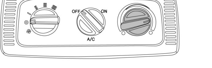
■ Blower Control Switch
Three position rocker switch
■ Temperature Control
Set temperature control as required,fully clockwise for maximum cool and fully counterclockwise for heat.
Temperature Control
■ Air Con. Switch
To operate the air conditioner, the blower must be on.
The blower speed temperature control and all vents must be adjusted to obtain the best cooling for the ambient temperature and dust conditions.
Under normal operating conditions, and with the windows and doors closed, temperatures in the cab of 6ºC to 15 ºC (10 ºF to 25 ºF) less than the ambient temperature will occur. When operating the air conditioner system, the moisture level is decreased.
NOTE:
1) During cold weather, with ambient temperature above 0 ºC (32 ºF) operate the air conditioner at least once per month, for a period of 10 to 15 minutes. This will lubricate the seals to prevent them from becoming brittle and help to prevent the loss of refrigerant from the system.
2)ThesystemisequippedwithanenvironmentallysaferefrigerantR134a
2) The system is equipped with an environmentally safe refrigerant, R134a. Never recharge the air conditioning system with refrigerant other than R134a as this will result in loss of cooling and permanent damage to all air conditioning components.
■ Circulation Diffuser
With the circulation vent set in any position, Outside air will still be pulled into the cab.
Heating System
General description
The heater is switched on and adjusted by rotating the control knob at the roof console, then switching on the blower and setting the selector to at the preferred speed . To warm the cab up quickly, the knob should be rotated fully clockwise and the blower set to speed 3. The screen is demisted or defrosted by air directed through a slot vent. For defrost or fast demist, all other vents should be closed off.
IMPORTANT:
Ventilation is provided by a single blower unit serving both the heating system and the air conditioning system.
After reaching the desired temperature, adjust the system to suit your needs.
NOTE:
-For ideal system operation, the engine must run at 1000 rpm
Warning
Before starting the engine, make sure the system is off (by turning off the ventilation fan) so as not to overload the battery. After the system is at full power for a long period of time, never turn it off suddenly but let it first idle for about 20 seconds.
System Configulation
1.The heating system consists of two units:
1-Electric heater and blower unit installed behind the roof console.
2-Power supplying set, consisting of an auxiliary alternator located in front of the engine and driven by a belt directly linked to the engine pulley. ddvebybedecyedoeegepuey.
If the air does not come out from the diffusers right away as soon as the system is started, turn it off immediately and identify the fault.
N.B-Never turn on the heating system when working in dusty environments.
■ Compressor Belt Adjustment
Check the compressor belt tension regularly and adjust if required.
The correct tension is when the center of the belt is pushed with a finger and it moves in approx. 10 mm (0.39 in) as shown in the picture.
To adjust the belt, loosen or tighten the nut as shown in the picture.
Air Conditioner System
The system is designed to ensure optimum temperature inside the cab and maximum comfort and safety for the operator.
However, it is advisable to consult our specialized workshops whenever repairs or adjustments need to be performed.
Do not approach the system with open flames, as any escape from the circuit may produce a lethal gas.
■ Roof hatch (if equipped)
Ventilation Push the latch towards the front of the tractor and then push the hatch up.
Emergency Exit Push firmly upwards to release the supportstrutsfromthelowerretainerclips. support struts from the lower retainer clips.
■ Circulation Diffuser
With the circulation vent set in any position, Outside air will still be pulled into the cab.
■ Radio, CD player ( If equipped)
For operation refer to the Radio, CD player manufacturers instructions.
■ Ash tray
Located at the right side of the near side window in the cabin.
■ Cup Holder
For bottles and personal belongings.
■ Cigarette Lighter
Push the button. Use after it retune to its original position.
1. Checking the air conditioning system.
①environment friendly refrigerant : R134a 0.7∼0.85Kg. The presence of air and water in the system could jeopardize its efficiency.
-The air is uselessly compressed by the compressor and no cooling effect is produced.
-Themoisturehasatendencytorisetoobstructionswhichpreventthecoolingefficiency. The moisture has a tendency to rise to obstructions which prevent the cooling efficiency.
② Check belt tension ; when finger pressure is applied to the mid-point between both pulleys.
③ Condenser fins must always be duly clean using water or an air set.
2. Checking the air conditioning system charge
(1) Check the refrigerant charge.
ARuntheengineat1500rpm
A Run the engine at 1500rpm
B.Set the air conditioning system to the coldest for 5 minutes.
C. Check the sight glass clear or cloudy.
If the air-con. is operated without being charged. Caution pgg the lubrication in the compressor can cause damage.
(1) Check the refrigerant via the receive drier sight glass
Bubbles or foam visibleTrouble shoot
● Bubbles flow and refrigerant gas disappears like a fog
● Same bubbles appear occasionally (1~2 sec. gap)
● Dfiitffit
Deficient of refrigerant Replenish
● Nothing different temperature between H.L pipe
● High pressure of the pressure gauge needle indicates low pressure.
● Replenish the refrigerant
● High pressure pipe is hot and low pressure pipe is a little cool.
● H.L pressure of the pressure gauge needle indicates low pressure.
Abnormal
Abnormal
Bubbles or foam visibleTrouble shoot
● No bubble shown High-pressure pipe is abnormally hot. abnormally.
●Too much refrigerant deflate.
●High pressure pipe is not abnormal
● H.L pressure of the pressure gauge needle indicates high abnormally.
Abnormal pressure gauge needle indicates abnormally high pressure.
H-L pressure of the
● Refrigerant in the sight is shown clear.
● When engine RPM operates with high low. some bubbles disappear
● Normal refrigerant gas situation
● High pressure pipe is hot. Low pressure pipe is cool.
● High low pressure is normal with below.
Abnormal slowly
Low: 1.5~2.0kg/㎡
High: 14.5~15 kg/㎡
3.Diagnosing malfunctions.
(1) Tracing faults
SYMPTOMCONDITIONCAUSEREMEDY
Insufficient Lub.Replenish
1.Compressor
Abnormal sound Inlet sound Outlet sound
Belt tension releaseAdjust
Release the bracket Tighten the bolts
Clutch failCheck
Damaged partsCheck,replace
Abnormal revolution Inlet cause gp ,p Slip the clutchCheck,replace Not Lub.Replenish Outlet causeBelt tension releasedAdjust
Sealing washer damaged replace Tightenthe oil leakage oil leakage Head bolt released Tighten the bolts
Refrigerant or oilleakage Refrigerant or
D-ring damagedReplace
Excessive pressure Low,High pressure Insufficient refrigeratorAdjust CompressorReplace
2.Motor
Symptomconditioncauseremedy
Motor is normal
Air inlet cloggedRemove Evaporator freezing Controlling minimum pressure
Weakfrom
Ventilator switch Replacetheswitch
Weak from pressure or Doesn’t work damage Replace the switch CompressorReplace Motor is abnormal Motor failureReplace Wire cutReplace Air leakageDuct leakageCheck,tighten
Unableto Motor Air volume control switchfailure Check,tighten Unable to control the fan switch failure Motor is abnormal Motor failureReplace
Noise Regular noise Irregular noise Interference with pulley Control the compressor direction
Engaged sometimes Wire defectCheck wire
3.Clutch Disengage Engaged to push with hand
Clutch gap largeAdjust Low voltageCheck battery No defect wiremalfunctionReplace
Slip Slip during rotation
Low voltageCheck battery Oil stick at clutchClean
MalfunctionReplace
(2) How to check the air conditioning system with the needle of high low gauge
Via the connection of the manifold pressure gauge, one can monitor the air conditioning system. Because the manifold pressure gauge varies sensibly (Ambient Temp. is based on 30~35℃)
Caution:
Operating E/G RPM 1500~2000 is a must, so to that you can check the correct cause and air conditioning.
(As in the below the figure of indicated pressure, the gauge has some clearance, confirm with the (gp,gg, Approximatein dicated needle data.)
Gauge pressure conversion
● lb/in²=PSI
●1 kg/㎠=14,223 in²
(Ex) 200 PSI=14 kgf/㎠
Section -D
Specifications
The specifications on the following pages are given for your information and guidance. For further information concerning your tractor and equipment, consult your authorized Mahindra dealer/ distributor.
Mahindra. policy is one of continuous improvement and the right to change prices, specifications or equipmentatanytimewithoutnoticeisreserved. equipment at any time without notice is reserved.
All data given in this book is subject to production variations.
Dimensions and weights are approximate only and the illustrations do not necessary show tractors in standard condition.
For exact information about any particular tractor, please consult your Mahindra authorized dealer/distributor.
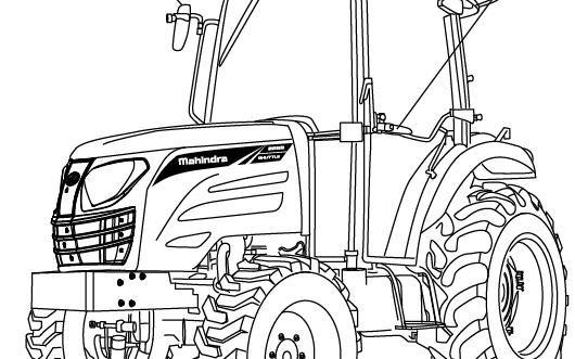
Specifications
Model: 2555Shuttle/ Shuttle Cab
ENGINE
FourstrokesIndirectinjectionwater cooled
CLUTCH T Dih Four strokes, Indirect injection, waterDiesel Engine.
Model : Tier-4 5530
No. of cylinders : 3
Displacement(cc) : 2,648cc
Bore (in/mm) : 3.8 in /96mm
Stroke (in/mm) : 4.8in /122mm
Compression Ratio : 17.2:1
Rated power (HP) : 55/2300 rpm ype : Diaphragm
Outer dia. X Inner dia. : Ф260XФ180
TRANSMISSION
Type : Constant
No. of gears :12 forward, 12 reverse speeds with high and low selection lever with Differential Lock
(fii)
(Manufacturing rating)
Rated Speed : 2,300rpm
High idle rpm : 2,500±50RPM
Low idle rpm : 850 ±50
Fuel injection type : Common Rail.
Cylinder sleeve : -
Air Cleaner : Wet Filter element, paper element filtering type.
Exhaust Muffler : Horizontal External type
Firing order : 1-3-2
Accelerator : Hand & Foot Accelerator
ELECTRICAL STARTING AND LIGHTING
Battery Capacity : 12 Volt 100AH
Starter : Solenoid Engaged. Key Start with interlock, Neutral switch
STEERING : Hydraulic power (Power steering)
POWER TAKE OFF
Rear mounted : 6 splines
Diameter : 1⅜ in.(35mm)
Standard PTO : ① 540
BRAKES
Foot operated, independent with provision of p,pp inter lock for simultaneous operation. A foot brake is fitted for parking.
Disc Diameter :Φ183mm(Φin)
Number of lining :4 each side
Total brake thickness : 21.1㎜(in.)
HYDRAULIC SYSTEM
Alternator:12V90A
Alternator : 12V 90A
Instrumentation : Water Temperature Gauge, Taco meter, Hour meter, Electrical fuel level gauge.
Lighting: Head lamps, side indicators, Rear parking brake & indicator light
On dash board indicators fbtthit for battery charging, turn signal, PTO signal, Engine oil pressure, Preheat signal.
Independent fully”Live”hydraulic pump andseparatereservoirPositioncontrolswith and separate reservoir. Position controls with isolating & response control
Piston and cylinder Lift 1503 kgf (at lower link top end)
Pump output : Main : 14.0 cc/rev(36.1 ℓ/min)
Power Steering : 6.5 cc/rev(19 ℓ/min)
Delivery(91% efficiency) : liter(cu.in)mm at
2600rpm
3 point linkage : USA -Category 1
EU-Category 2
► MAIN SPECIFICATIONS
MODEL2555 Shuttle/ Shuttle Cab
Engine Maker Mahindra Model Tier-4 5530
Type Water cooled 4 cycle 3 cylinder diesel
Out put (hp/rpm) 55/2300 Number of Cylinders 3 Displacement(cc) 2.648
Bore and Stroke ( in/ mm) 3.8 in(96mm) X 4.8 in(122 mm)
Compressionratio 172:1
Compression ratio
Firing order 1-3-2
Injection pump direct
Lubrication type Forced circulation
Cooling system Water cooled, Forced circulation
Coolant capacity (ℓ/ US gal)8.9ℓ(2.35 US gel)
Air cleaner Dry Dual Element
Muffler Horizontal / side
Fuel Diesel fuel
Fuel Tank capacity 60ℓ(15.85 US gal)
Electrical Battery 12V 100AH
Starting system Starter motor with pre-heater gy
Starter Capacity 2.2kW
Drive Train Alternator 12V 90A
Transmission Constant mesh
MFWD(4WD) Standard
Differential lock Bevel gears with diff-Lock
Bk Wtdihil
Brakes Wet disc,mechanical
Steering Hydraulic
MODEL2555Shuttle/ Shuttle Cab
*The specifications are subject to change for improvement without notice.
Fuel Saving Tips
To save fuel & oil in your tractor, following things should always be kept in mind.
A) Air cleaning system
1) Clthilllthtdtdtttld Clean the air cleaner regularly so that dust does not settle down.
2)For every 50 hours & everyday in sandy/dusty conditions.
(a)Clean the air cleaner filter element with compressed air.
(b)If the rubber ring is cut or expanded then change it with an appropriate one. Fix the rubber at the proper location & check for leakages if any.
(c)If air is leaking through the hose connection, check & rectify other leakages, too.
Note: If the air cleaning system is not properly maintained, it will lead to the early wear of piston rings &sleeves & sleeves This will lead to problems like the loss of engine power, excessive oil consumption and/or fuel consumption.
B) Engine
1) Put the engine oil on load after the engine is heated & the water temperature gauge indicates the needle to be in the green zone.
2)If excessive black smoke is visible, then the paper element of air cleaner, fuel injection pumpornozzlesshouldbechecked pump or nozzles should be checked
3)Do not run the engine without load for more than 2 minutes. It is better to stop the engine rather than run it idle. This will help save fuel.
C) Clutch & Brakes.
1)Do not reduce the power of the power of the engine by depressing the clutch halfway. Instead use low gear.
2) If the tractor has to be stopped for a long period, it is advisable to bring the transmission to the ppgp,g neutral position & release the clutch pedal.
3)Do not over ride the clutch & brake pedals.
4)While coming down from a slope, reduce the engine throttle & use low gear. Do not depend only on the brakes for stoppage.
D) Fuel system
1)Always use filtered diesel for the fuel system
2)At the end of the day’s working, it is preferable to fill the diesel tank so that it may prevent condensation.
3)Change the filter, if the system gets choked. Do not change both the filters at the same time. If the above directives are not adhered to, the fuel injection pump & injection nozzle will lose their life early.
Also, it will lead to excessive black smoke & excessive diesel consumption.
E) Engine system
1) Always use a recommended grade of oil.
2)Everyday before starting the engine, check the oil level with a dipstick & refill between the minimum & maximum levels.
3) Changetheengineoilreplacethefilter& “O” ringas&whenrequired Change the engine oil, replace the filter & ring, as & when required
F) Cooling system
1)Check the fan belt tension regularly. Adjust, if required.
2)Check the coolant level in the radiator fins and always clean.
3)Replace the radiator cap with a genuine cap only, if required.
4) Donotremoethethermostatbtreplaceitithaneoneifreqired Do not remove the thermostat but replace it with a new one, if required.
5)Do not change the radiator water often.
Note:
1) Always stop any fuel or oil leakages.
2)Carry out the regular maintenance failure to do so might increase the fuel consumption by 25%.
3)Carry out the torque of cylinder head bolt & adjustment of valve clearance regularly. Consult your dealer for this.
4)Check the tire pressure & inflate, as recommended.
5) Always buy genuine spares from the authorized dealer/distributor.
6)Always carry out the service of the tractor by your authorized dealer/distributor.
For any other information, contact your nearest authorized dealer/distributor.
FAULT TRACING
Symptomcauseremedy
Turning the main switch will not operate the starter
Clutch not pushed in Battery flat
Push the clutch in Charge or replace the battery
Dealer to repair or replace
Switch faultyContact dealer for repair or replace
Starter operates but not enough to turn the engine
Engine Starter operates OK but does not start the engine
Engine revolutions are irregular
The engine stops at low revolution
Low battery Bad earth
Thick oil
Air in fuel system
Clogged fuel filter
No fuel being supplied
Glow plug disconnected or not working
Air in the fuel system
Faulty injector
Fuel pipe leak
Poor fuel injection
Faulty injection pump
Wrong valve clearance
Wrong idle setting
Faulty injector
Charge the battery
Clean the earth lead and tighten
Drain and replace with correct oil
Bleed the system
Clean or replace both filters
Fill tank or turn tap on Contact dealer for repair.
Bleed the system
Contact dealer for repair.
Contact dealer for repair
Contact dealer for repair
Contact dealer for repair
Contact dealer for repair
Contact dealer for repair
Theenginestopssuddenly Lackoffuel
The engine stops suddenly Lack of fuel
Faulty injectors
Seized engine due to lack of oil, the wrong oil or lack of coolant
The engine overheatsLack of coolant
Broken or misadjusted fan
Clogged air filter element
Clogged radiator
Low oil
Fillthetankandbleedthefuel
Fill the tank and bleed the fuel system
Contact dealer for repair
Refill with coolant
Adjust or replace belt
Clean or replace air filter
Clean the core
Replace the oil to correct grade