15 minute read
Section -A Controls, Instruments And Operations


The following pages in this section detail the location and function of various instruments, switches and controls on your Tractor. Even if you operate other Tractors, you should read through this section of the manual and ensure that you are thoroughly familiar with the location and function of all the features of your New Tractor.
Do not start the engine or attempt to drive or operate the Tractor until you are fully accustomed to all the controls. It is too late to learn once the Tractor is moving. If in doubt about any aspect of the operation of the tractor consult your Mahindra Tractor Dealer/Distributor.
Particular attention should be paid to the recommendations for running-in to ensure that your tractor will give long life and dependable service for which it was intended
Description Of Tractor Controls
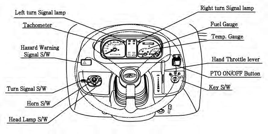
► ► INSTRUMENT AND SWITCHES
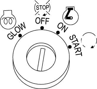
► MAIN SWITCH (KEY SWITCH)
[OFF] -The key can be inserted or removed
[ON] -The electric circuit is on.
[GLOW] - Glow plugs preheat the combustion chamber
[START] -The starter motor is engaged.
When the key is released it will return to the ON position
► HEAD LAMP, TURN SIGNAL SWITCH AND HORN
■ HEAD LAMP SWITCH
High and low beam are operated On the main switch
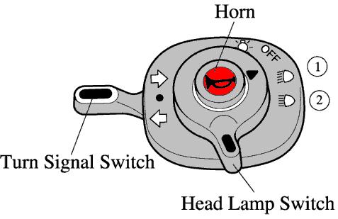
Position ①. Low beam
Position ②. High beam
■ TURN SIGNAL SWITCH
Pull the turn signal lever down to signal a left turn. Push the turn signal lever up to signal a right turn.
■ HORN
Push the Red button.
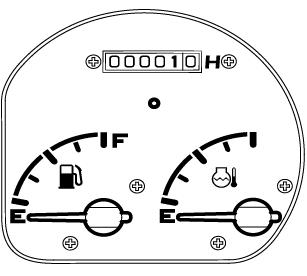
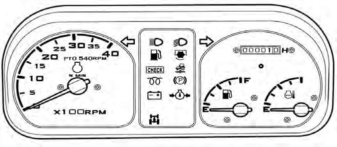
► HOUR METER
The hour meter consists of digits with the last digit indicating 1/10th of an hour.
Symbol Illuminates when Hour meter is operated.
► TACHOMETER
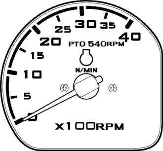
This meter shows the revolutions of the engine and the PTO shafts as well as the travel speed in top gear
► FUEL GAUGE
Shows the amount of fuel in the tank when the ignition switch is ON.
► WATER TEMPERATURE GAUGE
Shows the water temperature with the ignition switch ON
C is low to normal temperature
H is high temperature
If the pointer is in the red H segment the engine is overheating.
Refer this book to rectify the problem.
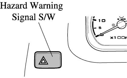
► HAZARD WARNING SIGNAL SWITCH
Push the hazard warning signal once to operate the hazard warning light. (Left and right turn indicators flash). Push the hazard warning light switch again to switch off the hazard warning lights.
Charge lamp
This light will go off as soon as the engine starts to run to indicate that the alternator is changing. (Please note, as broken fan belt can cause the light to come on, please stop the engine as overheating can occur if not rectified immediately)
Oil pressure lamp
Will go out as soon as the engine starts if the oil pressure is correct. If it comes on while the engine is running, stop the engine and get expert advice.
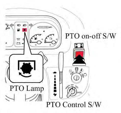
PTO monitor Lamp
Shows the revolution of PTO Refer to monitor lamp on Page 38
High beam lamp is operated on the combination switch.
Low beam lamp is operated on the combination switch
Glow signal Lamp indicates preheating
■ THE PTO MONITOR LAMP on the dash panel indicates the state of the PTO shaft.
1.If the monitor glows: The PTO is rotating
2.If the monitor is off: The PTO is off
1. PTO ON/OFF SWITCH: PTO ON/OFF switch is located on the RHS. on the steering column and can be identified easily with its built in red colored indicator. When the switch is pushed down to start the PTO indicator glows to indicate that the switch and the PTO are in ON position, If the switch is pushed down again the indicator goes off signaling that the PTO is OFF.
Warning
1. If working on hard soils,pavements with a rotary implement the PTO ON/OFF switch must be put to the OFF position to stop the PTO from rotating , If this is not done the rotating blades of the implement will push on the hard ground below and in turn push the tractor toward causing accident which canlead to serious injuries or death.
2. Extra precaution must be taken to clear the area of bystanders/onlookers when using PTO driven implements. The rotating blades of the implements can cause serious injuries on contact.
3.In no case the specified rotating speeds indicated by the implement manufacturer be crossed as the same can lead to serious damage to the tractor/equipment and can lead to serious injuries to persons around.
► ►► ► THROTTLE LEVER (HAND THROTTLE)
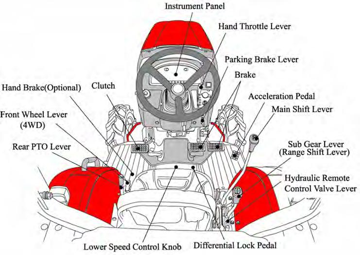
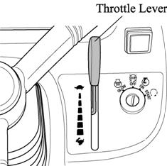
The hand operated throttle lever is located on the RHS of the Dash cover.
To increase the engine speed, Pull the lever downward.
To decrease the engine speed, Push the lever upward. The Lever can be left in any position between idle and maximum as required.
►
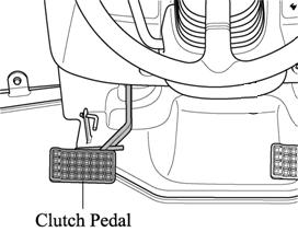
► ► ► SPEED CONTROL PEDAL
The Speed Control Pedal is located in RHS of the Operator floor. Depress the forward speed control pedal to move forward. Depress the reverse speed control pedal to move backward. The speed control pedal will return in neutral position and the tractor will stop when the speed control pedal is released.
and Reverse Lever
► ► CLUTCH CUT-OFF ARM warning
For long term storage of the Tractor it is possible to latch the clutch in the disengaged position. Push the clutch down and engage the latch to hold it there.
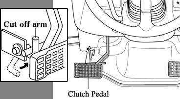
Do not attempt to start engine when this arm is being used.
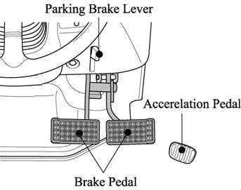
► ► BRAKE PEDAL
Right and left brake pedals are provided to assist in turning the tractor in the field.
A connecting latch is provided to connect the right and left brake pedals for high speed or road use.
Caution
In the interest of safety always use it on the road or at high speed as using one side only can cause rollovers. When servicing the tractor ensure that the adjustment on both sides in the same.
► ACCELERATION PEDAL
This pedal can override a fixed hand throttle setting
► ► PARKING BRAKE LEVER
Connect the brake pedals , push them down while pulling the park brake up to engage. Press the parking brake pedal and push the Brake pedal to release.
Traveling with the parking brake on will damage the brakes. important
►
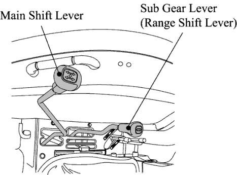
►MAIN SHIFT & REVERSE LEVER(SHUTTLE)
The Main Shift & Reverse Lever is located on the RHS of the operator. The Main shift & Reverse Lever provides three forward speeds: 1, 2, and 3, N (neutral), and one reverse speed, R. Forward speeds may be changed while tractor is in motion if clutch pedal is depressed. Stop tractor and depress clutch before changing direction.
Avoid damage! To prevent transmission damage: important
1.Depress clutch pedal and stop machine motion completely beforeshifting the main shift & reverselever (changing direction forward and reverse ).
2.While operating machine, always depress clutch pedal and stop machine motion before changing travel gears.
3.Never rest a foot on the clutch pedal while machine is in motion.
Operate the main shift & reverse lever only while seated on the tractor. Always stop the tractor before getting off.
The gear shift lever must be in NEUTRAL for the engine to start. Caution
► SUB GEAR LEVER (RANGE SHIFT LEVER)
►
Range shift lever provides three speed ranges: L, M, and H, and N (neutral). Tractor should be stopped and clutch depressed before changing speed ranges.
Choose L, M, or H speed range on range shift lever to match work application.
Main Shift & Reverse leverSub gear lever (Range Shift lever) important
Avoid damage!
Select the proper speed range and gear for the job.
•The machine maybe operated in any gear with engine speeds at 950-2600 rpm. Within these limits, the engine can be placed under varying load operations.
•Never overload engine by lugging machine at low idle speeds.
•Raise engine speed the match expected loads. If a slight increase engine rpm occurs simultaneously with moving hand throttle lever forward, the engine is not overloaded.
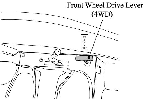
► ►► ► FRONT WHEEL DRIVE LEVER (4WD) important important
The Differential Lock Pedal is located below the LHS of the Operator.
In the ON position the front wheels are engaged and in the OFF position they are disengaged.
Engage & disengage the front wheel drive with the front wheels in the straight position and at low Engine RPM.
Do not use front wheel drive at high speed or on the road as premature wear of components will result.
Always use the clutch when using the front wheel drive lever.
Use of front wheel drive improves traction performance.
►
► ► ► DRIVER’S SEAT
To adjust the seat backwards and forwards lift the lever at the front of the seat and set it to the desired position(Please refer to page 10 of how to adjust the seat)
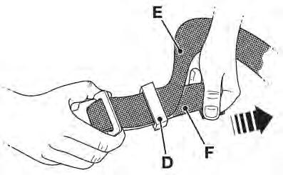
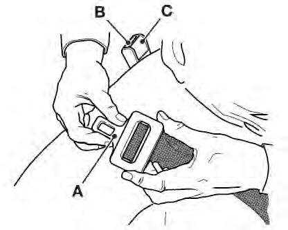
■ ■ Seat Belt
-Release the Seat Belt
Press button C and Pull the Male Fitting A from the Buckle B
-Adjusting the Seat Belt
Make Sure the belt is across your hip and not over your stomach. To adjust the male fitting A : a. To make the strap longer, pull end E as far as it will go. b. To make the strap shorter, pull end F as far as it will go.
1. Pull toggle D down the strap by the required distance.
Pto Selection Lever
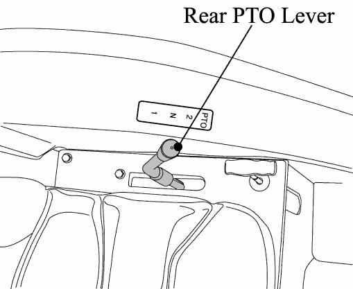
Your tractor is equipped with 1 Speed PTO to suit range of applications and conditions.
Model Positionon
4010gear REAR PTO 540 rpm
Always OFF the PTO On/Off switch when engaging or disengaging the PTO lever.
Do not operate any implement at a high speed than is specified for it. When making adjustments to the implement stop the engine to avoid serious injury. When leaving the tractor stop the engine, and remove the key. Set the parking brake.
►
► OPERATING THE HYDRAULICS
The hydraulics are powered with an engine driven hydraulic pump and controlled with a position control lever mounted beside the driver.
► ► HYDRAULIC POSITION CONTROL LEVER
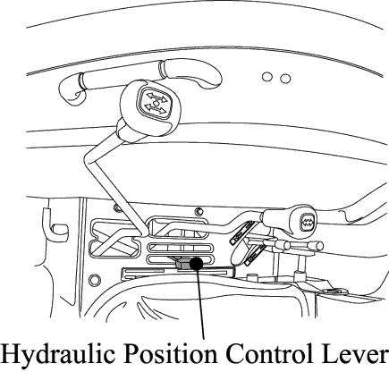
Hydraulic Position Control Lever is located on the RHS of operator Implements can be raised and lowered with the hydraulic position control lever and can be stopped at any position by stopping the lever.
To ensure a consistent working depth the adjustable stop (A) can be set to ensure that the implement returns to the same depth every time.
To raise the implement : Pull the lever backward. To lower the implement : Push the lever forward.
After finishing the work, always lower the implement to the ground and switch off the engine, Set the parking brake to avoid injuries and accidents .
► ► LOWERING SPEED CONTROL KNOB FOR THE 3 POINT HITCH
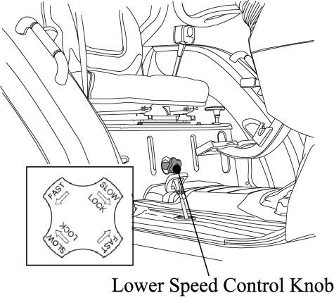
This knob controls the downward speed of the hydraulics three point linkage and is located below the Seat.
To slow the downward speed-Turn the knob clockwise. To increase the downward speed, turn the knob anticlockwise.
To lock the knob clockwise. Do not over tighten the knob.
Caution
Always set the knob to lock when
1.Traveling on the road
2.Replacing tires or blades on an implement.
3.Making adjustments to an implement. Sudden dropping of an implement due to hydraulic problems can cause serious injury or death.
► ► HYDRAULIC REMOTE CONTROL VALVE LEVER –(IF EQUIPED)
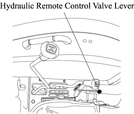
The Hydraulic Remote Control Valve Lever is located on the RHS of Operator. Move the lever up or down and hold.This will raise or lower the implement (Rotavator or Hydraulic plow).
Important:
-Do not hold the lever in the “pull”or “Push”position once the remote cylinder has reached the end of the stroke as this will cause oil to flow through the relief valve. Forcing oil through the relief valve for extended periods will overheat the oil.
-When Using the tractor hydraulic system to power front loader, do not operate the boom and bucket cylinders simultaneously.
► ►► ► HYDRAULIC REMOTE CONTROL VALVE COUPLER CONNECTING & DISCONNECTING –(IF EQUIPED)
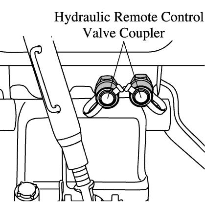
■ Connecting
1.Clean both couplers.
2.Remove dust plugs.
3.Insert the implement coupler to the tractor hydraulic coupler
4.Pull the implement coupler slightly to make sure couplers are firmly connected.
■ Disconnecting
1.Lower the implement first to the ground to release hydraulic pressure in the hoses.
2.Clean the couplers
3.Relieve pressure by moving hydraulic control levers with engine shut off.Pull the hose straight from the hydraulic coupler to release it
4.Clean oil and dust from the coupler,then replace the dust plugs.
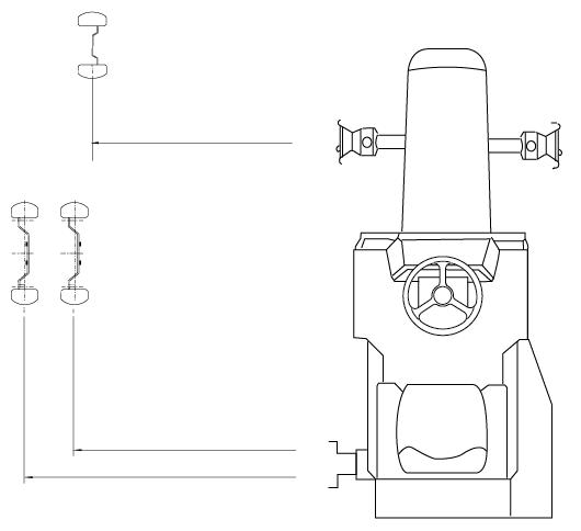
► ►► ► ADJUSTMENT OF THE CHECK CHAIN
To adjust the check chain turn the turnbuckle to lengthen or shorten the chain and tighten the lock nut when the correct adjustment is achieved.
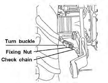
Turn buckle
Fixing Nut
Check chain
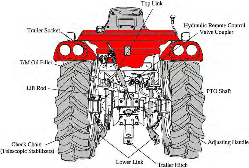
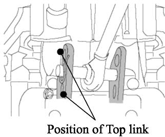
► ►► ► ADJUSTMENT OF THE TOP LINK
Lengthening or shortening the top link will change the angle of the implement.The locating hole of the top link varies with the type of implement used.The most common locations are the 2nd and 3rd hole from the top.
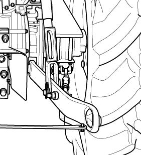
► ►► ADJUSTMENT OF THE LIFT ROD
Adjust the length of the lift rod by screwing the Adjusting Handle (Turnbuckle) in or out. Adjust the length of the lift rod as necessary to set the implement in its working position parallel to the ground.
Lift Rod
Adjusting Handle
Lower Link
► ►► ► ADJUSTMENT OF THE YOKE ROD ON THE LOWER LINK
For different applications change the position of the Yoke rod on the lower link holes as shown and insert the pin in the direction of the arrow.
►
Only use drawbar to tow and keep the 3 point linkage in raised position when toeing with the drawbar. Position can create unbalance causing the Tractor to roll-over & Result the death or serious injury. Danger
Mounting Implement
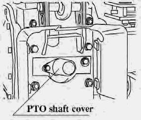
If the PTO is used, remove the safety cover off the PTO shaft. Adjust the yoke rod on the lower links to suit the implement in use.Attach the left lower link, then attach the right lower link using the adjusting handle on the leveling box if required. Attach the top link. Attach the PTO shaft to the tractor if used, making sure that it is locked in place. Adjust the check chains to suit the implement and tighten the locknuts.To remove an implement reverses the procedure
Do not attach a PTO shaft with the engine running and ensure allsafety shields are in place.
Driving The Tractor
► ► STARTING THE ENGINE
Before starting the engine carry out the pre-operational checks as set out on page 27.
(1)Sit on the driver seat
(2)Apply the footbrake.
(3)Put the hydraulic lever in the down position.
(4) Push down the clutch to activate the safety-starting switch.
(5)Put the main gear lever in neutral
(6) Insert the ignition key and turn it on
(7)Ensure that the warning lights are working
(8) Always turn the ignition key to left for a moment & release it. The automatic heater will start working as will be indicatedby a light on the instrument panel .As the lamp goes off turn the key to the start position to start the engine
(9) Ensure that all the warning lights are off with the engine running.
► ►
Important
Never turn the key to the start position while the engine is running as this can cause serious damage to the starter and engine flywheel. Only engage the starter for a period of not more than 10 seconds. If Engine does not start, rest the starter for about 20 seconds and try again for a maximum of 10 seconds.If the engine does not start after repeated attempts, refer to the fault tracing guide.
Important
Especially in cold weather, always allow the tractor to idle fora while to warm up & build up sufficient oil pressure to ensure normal operatingtemperature for longer engine life.
Stopping The Engine
-After light work let the engine idle for a while and turn the key off.
Important
After long or heavy work allow the engine to idle for 5-10 minutes and turn the key off.
►
► ► ► WARMING UP
When starting the engine allow it to warm up to operating temperature by allowing it to idle 5-10 minutes to ensure full lubrication and operating temperature. Failure to do so can shorten engine life substantially.
► ► WARMING UP IN COLD WEATHER
Cold weather will change the viscosity of the oil, resulting in a reduced oil pumping capacity, which can cause damage to the engine if it is not warmed up correctly.It also causes problems with the hydraulic system and the synchromesh in the transmission.
Correct times for warming up are:
Temperature Time for warming up
Above 50°F 5~10 min.
50°F~32°F 10~20 min.
32°F~14°F 20~30 min.
14°F~-4°F 30~40 min.
Below –4°F Over 40 min.
Ensure the handbrake (Foot brake) is on during the warming period. Failure to warm up correctly can result in problems.
Important
When the engine is warm push down the clutch and engage the mainand auxiliary gear levers to the required position. Push down on the brake pedals and release the handbrake. Increase the engine revolutions and let out the clutch smoothly.
Only change gears with main gear lever while moving and ensure that this is done with fully use of the clutch.
► ►
Storing Engine In Operable Condition For 3 Months Or More
When the engine is not operated during storage of three months or more, internal engine parts can rust and lose oil film. As a result, the engine can seize when it is started after storage. To prevent such a rust, the engine must be operated periodicallyduring storage.
Caution
Do not ”ride”the clutch to control speed, use a lower gear. Do not travel with your foot on the clutch pedal.
Danger
Always connect the brake pedals when traveling on the road. Never tow anything except with the drawbar. Do not tow loads which are too large for the tractor’s capacity to brake effectively especially in hilly terrain. Take special care when towing large or wide implements. Do not carry passengers. At all times observe local legislation and road rules.
►► TIGHT TURNS IN THE FIELD
►
Disconnect the latch connecting left and right brake pedals to allow the use of individual pedals.
To make a tight turn use both the steering wheel and the brake pedal at the same time.
For a left turns use the left pedal and a right turn the right pedal.
Caution
Perform tight turns only at a slow safe speed. Doing so at a high speed can cause rollovers and very serious injury or death.
►► NORMAL BRAKING AND PARKING
►
Let the engine come back to idle and at the same time push in the clutch and brake simultaneously.
When the tractor has come to a halt, lower any implement to the ground, and put the main gear in neutral. Apply the park brake, stop the engine, and remove the key.
Caution
Always apply the park brake when parking. Failure to do so can cause accidents and damage. As an extra precaution when parking on a slope, chock the rear wheels.
► ► ► ► UPHILL STARTS ON A STEEP SLOPE
With the pedals connected together push down on the brake pedals and push down the clutch.
Set all gear levers to low and the throttle to medium engine speed. Release the clutch and as it engages release the brake pedals. Adjust the throttle to the required speed.
► ► DRIVING DOWNHILL
Use the engine’s ability to brake when traveling downhill. Never rely on the brakes only and never travel downhill with thegears in neutral.
When operating in hilly terrain the risk of the rollover is increased substantially, please drive with extra care.
When towing trailers in hilly terrain ensure that they are equipped with brakes, use a lower gear to get maximum engine braking and do not change gearson a down hill run
► ► ► OPERATION OF THE DIFF LOCK
►
While the diff lock is a very useful feature, care should be taken in its use as misuse can lead to dangerous situations.
The diff lock would only be used in situations where traction islost on one of the rear wheels.
Use low engine revolutions when using the diff lock.
If the diff lock does not release after removing the foot from the pedal use the left and right brake pedals in turn to release it. Do not try to engage or use the diff lock on tight turns as serious damage can result.
► ►► CHECK DURING DRIVING
Constantly monitor the warning lights on the dash and if any comes on stop the tractor to determine the cause.
If the oil pressure light comes on check the oil level first of all. If the oil level is OK ask a qualified dealer to check the reason for the light coming on.
If the alternator warning light comes on check all connections and ensure that the fan belt is not broken.
If all connections and the fan belt are intact consult your dealer to determine the cause of the problem.
► ► FUEL GAUGE.
Toavoid excessive condensation in the fuel tank refill at the endof each day’s work and ensure during the day that it does not drop to a low level where the fuel system will require bleeding to expel air in the system after refilling the tank.
► ►► ► ENGINE COOLING WATER.
If the gauge indicates that the engine is running hot, stop the tractor and check the coolant in the radiator.
Danger
Allow the engine to cool down before opening radiator cap as serious burns may result due to hot steam & boiling water.
Also check to ensure that the fins in the radiator core are not clogged or that the tractor has a broken or stretched fan belt.
Caution
When traveling on public or farm roads connect both brake pedalsand allow for the weight of any mounted implement to ensure that the unit is not unbalanced. Also allow for the width when passing other road users. Where fitted use the hazard lights provided. Strictly follow the local traffic regulations.
When operating near others with an implement attached take particular care to allow for the width of the implement and avoid accidents.
Caution
► ► TRACK ADJUSTMENT
As 4010 models of Mahindra are front wheel assist the front track can be set in 1 position. The rear track can be set in positions as illustrated.
Tread
Tread
(*) Marking is STANDARD
Section-B