2 minute read
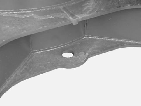
TOWING EYES


WARNING: Towing is always carried out at the risk of the user. The manufacturer’s warranty does not apply to any incidents or accidents which may occur during towing.
WARNING: This operation must be carried out very slowly, over a short distance and only if it is unavoidable.
CD00E069 The towing eyes, located at the front and the rear of the undercarriage, are intended for moving heavy objects up to 9000 kgs (20 000 lbs) maximum. Make sure that the shackles, chains and slings are in perfect condition and strong enough to move the load. IMPORTANT: The load should always be kept in line with the undercarriage.
HOSE BURST CHECK VALVES (OPTIONAL)
Service specifications
Check by your authorized LBX Link-Belt distributor.......................Every 6 months The role of the hose burst check valve is to stop the attachment from dropping due to valve spool leakage in the neutral position or in the event of a line or hose accidentally breaking. In the latter event, they also ensure that the attachment may be lowered gently to the ground. See “Load handling” in the “Operating Instructions” Section.
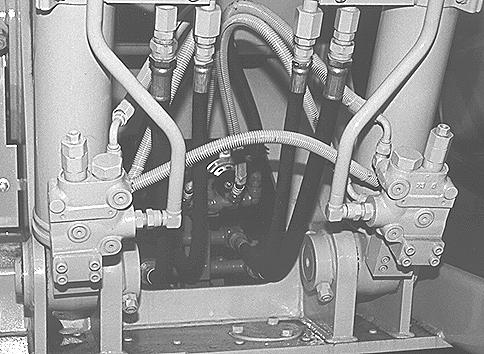
CP98N018
WARNING: Hose burst check valves are pilot operated devices. The operator must return the control lever to the neutral position to prevent the attachment and load from falling in the event that a hydraulic hose or line fails.
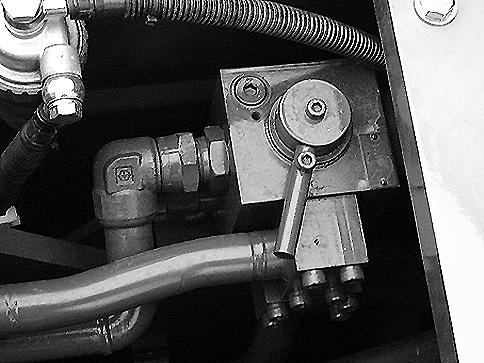
OPTIONAL TOOL FLOW SELECTOR VALVE (OPTIONAL))
This valve is located on the inner wall of the fuel tank and is used to select the correct oil flow for the tool mounted on the machine. See “Auxiliary hydraulic circuits” in the “Operating Instructions” Section. IMPORTANT: Consult your authorized LBX Link-Belt distributor before mounting optional tools.
CD00E043
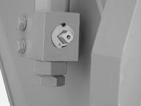
TOOL SUPPLY VALVES (OPTIONAL)
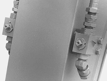
A24690 Located on the end of the arm, these two valves are used to ensure oil supply to optional tools, for example, hydraulic breakers, etc... These valves have two positions.
CD00E055
Position “O” (open) : In this position, oil is supplied to the tool. The valves can be locked in open position “O”. STEP 1
CD00E056
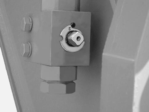
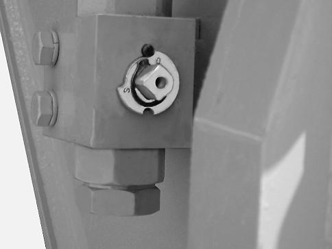
Position “S” (closed) : In this position, there is no supply of oil to the tool.
CD00E055 Using a hexagonal wrench, place the supply valves in “O” position (open).
STEP 2
Remove the snap ring. STEP 3
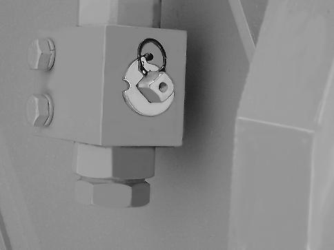
CD00E057
CD00E058 Remove the locking plate and then reinstall it, turning it a quarter of a turn so that the notch is over the locking pin. Install the snap ring.