16 minute read
PERIODIC MAINTENANCE SCHEDULE


All
All
Grease fittings
Engine oil level
Engine oil & filter
Transmission oil level
Transmission oil & filter
Front axle oil level
Front axle oil
Air screens & radiator
Radiator coolant level
Radiator coolant
Items marked (*) indicate initial service interval only. Subsequent (later) intervals marked “ ● ”. Intervals above are for normal usage. Severe operating conditions (wet, dusty, etc.), or when previous servicing has indicated need for more frequent action, intervals may need to be more often.
LUBRICATION/FILL POINTS
FIG. 5-1: General layout of lubrication, fill and drain locations on Tractor:
Note: The indication label is attached to each greasing point.
TABLE 9
Ref. Description Type
9. Oil filter -
10. Suction filter -
11.
12.
13.
14.
15.
16.
Grease fittings (Grease nipple)
Fill points
Drain points
Oil check window
Fill point (coolant)
Drain point (coolant)
Service Access
CAUTION: Shut off the engine before servicing Tractor. Engine hood must be installed and secure prior to operating unit.
To access radiator, battery and engine components, engine hood can be opened.
Opening / Closing Engine Hood
FIG. 5-2 & 5-3 & 5-4: To open the hood, use the tool (1) which is attached to the engine key. There is a hole at the left side of meter panel. Enter the tool to this hole and push it in.
Open the hood.
Use the rod (2) to hold the hood. After maintenance, put the rod back into the storage position, and push down the hood.
Lubrication Details
Grease Fittings
Lubricate all grease fittings (refer to Fig. 5-1) every 50 h of operation using multipurpose lithium base grease. Clean grease gun and fittings before and after greasing to prevent contamination from dirt.
NOTE: The indication label is attached to each greasing point.
NOTE: When operating in muddy or extremely wet conditions, daily lubrication of fittings is recommended.
Engine Oil Filter
CAUTION: Muffler tail pipe is extremely hot just after operation, therefore becareful not to touch it to avoid burns. Be sure to wear gloves before checking engine oil level.
CAUTION: Do not open the filler opening except when checking or replacing the engine oil. Make sure to allow the engine to cool sufficiently before opening the filler opening.
Engine oil and filter should be changed after first 50h of operation and then every 150h thereafter.
FIG. 5-5: To Check Engine Oil Level - Tractor must be parked on level ground with engine off. Pull out dipstick (1) and check that oil level is between upper limit “F” and lower limit “L” on dipstick. Wipe off dipstick, momentarily reinstall in engine and check oil level again.
Add oil through filler opening (2) as required.
NOTE: Add oil slowly to assist in venting air from crankcase.
FIG. 5-6: To Change Engine Oil - Operate Tractor until oil is adequately warmed. Remove drain plug (1) from engine and allow all oil to drain. Reinstall drain plug and fill engine crankcase to upper limit on dipstick.
To Replace Engine Oil Filter - Unscrew element (2) from engine and discard. Make sure original filter gasket has been removed. Lubricate new gasket on replacement element with clean engine oil. Screw on new element until gasket contacts adapter and then tighten element 1/2 turn more.
Clean spilled oil and refill crankcase. Start engine, check for leaks and replenish oil level as required.
Transmission Oil & Filters
CAUTION: Do not open the filler plug except when checking or replacing the oil. Make sure to allow the engine to cool transmission to cool sufficiently before opening the filler plug.
Transmission oil lubricates transmission, center housing, and rear axles and also serves as hydraulic fluid.
Transmission oil and filter should be changed after first 50 h of operation and then every 300h thereafter.
FIG. 5-7: To Check Transmission Oil Level - Park Tractor on level ground. Oil level should be indicated in oil level window (1).
Oil level is replenished, as necessary, by removing filler plug (2) and adding oil through filler opening.
NOTE: Adding oil to transmission will also maintain correct oil level in center housing and rear axles.
FIG. 5-8: To Replace Transmission Oil - Remove drain plug (3) and completely drain oil from system.
IMPORTANT: Completely lower 3-point hitch prior to draining transmission oil.
Always replace hydraulic oil filter while oil is removed. Carefully unscrew oil filter (4) from its adapter, Use of a filter wrench may be necessary.
Clean filter adapter and lubricate gasket on replacement filter with clean hydraulic oil. Install new filter until gasket contacts adapter and tighten additional 2/3 turn, by hand. Do not use filter wrench to install filter.
To clean transmission suction filter (5) drain oil and remove left rear wheel. Unscrew filter and clean filter screen in solvent or kerosene, dry thoroughly and reinstall. Make sure “O” rings (6) are not damaged.
Apply sealant to threads on drain plug(s) and reinstall. Refill system with clean oil to level as detailed.
Start Tractor and allow to idle several minutes while operating hydraulic controls, Shot engine off, lower the 3-point hitch and recheck oil level. Replenish transmission oil as necessary. Check for leaks and correct as necessary.
Front Axle Oil
The front drive axle has a common oil level for the front differential housing and each wheel reduction unit. The oil level should be checked every 50h of tractor operation. The oil should be changed after first 50h of operation and every 300h of operation thereafter.
Check Oil Level
FIG. 5-9: Park the tractor on level ground and shut off the engine. Remove oil filler (1) on the top of the lefthand front axle. Remove plug (3) on the top of final cause on both side to let the air inside the front axle go out. Check that the oil level is half of front axle housing. When the oil level is lower, add oil until half level of front axle.
NOTE: When the oil level is hard to be checked, insert a ruler to see the height to the oil level.
Change Oil
Place a tray under the drain plug (2) Remove the drain plug and let all oil drain out from both wheel reduction units. Wrap the threads of the drain plug with sealing tape and screw it back in securely. Remove plug (3) on the top of final case on both side to let the air inside the front axle go out. Pour fresh gear oil through the oil filler (1).
Cooling System
CAUTION: DO not open the radiator cap except when checking or replacing the coolant. Make sure to allow the engine to cool sufficiently before opening the cap. If the cap is opened while the engine is hot, coolant may be discharged, resulting in a burn or other injury.
Rotate cap slowly to release pressure. Then cap can be safely removed.
FIG. 5-10: Cooling system is filled at factory with antifreeze solution to protect engine and radiator to -34°C. Coolant level should be maintained to 12mm below the filler neck opening (1). Check coolant protection from freezing annually.
NOTE: After adding coolant, start engine and operate until thoroughly warmed so coolant is mixed. Periodically check level of coolant in overflow reservoir to make sure level is located between marks when engine is cold.
Periodically check condition of hoses, belt and clamps and tighten of replace as necessary.
Keep radiator, radiator screen and hood screens clean to permit maximum cooling.
IMPORTANT: Use care when cleaning radiator to prevent cooing fin damage.
When draining the coolant which is inside the engine, loosen the bolt (2) and drain the coolant.
Radiator coolant drain point
When draining the coolant from radiator, loosen the clamp of radiator hose and pick up the drain hose (3). Open the filler neck opening (1) to help the coolant to drain. Then drain the coolant from radiator.
Return the drain hose (3) and pour coolant into the reserve tank up to the “full level” to fill the radiator.
FIG. 5-12: Correct fan belt tension helps to insure adequate coolant flow through cylinder block and radiator. Belt is correctly tensioned when belt deflection is approximately 13mm when thumb pressure is exerted at center of belt span.
FIG. 5-13: To adjust belt tension, loosen alternator pivot bolt (1) and tensioning bracket bolt (2). Pull outward on top of alternator to correctly tension belt and tighten bolt (2) first and then tighten pivot bolt (1).
IMPORTANT: Do not pry against alternator housing or pulley. Carefully pry against alternator mounting flange to prevent damage.
Engine Air Cleaner
IMPORTANT: Never operate engine with air filters removed.
FIG. 5-14 & 5-15: Lift up the engine hood to access air cleaner (1). Air cleaner consists of an outer dry paper element to filter dust particles from intake air. Dust ejector (2) traps dust accumulation that falls from outer element.
Periodically “pinch” dust ejector to release accumulated particles. If accumulation is damp, wipe ejector clean with a cloth.
NOTE: Regular cleaning of dust ejector can reduce filter element maintenance.
FIG. 5-16: Outer element may be cleaned (if in serviceable condition) using following procedures:
1. In case that the element is contaminated with dry dust and dirt, blow off by air-blowing from the inside of the element.
NOTE: Air pressure must be lower than 30psi (200kPa), and make space between the air nozzle and element. Be careful not to damage the elements pleats with air flow.
2. In case that the element is contaminated with carbon and oil, replace the element.
NOTE: Clean the air cleaner frequently. Clogging of air cleaner causes worsening of the engine combustion.
When cleaning the air cleaner, be careful not to damage the air flow sensor. Do not blow high pressure air or spray for cleaning the sensing parts of air flow sensor.
Fuel System
Use only clean diesel fuel of correct grade. Introduction of water or dirt into fuel tank or other portion of fuel system can cause repeated plugging of fuel filter and possible injection pump and injector damage.
IMPORTANT: Do not tamper with injection pump or injector adjustments as doing so may render engine and / or Tractor warranty void and may cause severe engine damage. Consult your ISEKI Dealer.
Fuel Filter
FIG. 5-17: Fuel filter assembly (1) is located at left side of frame LH and is used to strain impurities from fuel before fuel reaches injection pump. Fuel filter incorporates valve (2) to aid in filter servicing and airbleeding of fuel system.
Check filter bowl for accumulation of sediment or water and clean as required.
FIG. 5-18: To replace fuel filter element or clean sediment bowl, turn fuel valve to OFF position (handle to rear).
Carefully loosen spanner nut (1) and remove nut, sediment bowl (2) and “O” -ring (3). Sediment bowl can be cleaned at this time.
NOTE: Do not lose spring (4) between bowl and filter element.
Pull downward on filter element (5) and discard. Examine small “O”-ring (6) in filter head and replace as necessary. Install new element, pushing upward until seated.
Install sediment bowl with spring, “O”-ring, and nut. Tighten nut and wipe up spilled fuel. Proceed to “Airbleeding Fuel System” on following page.
Air-Bleeding Fuel System
If any of the following conditions have occurred, the system should be bled:
・Fuel tank has been permitted to run dry.
・Fuel lines, filter element(s) and other components within system have been disconnected or removed.
・Engine has not been operated for a considerable period of time.
・Engine fails to start, or starts but stops again after a few minutes of operation.
FIGS. 5-19 & 5-20: Fuel system components:
Description Location
(1) Fuel tank seat,under
(2) Filter valve on filter
To bleed air from the fuel system:
・Fill fuel tank (1) until full.
・Turn fuel filter valve (2) to “OPEN” (or ON) position.
・Loosen filter air-bleeding screw (3) and let air bubbles out.
・Loosen air bleeding screw (4) for fuel injection pump and let air bubbles out of the pump
NOTE: Normally, further air-bleeding is not required due to electric fuel pump operating when main switch in, instrument panel is ON. If engine will not start after several attempts, check fuel pump fuses (see “Electrical System”).
Fuel Tank Filler Cap
When fuel tank filler cap is removed, a hissing or popping noise may be noticed. This is due to cap design and is a normal condition. Do not alter cap or use unapproved replacement as fuel leakage may occur in event of Tractor upset.
Throttle Lever
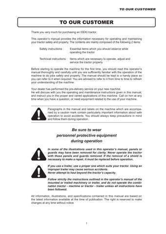
FIG. 5-21: Hand throttle lever should remain in position selected by operator. Through normal use, friction against lever may decrease, causing lever to move out of selected position. Turn adjusting nut (1) as required to retain throttle lever in position selected.
NOTE: Throttle lever friction adjustment is reached by removing the steering column cover, and instrument panel.
Electrical System
Battery
FIG. 5-22: Battery (1) is located under engine hood in front of instrument panel. When battery removal, electrolyte inspection or cable cleaning is necessary, open the engine hood.
Keep top of battery clean and ensure cable connections are clean and tight. Debris on battery can cause discharge of battery and possible source of fire.
DANGER: Batteries produce explosive hydrogen gas when charged. Keep all sparks and open flame away from battery.
When necessary to disconnect battery cables, always disconnect the grounded (-) cable first to prevent short circuits.
Batteries contain sulfuric acid electrolyte (fluid). Wear eye and face protection. If electrolyte comes in contact with skin or clothes, wash immediately. Contact a doctor if electrolyte is ingested or gets in eyes.
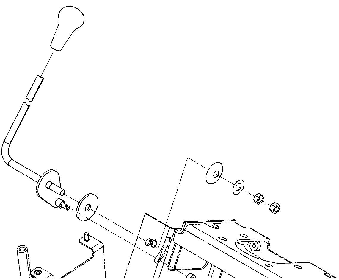
FIG. 5-23: Tractors are shipped with the battery installed. If battery replacement should become necessary, disconnect negative (-) cable (1) first and then remove positive (+) cable (2). Loosen and remove battery securing clamp and carefully remove battery from tractor.
When installing battery, cable (2) connected to starter solenoid should be connected to positive (+) battery terminal first then cable (1) grounded to tractor frame can be connected to negative (-) battery terminal.
IMPORTANT: Do not reverse battery cable connections as severe electrical system damage will result.
NOTE: Make sure replacement battery is of identical size and equal capacity.
Never close or cover vent of battery.
FIG. 5-24: The battery is required the electrolyte inspection.
Make sure that the electrolyte level is between upper limit (A) and lower limit (B). When the level is below lower limit, raise the level with distilled water.
WARNING:
NEVER disassemble battery. Batteries contains sulfuric acid electrolyte (fluid). Keep away from sparks or flames, which could cause explosion.
When charging battery from an external source, Set charging voltage below 16V. Set charging ampere below 1/10 of the battery capacity. Prevent overcharge. Battery temperature must not exceed 113°F (45°C).
When connecting and disconnecting battery cables, turn off power of battery charger. If you have any questions about the battery, consult your dealer.
If the battery performance become poor, the battery should be removed and recharged from an external source following battery charger instructions. Repeated battery charging may be due to a defect in tractor charging system and/or a defective battery.
IMPORTANT: Do not quick-charge the battery, or it may damage the battery and decrease its performance.
IMPORTANT: Charge the battery before the first use of this tractor.
IMPORTANT: When storing tractor for long period without operation, self discharge of battery will happen (especially in winter). If the tractor is stored for more than 1 month, the battery minus terminal should be disconnected.
When operating for the first time or after long term storage, check if the battery charge level is enough. (If measurement of battery voltage is available, check if the voltage is more than 12.5 V.) When the tractor is stored more than 2 months in summer or 3 months in winter, charge the battery.
Starting Switches
This Tractor is equipped with a neutral-start system consisting of neutral switches and a relay. To start Tractor, ALL the following is required:
Range shift lever must be in neutral position PTO clutch lever must be OFF.
WARNING: DO NOT bypass or modify the neutral switch system. If the neutral start system does not operate properly, consult your Dealer immediately.
Wiring / Fuse Arrangement
CAUTION: Keep all wiring connections clean and tight. Make sure wiring is correctly secured to prevent damage.
CAUTION: DO NOT alter wiring by adding “homemade” extensions or replacements. Doing so can eliminate fuse protection and/ or eliminate safety features of the system.
CAUTION: Tractor is equipped with negative (-) ground system. Tractor metal parts provide many electrical connections. For this reason, all positive (+) circuits must be insulated to prevent “grounding” or short circuits and prevent possible fire.
CAUTION: DO NOT replace any fuse with a fuse of higher amperage rating. DO NOT use wire (or foil) to bypass fuse protection. Fire can result.
If fuses blow repeatedly, examine electrical system for “grounded” or “shorted” circuits.
Fuse / Head Light
FIG. 5-25: Main Fuse Box, A-Located on right side, to rear of engine.
TABLE 10
FIG. 5-26: Slow-Blow Fuses, - In-line fuses protect relevant circuit by melting when sustained heavy electrical load or short circuit is encountered. Feature a delayed action to prevent current disruption when brief surges are encountered.
(40A) slow-blow fuse, for main circuit is green in color. Fuse is located on right side of battery.
Function of slow blow fuse
TABLE 11
Ref. Amp Function
1 40A Alternator Circuit
2 40A Starter Circuit
IMPORTANT: Fuses are of specific amperage capacity for the circuit in which they are located. Do not replace fuses with unauthorized parts.
7 Pin Socket
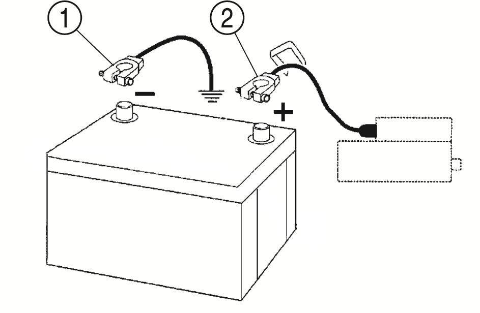
FIG. 5-27: 7 pin socket is located at the rear of the tractor.
TABLE 12
Ref. DIN Function
1 L Left-hand rear direction indicator
2 54G Not used
3 31 Earth (-)
4 R Right-hand rear direction indicator
5 58R Right-hand rear light
6 54 Right and left-hand brake stop lights
7 58L Left-hand rear light & number plate light
NOTE: The letters and numbers in the reference column are marked on the rear of the socket and plug, next to each terminal.
Lamps
(a) Head lamps 12V 60W
(b) Front turn signal lamps 12V 21W
(c) Front small lamps 12V 5W
(d) Stop lamps 12V 21W
(e) Tail lamps 12V 5W
(f) Rear turn signal lamps 12V 21W
(g) License plate lamp 12V 5W
NOTE: A special fuse is used - use only genuine ISEKI parts.
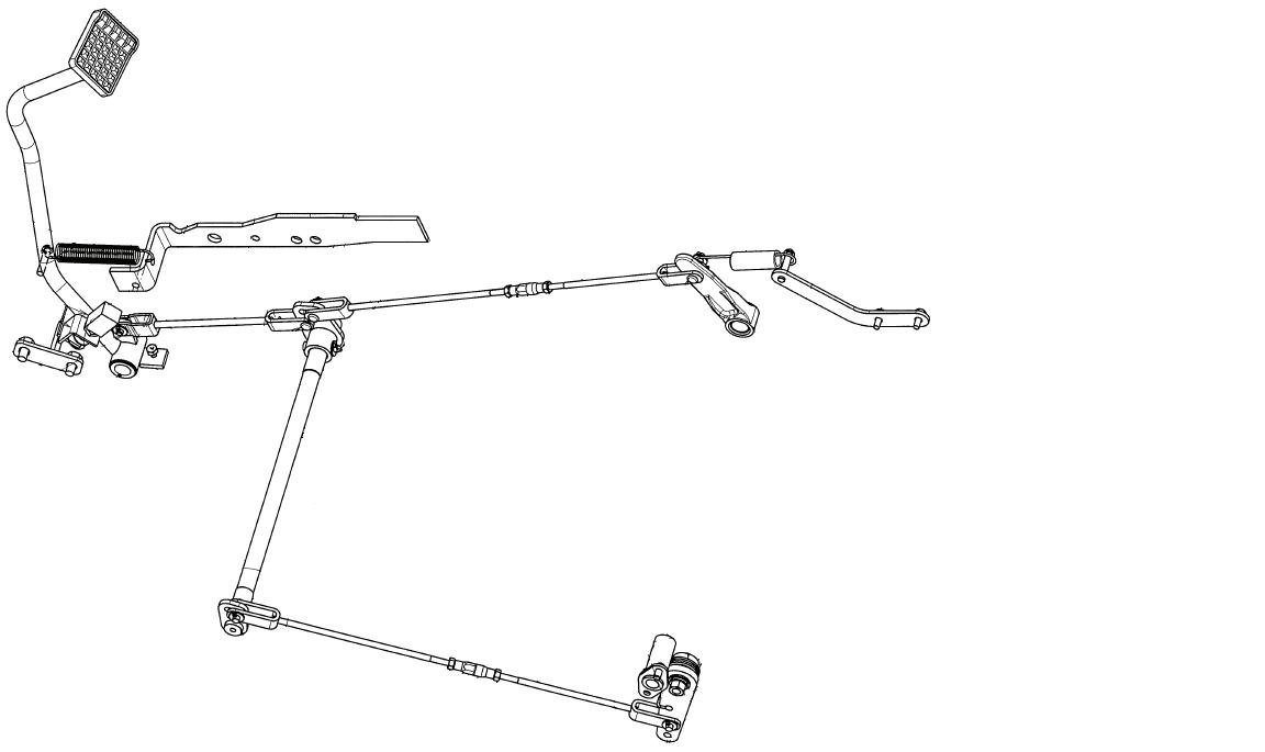
Brake Adjustment
FIG. 5-28: Correct free-play (A) is 30 to 35mm.
NOTE: Through use, free-play will increase and brake balance will be affected. Adjust and balance brakes before free-play is excessive.
FIG. 5-29:
1. Jack up the rear axle, and lift the rear tires from the ground.
2. Depress differential lock pedal by using a wedge to keep the depressed condition(differential lock applied).
3. Release parking brake, and make sure that rear tires rotate.
4. Remove the left side rod pin (1). Let the left side brake be free.
5. Adjust the right side rod by turnbuckle (2) so that the brake pedal play will be from 25mm to 35mm.
6. In this condition, only right side brake rod connected, depress brake pedal, and make sure that rear tires do not rotate.
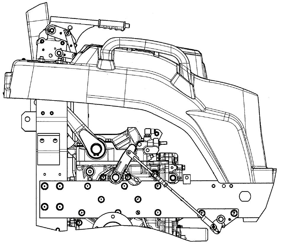
7. Remove right side rod pin (3), and reinstall the left side rod pin (1).
8. Adjust the left side rod by turnbuckle (4) so that the brake pedal play will be from 35mm to 45mm.
9. In this condition, only left side brake rod connected, depress brake pedal, and makes sure that rear tires do not rotate.
10.Reinstall right side rod pin (3). This condition is that right and left side rod pin connected. Depress brake pedal, and make sure that rear tires do not rotate.
Parking Brake Lever Adjustment
FIG. 5-30:
1. After the adjustment of brake pedal, adjust parking brake.
2. Adjust parking brake rod by turnbuckle (1) so that rear right and left tires do not rotate.(parking brake lever position between 3 to 6 notches).
3. Release parking brake lever, and make sure that rear tires rotate.
Hydrostatic Adjustments
For adjustments of the hydrostatic linkage, consult your Iseki dealer.
WHEELS & TYRES
Examine wheels and tyres periodically for correct inflation pressures, tight wheel bolts, and any physical damage that may be a detriment to Tractor operation and operator safety. Correct condition prior to Tractor operation.
Tyre Inflation Pressures
TABLE 13: Maintaining correct tyre pressure will help insure tyre long life. If tyres have deep scratches, cuts or punctures, the respective tyre should be repaired or replaced by qualified personnel as soon as possible.
IMPORTANT: If necessary to replace any tyre(s), ensure original tyre size is used. This is particularly true on 4WD models to ensure correct amount of front axle over speed (or lead) is maintained.
Wheel Bolt Torque
FIG. 5-31: Periodically check all wheel bolt torques. Correct bolt torques:
Front Wheel Bolts (1) 137.2~156.8Nm
Rear Wheel Bolts (2) 87.2~102.9Nm
DANGER: Correct wheel bolt torque must be maintained. Installation of front mounted implements (ex; loaders) impose increased loads and require frequent checking of wheel bolts.
WHEELS & TYRES
FIG. 5-32: Correct “toe-in” dimension of front wheels (A minus B) is 2 to 6mm.
NOTE: Measure toe-in, from tyre center to tyre center at a point halfway up on face of each tyre.
To adjust, remove clip securing rubber boot to tie rod. Loosen lock nut and rotate the tie rod to adjust. Tie rod ball joints should freely rotate in cylinder ends. Adjust each side evenly. Ball joints must move freely after lock nuts are tightened.
Steering Free-Play
FIG. 5-33: Steering should be checked for excessive looseness, as indicated by steering wheel free-play. Maximum free-play is approximately 30mm when measured at outside of steering wheel rim, “X”. Excessive free-play can be caused by:
Loose or worn ball joints.
・Worn or damaged steering column shaft/universal joints.
・Air in steering system.
・Worn or damaged power steering unit.
CAUTION: Excessive steering free play must be corrected before use. Contact your ISEKI Dealer.
Torque Chart
TABLE 14: All fasteners should be tightened in accordance with torque chart unless a specific torque value is called out in relevant maintenance information.
Washing The Machine
Wash the machine periodically. Carefully wash the area where mud spatters easily such as fender inner part.
CAUTION: If you use high pressure washer, be sure to use in accordance with this operator’s manual and safety label of washer. In case of irregular use, it may cause personal injury and damage to the machine.
CAUTION: Set the nozzle of hose ‘spread’ and keep the distance more than 60 cm in order to avoid damage to the machine. Especially, be care for not to hit the water to electrical parts and label.
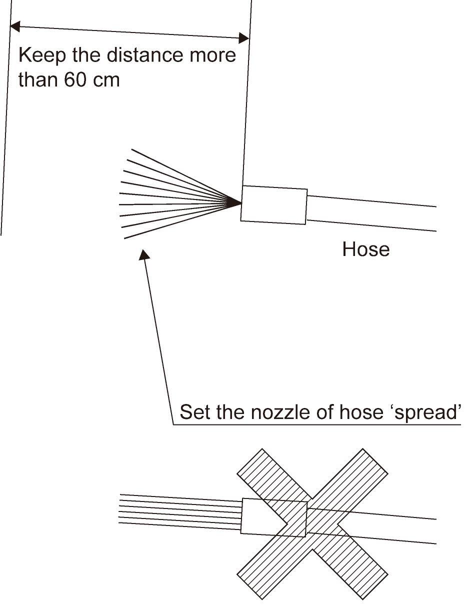
FIG. 5-34: Unsuitable washing may cause the following accidents;
1. Fire as a result of short circuit or the damage to the electrical parts.
2. Oil leakage as a result of the damage to the hydraulic hose.
3. Damage to the machine.
(1) Label is came off.
(2) Accident occurs by the damaged electrical parts, engine, radiator, and interior.
(3) Rubber parts (tire, seal) and resin parts are damaged.
(4) Paint is came off.
Storage
FIG. 5-35: If Tractor is to be stored for extended periods, such as off-season nonuse, certain measures should be taken for its preservation during such periods. These measures will vary according to geographical area and storage season.
1. Replace engine oil and filter. Operate at low idle 5 minutes to lubricate parts.
2. Lubricate all grease fittings and lightly oil control linkage pivots.
3. Detach implements.
4. Store Tractor in enclosed area, if possible, for protection from weather.
5. Block up Tractor to remove weight from tyres and to protect tyres from oily or damp floor.
6. Raise and lock 3-point lift linkage in up position by turning lowering rate control knob (1) fully clockwise.
FIG. 5-36: Step 7 - Fill fuel tank to prevent condensation from forming on inside of tank. Turn filter valve (2) to OFF position.
8. Remove battery and store in cool dry place. Maintain charge during storage period.
9. If Tractor is stored during cold weather season insure that antifreeze is adequate. Alternatively, radiator and engine block may be drained.
10. Check with your diesel fuel supplier on the availability of a diesel fuel additive to place in the fuel system during storage period.
11. If Tractor cannot be placed in an enclosed area, place it under some sort of cover and cover exhaust pipe to prevent entrance of rain or snow.
Major Consumables List
HAZARD