31 minute read
TRACTOR IDENTIFICATION


Statutory Plate
FIGS. 2-1 & 2-2: Statutory plate (1) is located below operator’s seat. The statutory plate contains EU homologation information such as type, variant, EC number, identification number, total permissible mass, and permissible towable mass.
MODEL / SERIAL NUMBER
Each tractor is identified by means of tractor model and serial numbers. As a further identification, engine and chassis are provided with identification numbers.
To ensure prompt, efficient service when ordering parts or requesting repairs from authorized dealer, record these numbers in spaces provided.
FIGS. 2-3 & 2-4: Tractor identification plate (2) is located below operator’s seat. The tractor identification plate contains mode / type names, and production year in addition to tractor serial number.
TRACTOR MODEL / TYPE
TRACTOR SERIAL NUMBER
MFG DATE 05 / 2019
FIG. 2-5: Chassis number (3) is stamped on right side of front frame.
CHASSIS NUMBER
NOTE: Reference to lift-hand and right-hand, used throughout his operator’s manual, refers to the position when seated in operator’s seat and facing forward.
FIG. 2-6: Engine model number (4) is cast on right side of engine block, below the injunction pump.
Engine serial number (5) is stamped on cylinder block, below engine model number.
Major Components
FIG. 2-7: Identification and terminology of major components, as given in this book, are as follows:
Instrument Panel
FIG. 3-2: Gauges, control switches and indicators are located in instrument panel. Items are as follows:
1. Hazard Warning Lamp Switch
2. Coolant Temperature Meter
3. Indicator Light Array
4. Tachometer
5. Engine Hourmeter
6. Fuel Gauge
7. Horn Switch
8. Direction Indicator Lamp Control Lever
10. Beacon lamp switch
Main Switch
FIG. 3-3: Main Switch (1) has the 4 following positions:
OFF....... Engine and all electrical circuits are off. Key can be removed.
ON........ Power is supplied to all circuits. This position is normal operating position.
GLOW... Energizes glow plugs to assist starting by preheating the combustion chambers.
START... Starter activates and engine starts.
NOTE: The main switch must be turned to “ON” before any circuits will operate. The clutch pedal must be depressed before the engine is started.
IMPORTANT: When the main switch is selected to “GLOW” position, the engine combustion chambers will be preheated and allow cold engine to be started after several seconds.
Indicator Light Strip
FIG. 3-4: Indicator light strip contains several warning lights to monitor certain functions. Currently used positions (from left to right) are:
• Glow Lamp - Illuminates when the main switch is turned to the GLOW position. The lamp illuminates until the glow is ready.
• 4WD Indicator Lamp - Illuminates when 4WD is engaged by pulling 4WD drive shift lever.
• Trailer Indicator / Hazard Warning LampIlluminates when the trailer is attached by connecting with the 7 pins socket, or the hazard warning lamp switch is ON position.
• Parking Brake Lamp - Illuminates when parking brake is applied.
• Engine Oil Pressure Warning Lamp - Illuminates if engine oil pressure is low. If the lamp comes on while the engine is running, stop the engine immediately.
• Battery Charge Lamp - Illuminates when the main switch is turned to the ON position and will go out after the engine starts, to indicate the battery is being charged.
• Power Take Off (PTO) Drive Warning LampIlluminates when the PTO clutch lever is moved to On position. It will go out by moving the PTO clutch lever to OFF position.
• Left-hand Side Direction Indicator LampIlluminates when the direction indicator lamp control is turned to the left-hand side direction indicator lamp position (Lower position).
• Right-hand Side Direction Indicator Lamp
- Illuminates when the direction indicator lamp control is turned to the right-hand side direction indicator lamp position (Upper position).
Switches
FIG. 3-5: Horn / Light / Turn Switch.
Horn Switch (1) - is for activating the horn.
Headlamp Switch (2) - is a rotary switch with two operating positions:
• (A) OFF position - All lamps off.
• (B) ON position - Dipped beam headlamps and rear tail lights on.
Direction indicator lamp control lever (3) - Operate lever (3) to the direction that the tractor is going to turn. Then front and rear left-hand or right-hand direction indicator lamp flashes as a turn signal. In order to cancel it, return the lever (3) to center position.
FIG. 3-6: Hazard warning lamp switch (4) - Press the switch to turn on hazard warning lamp. Both lefthand and right-hand direction indicator lamps will lamp at the same time.
Fuel Gauge
FIG. 3-7: The gauge indicates fuel level in the fuel tank when the main switch is in the “ON” position.
NOTE: The gauge cannot indicate an accurate fuel level when the tractor is on an incline. It takes while to indicate an accurate level after the tractor back to its horizontal position.
NOTE: After refilling the fuel, do not forget to close the fuel filler.
Coolant Temperature Gauge
FIG. 3-8: Gauge indicates engine coolant temperature when the main switch is in the “ON” position.
・ C - Shows too cool temperature for severe work. Allow to warm (needle in mid position) before applying heavy load.
・ H - Indicates overheating (red area on gauge). Reduce engine speed to idle, allow to run at no load several minutes and investigate cause (refer to “Troubleshooting”).
CAUTION: Do not service hot engine. Allow to completely cool before servicing or removing radiator cap.
Tachometer & Engine Hourmeter
FIG. 3-9: The Needle (1) indicates engine speed in crank shaft revolutions per minute (rpm). Index is also provided to show rear PTO speed of 540 at approximately 2 484 engine rpm.
Normally, PTO speed should be between 540 and 600. Operating PTO at a speed above 600 is too fast, and may result in a breakdown of the tractor or implement.
Engine Hourmeter (2) in the center of gauge indicates engine and tractor use to help in maintenance intervals. The extreme right digit indicates 1/10 hour increments.
Brakes
Brake Pedal
FIG. 3-10 & 3-11: Brake pedal (1) controls left and right wheel brakes at the same time.
NOTE: L type: Brake pedal is located on the left side.
Except L type: Brake pedal is located on the right side.
Parking Brake
The parking brake acts on the tractor rear wheels. To apply parking brake, pull the parking brake lever (2) upward to lock brakes in applied position.
To disengage parking brake, push release button (3) and lower the lever (2) to the released position.
IMPORTANT: Always disengage brake before driving the tractor to prevent an abnormal brake wear
NOTE: When the parking brake is not applied and engine is turned off, parking brake lamp (4) (at the left hand side of mater panel) will illuminate and let you know to apply the parking brake.
Engine Speed Controls
Throttle Lever
FIG. 3-12: The throttle lever (1) controls engine speed and will stay in the position set by the operator.
• Move throttle lever rearward to decrease the engine speed.
• Move throttle lever forward to increase the engine speed.
CAUTION: Always select engine speed to ensure safe operation. Reduce speed prior to turning or backing Tractor.
Transmission Shift Lever And Controls
FIG. 3-13: The gearshift lever is used to select a range of ground travel speeds through different gear reductions within the drive train. A hydrostatic control unit has unit has infinitely variable speeds, from zero to top speed in each range gear.
Range Gearshift Lever (1) is located to right of operator seat, and supplies two major speed changes. This lever has “tortoise(slow)”, neutral and “hare(fast)” positions.
IMPORTANT: Completely stop all machine movement before you shift the range gear shift lever.
HST Pedal (2) & (3) are Located on right side of the platform. The pedals operates the hydrostatic unit in forward or reverse travel direction, when the range gearshift lever is in the tortoise(slow) or hare (fast) position.
・ Press the forward pedal (2) to move the machine forward.
・ Press the reverse pedal (3) to move the machine rearward.
・ Ground speed will increase as the pedal is pressed.
When the pedal is released, the spring-loaded pedal will return to the neutral position. The machine will slow, then stop when the hydrostatic neutral position is reached. When the pedal is completely released and in the neutral position, the machine will remain stopped.
Differential Lock Pedal
FIG. 3-14: When the differential lock pedal (1) is pressed, the rear axles are locked together so the rear wheels turn together at the same speed. This is especially important when you operate in loose soil or slippery conditions.
Disengage differential lock, by releasing foot pedal.
IMPORTANT: Stop Tractor before engaging differential lock.
CAUTION: When the differential lock pedal is engaged, the steering control of tractor will decrease. Disengage the differential lock before you turn. Do not use during transport.
4-WHEEL DRIVE SHIFT LEVER
FIG. 3-15: Shift lever (1) engages and disengages drive for the front axle. Lever forward, the front axle is engaged, and power is available to both front and rear axle. Lever rearward, the front axle (4WD) is disengaged.
IMPORTANT: Stop Tractor before engaging or disengaging 4 -wheel drive.
Do not use 4WD on hard surface. Rapid wear of front tires and possible drive line damage could occur if 4WD is operated for prolonged periods on hard surface.
Pto Clutch Lever
FIG. 3-16: PTO (Power Take-Off) clutch lever (1) engages and disengages both PTO’s (Rear PTO, Mid PTO, or both at same time) on Tractor.
When lever is forward, PTO (Rear PTO and Mid PTO) is engaged.
When lever is returned to rear disengage position, the gear drive is disengaged.
CAUTION: Always shut off PTO and shut off Tractor engine before servicing PTOdriven implement. Allow all movement and motion to stop before leaving operator’s seat.
REAR & MID PTO SELECTOR LEVERS
FIG. 3-17: Rear PTO (Power Take-Off) selector lever ( 1) controls rear PTO on Tractor.
When lever is forward, neutral position, the gear drive is disengaged.
When lever is rearward, 540 rpm rear PTO is selected.
CAUTION: Always shut off PTO and shut off Tractor engine before servicing PTOdriven implement. Allow all movement and motion to stop before leaving operator’s seat.
Mid PTO (Power Take-Off) selector lever (2) controls mid PTO on Tractor.
When lever is forward, neutral position, the gear drive is disengaged.
When lever is rearward, 2 000 rpm rear PTO is selected.
CAUTION: Always shut off PTO and shut off Tractor engine before servicing PTOdriven implement. Allow all movement and motion to stop before leaving operator’s seat.
CAUTION: Always select engine speed to ensure safe operation. Reduce speed prior to turning or backing Tractor.
3-POINT LINKAGE
Complete operating instructions for 3-point linkage are given in “Operation” section of this book.
Control Lever
FIG. 3-18: 3-point linkage position control lever (1) adjust height of 3 point hitch on rear of Tractor. Setting lever in a particular position will set the height respectively. Full up position is with lever fully rearward and full down position is with lever completely forward.
CAUTION: Use position control lever (1) when attaching or detaching implement.
NOTE: When starting engine, ensure implement is lowered to ground and position lever is fully forward.
This reduces load on starter due to hitch trying to raise when engine is cranked.
Lowering Rate Control Knob
FIG. 3-19: Lowering rate knob (1) adjusts “rate of drop” of 3 point implements. Turning knob clockwise will increase lowering time and counterclockwise will decrease lowering time. Turning knob fully clockwise will lock implement (or hitch) in raised position for transport.
CAUTION: When working near or under mounted equipment, securely block in position and turn lowering rate clockwise to “stop”.
Cutting Height Control Knob
FIG. 3-20: Adjustable in 7 stages by cutting height control knob (1). Turning knob clockwise will raise the cutting height of mower deck and counterclockwise will lower the cutting height of mower deck.
・When changing cutting height, raise the mower deck to the highest position by control lever before turning the cutting height control knob.
・The knob cannot be turned when the mower deck is in the lowest position.
CAUTION: When operating without mid mount mower deck, the linkage for mower deck must be in fully up position by using position control lever. Also, Turn the cutting height control knob to counterclockwise and to set highest position.
Beacon
FIG. 3-21 & 3-22: Beacon switch (1) and wiring are standardly equipped.
Beacon terminal is located at the rear center part of the machine. It is fixed to the harness with tape. Wire color of beacon terminal is black and pink with black line.
Spare Power Supply
FIG. 3-23: Terminal for spare power supply is located at the rear center of the machine, It is fixed to the harness with tape. Wire color of spare power supply terminal is white with red line
SEAT & SUSPENSION ADJUSTMENT
CAUTION: Never make seat adjustment while Tractor is in motion. Make sure adjustment is “locked” prior to operation unit. In case of installing local arrangement, you must connect the seat switch with the harness at tractor side. Otherwise, seat switch does not function as a safety system and this may result in unexpected accidents. To enable the seat switch to function as a safety system correctly, consult your dealer.
FIGS. 3-24 & 3-25:
Seat- Woochang W10, COBO GT62 M200
Driver’s Weight Adjustment, 1 -
The seat’s suspension settings is adjusted for the driver’s weight by turning driver’s weight adjustment control. To increase the tension position, turn the driver’s weight adjustment control clockwise, A. To decrease the tension position, turn the driver’s weight adjustment control counterclockwise, B.
NOTE: Adjust the suspension so that the vibration becomes minimum.
Height Adjustment, 2 -
The seat height is adjusted by turning height adjustment knob. To increase the height position of the seat, turn the height adjustment knob counterclockwise, A. To decrease the height position of the seat, turn the height adjustment knob clockwise, B.
Fore-Aft Adjustment, 3
The seat is slid forward or backward by pulling fore-aft adjustment lever.
BREAK-IN PERIOD
Operation of tractor within the first 50h can be a major factor in determining the performance and life of the engine and Tractor:
OPERATION STARTING Pre-Start Inspection
・The engine may be operated at full rpm but excessive load should be avoided. If engine begins to “lug”,operate in a lower gear to maintain higher engine speed.
・ Check coolant level and check engine, transmission and other oil levels frequently during break-in period.
Watch for evidence of leakage of above fluids. Replenish levels as required and repair any leaks that may have formed.
・Tighten any nuts, bolts, or screws that may have loosened and retighten as necessary. This is especially true of wheel retaining bolts. All fasteners on this Tractor are metric.
・Be observant of clutch and brake pedal free-play adjustments and readjust as required. Lining materials used in clutch disc and brake shoes “bed in” the first few hours of operation and may necessitate the need for early and frequent readjustment.
・ Keep area around fuel tank filler clean. Make sure diesel fuel is of correct grade and free of contamination.
・Initial engine oil and oil filter change is after first 50h of operation. Subsequent change interval is every 150h for engine oil and filter.
CAUTION: Proper maintenance practices cannot be over-emphasized. They are required for safe operation. Consultant “Lubrication and Maintenance” section for full details.
Prior to daily start-up of Tractor, a few basic procedures should be followed to ensure Tractor is in operating order to insure longer life and dependability:
・Make sure all safety shields are in place and secured properly.
・Make sure operator is instructed in correct and safe operation of Tractor and related attachments or implements.
・Check coolant, engine oil and transmission oil levels and replenish as necessary.
・Check fan belt tension and adjust as required.
・Make sure radiator, air intake screen, and radiator screen are clear of debris to provide maximum engine cooling.
・Check operation of clutch, brake and throttle controls. All controls must operate freely and be adjusted correctly.
・Conduct a general inspection of tires, tire pressure, and wheel bolt torque. Observe for external signs of leakage and correct before operating Tractor. Check steering for excessive looseness.
・Check for adequate fuel supply. If is recommended fuel tank be filled following each days use to; reduce condensation and provide full tank for next use.
・Check operation of lights and warning flashers. If Tractor is to be transported on public road, ensure slow moving vehicle emblem is in place.
NOTE: Requirements may vary regarding use of warning flashers and slow moving vehicle emblem depending on locality. Check local safety codes.
WARNING: Carefully read and understand the SAFETY section of this book. Your life, and that of others, can be in danger during the starting of the Tractor.
Always start and operate the engine in a well ventilated area.
If in an enclosed area, vent the exhaust to the outside.
DO NOT modify or tamper with the exhaust system.
Normal Starting
FIGS. 4-1 & 4-2: To start engine, proceed as follows:
1. Apply parking brake (1).
2. Put range gearshift lever (2) in neutral position.
3. Make sure PTO clutch lever (3) is in “off” position.
WARNING: Range gearshift lever must be in neutral position and PTO clutch lever must be in disengaged position.
4. Make sure HST pedals (4) are in neutral position.
5. Put position control lever (5) in down position.
6. Move throttle lever (6) to middle position.
7. Turn main switch to “ON” position (7) for 1-2 seconds
8. Turn main switch to “GLOW” position (8) for 5-10 seconds.
9. Turn main switch to “START” position (9). Release main switch the moment engine starts.
10. When the engine runs smoothly, set the engine speed to approximately 1 500 rpm to let the engine and the hydraulic system warm for several minutes. Do not load a cold engine.
WARNING: Range gearshift lever must be placed in neutral position to actuate neutral switch and permit operation of the starter motor.
FIG. 4-3: Battery charge indicator lamp (1) and engine oil pressure lamp (2) on indicator light strip should go out when the engine starts. If either light remains lit, STOP ENGINE IMMEDIATELY and investigate source of problem.
NOTE: If Engine will not start and run after several attempts, refer to “Maintenance” section in this book and bleed any air that may be present in the fuel system.
Restarting Warm Engine
When restarting an engine that is still warm from previous use, the same procedure is used as with “Normal Starting” except step No.6 may be omitted. Use of glow plugs is not necessary when starting a warm engine.
Cold Weather Starting
Procedure for starting an engine in colder ambient temperatures is identical to “Normal Starting” procedure except for the following:
1. Longer use of glow plugs may be required. Instead of the normal 5-10s, main switch may need to be selected to “glow” for 10-20s to adequately warm engine combustion chambers.
2. At temperatures below 4°C (39°F) use of No.1 (No.1-D) diesel fuel is recommended due to possible “fuel gelling” characteristics of No.2 (No.2-D) fuel at cold ambient temperature.
3. The central hydraulic reservoir in addition to transmission and center housing lubrication, will require additional warm-up time due to colder (thicker) oil. Refer to “Warm-Up Period” at right.
4. Test all controls (steering, braking, etc) prior to operating the tractor.
NOTE: Installation of accessory engine block heater is recommended in cold weather conditions. Consult your ISEKI Dealer.
IMPORTANT: Under no circumstances should either or other starting fluid be used to start engines equipped with glow plugs. Severe engine damage will result should starting fluid contact a hot glow plug.
If, for some reason, a booster battery is required to start Tractor, ensure booster battery is connected in parallel. When using booster battery and booster cables always connect positive (+) terminals together first. Then install booster cable on booster battery negative (-) terminal and ground final booster cable end on Tractor away from Tractor battery.
Warm-Up Period
After starting a cold engine, let engine idle at slow speed to make sure all engine components are lubricated. In colder ambient temperatures, extended warm-up will be required to also warm hydraulic fluid and lubricate drive line components. Suggested warmup period:
IMPORTANT: Improper warm-up can result in:
・Severe engine damage
・Hydraulic pump seizure
・Drive line bearing /gear damage
・Sluggish steering /braking
CAUTION: Make sure parking brake is securely applied and all controls are in neutral while warming unit. Do not leave unit unattended.
Operator Observations
Constant attention should be paid to the following points during operation:
・Engine oil pressure lamp will come on in case of low engine oil pressure. Stop engine immediately.
・Battery charge lamp will come on if battery is not being charged properly. Stop engine and investigate cause.
・ Coolant temperature gauge needle will indicate H(hot) in case of over-heated engine. Stop engine, allow to cool, and investigate cause.
・Fuel level should not be allowed to empty as running out of fuel may result with need to bleed air from fuel system.
CAUTION: DO NOT attempt to service Tractor with engine running or hot. Allow to cool.
NOTE: Refer to “Trouble-Shooting” when defect is indicated, to assist locating problem.
Starting Circuit Operation
Tractor is equipped with a switch system to protect the operator.
To permit Tractor to be started (starter motor to operate), ALL the following is required:
・ Operator seated on the seat.
・Range gearshift lever in Neutral.
・PTO clutch lever in disengage position.
WARNING: Neutral switch system is installed for your protection. DO NOT bypass or modify the neutral start switch system. If the neutral start switch system does not operate properly as detailed above, contact your Dealer immediately and have the system repaired.
Periodically check that the starting circuit is functioning correctly. The procedure for this is check list as follows.
1. Check that there are no bystanders around the tractor should it inadvertently start.
2. Depress the brake pedal. Attempt to start the tractor with the range gear and PTO in neutral position. The Tractor should start.
3. Depress the brake pedal. Attempt to start the Tractor with the range gear engaged and the PTO in ON position. The Tractor should NOT start.
4. Depress the brake pedal. Attempt to start the Tractor with the range gear in neutral and the PTO engaged. The Tractor should NOT start.
If starting system is not working correctly it must be repaired immediately by your Dealer.
Ground Speed Selection
FIG. 4-4: The hydrostatic transmission provides variable speed control in forward or reverse.
Range gearshift lever (1) provides 2 major changes in ground speed.
IMPORTANT: STOP Tractor whenever shifting range gearshift lever (1).
HST forward pedal (2) controls forward travel speed. As the pedal is progressively pushed down, ground speed will increase correspondingly. When the pedal is released, it will return to the neutral position.
HST reverse pedal (3) controls reverse travel speed. As the pedal is progressively pushed down, ground speed will increase correspondingly. When released, pedal will return to neutral position.
IMPORTANT: For optimum operation, keep engine speed above 2 600 rpm whenever operating the HST pedal.
TABLE 3: Arrangement of gear with appropriate ground speeds, in order from slow to fast, are shown in the chart at right.
NOTE: Ground speed indicated at 2 600 engine rpm with 26 x 12.00 - 12 agriculture, turf and industrial type rear tires.
Stopping Tractor
Reduce engine speed and press brake pedal. Put range gearshift lever in neutral position. Depress brake pedal firmly and apply parking brake.
CAUTION: Never start traveling with the parking brakes applied, brake perfor mance will be effected as they heat up.
Allow engine to idle for several minutes to allow cool ing. Then turn main switch to “OFF” for shutting off the engine. Lower 3-point linkage and remove key from ignition.
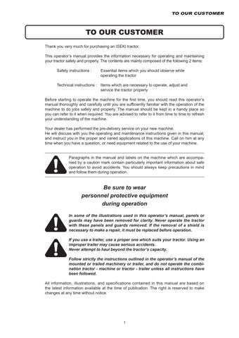
FIG. 4-5: Always park the tractor on level area when ever possible. If hillside parking is necessary, put block behind both rear wheels as shown.
NOTE: When stopping or parking Tractor, be sure brake is locked.
Cruise Control
Setting Cruise Control
FIGS. 4-6 & 4-7: Depress the forward HST pedal (1) and keep your intended speed. Push the cruise control knob (2) to set the speed. Then release the HST pedal.
WARNING: Cruise control should only be used in open spaces, without obstacles, with unobstructed view or traveling on the road. Be thoroughly familiar with cruise control operation before using.
IMPORTANT: To prevent mechanical failures, do not move the cruise control knob without pressing the forward HST pedal.
NOTE: Cruise control is not available in the reverse direction.
Releasing Cruise Control
Cruise control is released by depressing brake pedal (3).
Differential Lock
FIG. 4-8: When the differential lock pedal (1) is pressed, the rear axles are locked together so the rear wheels turn together at the same speed. This is especially important when you operate in loose soil or slippery conditions.
1.Stop the tractor.
2.Press and hold the differential lock pedal (1).
3. Slowly drive the tractor until the differential lock is engaged. You may have to slightly tun the tractor to engage the differential lock.
To disengage the differential lock, release differential lock pedal.
NOTE: Differential lock pedal will usually return to the off position when disengaged. If the differential lock pedal stays engaged because of a torque difference between the rear wheels, press the HST pedal slowly to release the lock pedal.
CAUTION: DO NOT use differential lock on hard surfaces or when transporting unit. DO NOT, engage with rear wheel(s) spinning as severe damage may result. DO NOT attempt to steer with the differential lock engaged.
4-WHEEL DRIVE
FIG. 4-9: Four-wheel drive models have a mechanically driven front axle. Engagement and disengagement of front drive axle is controlled by 4-wheel drive selector lever (1) on right side of tractor.
IMPORTANT: Prior to engaging or disengaging 4WD, Tractor stopped.
FIG. 4-10: When front axle is engaged, ground speed of front tires is slightly faster than the ground speed of rear tires. This is to assist steering when 4-wheel drive is selected.
For this reason, front axle must be disengaged when Tractor is transported of operated on a hard, dry surface. Failure to do so will result in rapid wear of front drive tires and possible driveline damage.
IMPORTANT: Always disengage front drive axle when operating in, conditions with minimal wheel slippage (DRY OR HARD SURFACES). If tire replacement is necessary, identical replacements must be installed to maintain correct front/rear axle ratio.
POWER TAKE OFF (PTO)
WARNING: PTO shafts and PTO driven implements can be extremely dangerous. Observe the following important points:
DO NOT operate Tractor without a PTO shield cover installed. The shield cover cap protects people from injury as well as the splines from damage.
Before attaching, adjusting or working on PTO driven Implements, disengage the PTO, stop the engine and remove the key. DO NOT work under raised equipment.
Before engaging a PTO-driven implement, ALWAYS carefully raise and lower the implement using Position Control. Check the clearance between shield cover and PTO shaft. Also check PTO shaft sliding range and articulation.
Ensure that all PTO safety shields are In place at all times. Do not step on the PTO shield cover.
Ensure that all PTO driven implements are in good condition and conform to current standards.
NEVER step across any driveline. Do not use PTO shield cover as a step.
DO NOT use the Tractor drawbar or the implement drawbar as a step.
NEVER use the driveline as a step.
NEVER wear loose fitting clothes.
Keep at least your height away from a rotating driveline.
Rear PTO Shaft
FIG. 4-11: A 6-spline 1-3/8(35mm) PTO shaft (1) is provided at rear of Tractor to provide power for mounted and other PTO driven equipment as required.
PTO cap must be installed when rear PTO is not in use.
Normal rear PTO shaft operating speed of 540 rpm is attained at 2 532 engine rpm.
IMPORTANT: When rear PTO is used with 3-point mounted equipment, it may be necessary to remove drawbar at rear of Tractor.
Some types of mounted equipment, when lowered, may allow PTO shaft to contact drawbar.
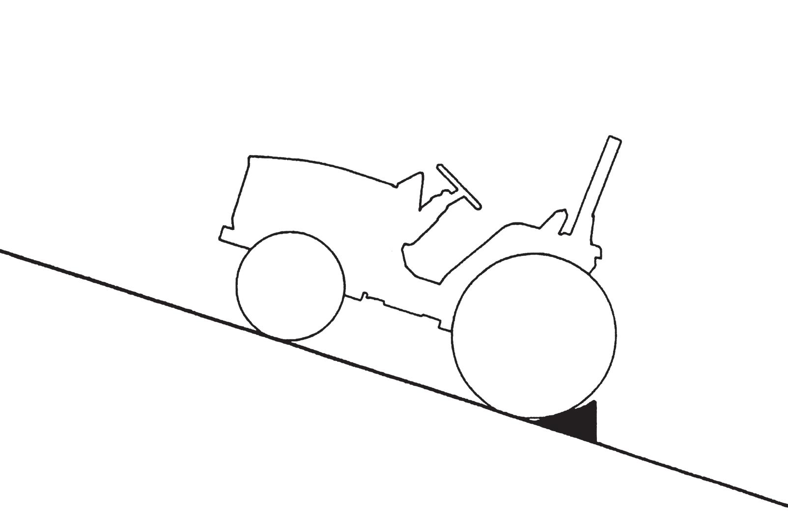
FIG. 4-12: Implement drive shaft shown connected to Tractor rear PTO shaft.
CAUTION: Make sure all PTO safety shields are installed on Tractor and equipment. Before cleaning or adjusting Tractor or PTO driven machine, STOP THE ENGINE AND DISENGAGE PTO.
Mid PTO Shaft
FIG. 4-13: Mid PTO (1) is forward-facing shaft located at underside of Tractor. The mid PTO is used to operate certain mid or front-mounted implements. A1”(25.4mm) 15 spline shaft is used.
Mid PTO cover must be installed when use of mid PTO is not required.
2 000 rpm @ 2 476 engine rpm
CAUTION: Make sure all PTO safety shields are installed on Tractor and equipment. Before cleaning or adjusting Tractor or any PTO driven machine, STOP THE ENGINE AND DISENGAGE PTO.
PTO Operating Controls
FIG. 4-14: Rear PTO and mid PTO are both controlled by PTO clutch lever (1).
Rear PTO selector lever (2) is used to select position of rear PTO drive gears.
To select rear PTO - Make sure PTO clutch lever (1) is OFF, and then move rear PTO selector lever (2) rearward to “540” position to engage gear.
To engage PTO - Move the PTO clutch lever forward.
NOTE: When the PTO clutch is engaged, reduce engine speed.
To disengage PTO - Move the PTO clutch lever backward.
Mid PTO selector lever (3) is used to select position of mid PTO drive gears.
To select mid PTO - Make sure PTO clutch lever (1) is OFF and then move mid PTO selector lever (3) backward to “2000” position to engage gear.
To engage PTO - Move the PTO clutch lever forward.
NOTE: When the PTO clutch is engaged, reduce engine speed.
To disengage PTO - Move the PTO clutch lever rearward.
NOTE: Rear and Mid PTO can be operated at the same time or independently.
3-POINT LINKAGE
3-point linkage combines tractor and implement into one working unit. Implement position and raising are controlled hydraulically. In addition, implement weight and loads impose downward pressure at Tractor rear wheels to increase traction.
Linkage Controls
FIG. 4-15: Control quadrant, to right of operator’s seat, controls the system to provide the following linkage control functions:
Position Control - Maintains Linkage position at constant height in relation to the tractor. As 3-point linkage position control lever (1) is moved backward, linkage and implement are raised. Moving lever forward will lower hitch to selected position. Each lever setting provides a specific linkage and implement position.
CAUTION: Use 3-point linkage position control lever (1) when attaching or detaching implements.
FIG. 4-16: Lowering rate control knob (1) controls “rate of drop” of 3 point linkage and implement. Turn the knob (1) clockwise to slow the dropping rate. Turn the knob (1) counterclockwise to increase the dropping rate. Turning the knob (1) clockwise fully will lock implement in raised position.
CAUTION: When working on or around mounted implements, always lower to ground prior to work. If implement must be raised, always block implement and lower links securely.
Rear Linkage
FIG. 4-17: Linkage consists of several major components for implement attachment and operation:
Lower Links (1) - Primary attaching points to lower implement pins.
Lift Rods (2) - Connect lower links to hydraulic lift arms for raising/lowering lower links. The lift rod connected to the right lower link has provisions for leveling the implement (side to side).
Check Chains (3) - Reduce side sway of implement.
Top Link (4) - Adjustable turnbuckle type to level implement (front to rear).
CAUTION: Make sure that all pins after adjustment is made. Always use pins supplied with the tractor.
WARNING: Stay clear from the area of the rear linkage system when controlling it.
Attaching Implements
CAUTION: Always use POSITION CONTROL to attach/detach implements to provide precise control of hitch.
FIG. 4-18: Back the tractor to implement by centering with implement linkage frame.
Raise or lower the linkage by using position control lever (1) and align left lower link end with corresponding implement attaching pin.
Lock the brakes, shut off the engine and remove the key.
FIG. 4-19: Move the ball end of the left lower link (1) over the implement pin and secure with a retainer pin. Adjust the height of the right lower link with the turn buckle (2) of lift rod.
Connect the right lower link (3) to the implement with a retainer pin.
Attach the top link (4) to the top of the implement hitch frame.
Turn the center barrel section of the top link to level the implement from front to rear.
Use the turnbuckle and top link to adjust for level operation.
Make sure all adjustments are secured. Adjust the check chain (5) evenly on each lower link to reduce the side play to the desired level.
IMPORTANT: With some mounted implements, it will be necessary to remove drawbar at rear of Tractor to permit implement to be raised and lowered without obstruction.
Certain implements require minimal side-play. Check chain (5) at each lower link should be evenly adjusted to reduce side-play to desirable level. Do not remove all side-play as lower link damage may result.
NOTE: The amount of side-play (check chain looseness) is dependent upon implement and type of operation.
Normally 50mm of total side movement is desired, 25mm to each side of Tractor center line.
Using Position Control
FIG. 4-20: Type of Work - Attaching/detaching implements and other operations requiring implement to be kept at constant height above ground. Also used with implements equipped with gauge (support) wheels.
FIG. 4-21: Lever Positions - Use 3-point linkage position control lever (1) to adjust hitch and implement position.
To Begin Work - Align Tractor and implement in field and move position control lever (1) forward (toward DOWN). Adjust implement height using position control lever (1) as desired. Note the location of lever.
When Turning - Move position control lever (1) rearward (toward UP) to raise implement. Finish turning and return lever to previously set position to resume operation.
To Finish Work and Transport - Move position control lever (1) fully rearward in quadrant.
FIG. 4-22: When using different weights of implements, “rate of drop” of 3-point linkage and implement can be controlled with the “Lowering Rate Control” Knob (1).
Turn knob clock wise to slow drop rate, counterclockwise to increase drop rate. Turning knob fully clockwise will lock implement in raised position.
CAUTION: When using mounted implements with the PTO driveline, make sure:
PTO drive shaft has minimum 51mm engagement of telescoping sections, at all hitch/implement positions.
Hitch height during raising does not bind drive shaft universal joints due to extreme drive shaft length,
PTO drive is disengaged during transport.
Detaching Implements
CAUTION: Always use POSITION CONTROL to attach/detach Implements to provide precise control of hitch.
FIG. 4-23: Select a level area to detach and store the implement. Lower implement to ground by moving position control lever to DOWN. If necessary, adjust leveling turn buckle on right lift rod to level implement on ground.
Shut off engine, securely lock brakes and remove key from Tractor.
Disconnect implement PTO drive shaft (as applicable). Detach top link from implement and place in storage position on Tractor by engaging spring on top link in slot in rear center panel.
NOTE: Lengthening or shortening of top link may be required to permit disconnection from implement.
Disconnect lower links from implement pins. Make sure check chains (1) are readjusted to prevent tire interference.
Take position in operator’s seat, start engine and drive tractor clear of implement.
Cutting Height Control Knob
FIG. 4-24: The cutting height control knob (1) adjusts the cutting height for the mid mount mower deck.
CAUTION: When operating without mid mount mower deck, the linkage for mower deck must be in fully up position by using position control lever. Also, Turn the cutting height control knob to counterclockwise and to set highest position.
How to adjust Height Control
FIG. 4-25: When attaching the mid mount mower, it can be set to the desired height by adjusting cutting height control knob (1) without using the gauge wheel.
When adjusting cutting height with cutting height control knob, set the position of gauge wheel to the lowest position. Adjustable in 7 stages by cutting height control knob. Turning knob clockwise will raise the cutting height of mower deck and counterclockwise will lower the cutting height of mower deck.
Procedure
FIG. 4-26 & 4-27: Adjustable in 7 stages by cutting height control knob. Turning knob clockwise will raise the cutting height of mower deck and counterclockwise will lower the cutting height of mower deck.
・When changing cutting height, raise the mower deck to the highest position by control lever before turning the cutting height control knob.
・The knob cannot be turned when the mower deck is in the lowest position.
NOTE: The height adjust gauge may not show the practical cutting height.
The table of cutting height
Joystick Lever (J type)
FIG. 4-28: The joystick lever (1) is located to the right side of the seat.
FIG. 4-29: The joystick control lever has six positions:
Lever position Function
A: Backward Lift arm up
B1: Forward Lift arm down
B2: Double forward Floating
C: Left Bucket curl
D1: Right Bucket dump
D2: Double right Bucket quick dump
Joystick Hydraulic Ports (J type)
FIG. 4-30: Hydraulic ports are located above the right step.
NOTE: Adaptors and hoses are not originally equipped to J type. Optional parts code for adaptors and hoses is “1739-512-600-20”.
Output port Cap color Function
1+ Red Loader boom lift
1- Black Loader boom lower and loader boom float
2- Green Bucket curl back
2+ Blue Bucket dump and bucket fast dump
Procedure
FIG. 4-31: Move the joystick control lever to operate the auxiliary valve. The auxiliary valve supplies oil to the hydraulic ports.
Move the joystick control lever rearward and forward to move the A/B spool in the control valve.
Move the joystick control lever side-to-side to move the C/D valve spool and cvontrol the loader bucket position. When used with a blade, this controls angling (lift and right).
All positions except float will return to the neutral position when lever is released.
(A) Move rearward to lift the loader boom or other attachement
(B1) Move forward to lower the loader boom or other attachment.
(B2) Push completely forward to put into the float position. This will let attachment follow ground contours.
(C) Move left to curl back the bucket.
(D1) Move right to dump the bucket.
(D2) Push completely to the right to put the valve in the regenerative position. This lets the bucket to dump quickly.
Joystick Lever Control Lock (J type)
FIG. 4-32: The joystick lever has a lockout hat will keep the joystick in the neutral position.
・To lock the joystick, move the lockout lever up and to the left.
・To unlock the joystick, move the lockout lever to the right and down.
ROLL OVER PROTECTIVE STRUCTURE (ROPS) (R Type)
FIG. 4-33: This Tractor is equipped with a roll-over protective structure (ROPS) (1). Seat belt must be fasten when the ROPS is in the upright position.
The ROPS can be folded down only in the limited work such as going into and out from building, and work within orchard, hop or vineyard. After the work, return the ROPS to the up right position.
How to fold down ROPS
FIG. 4-34: Right and Left side ROPS: Loosen the pushing bolt (2), and remove clevis pins (3) and link pins (4). When the pins are removed, the upper portion of the ROPS can be folded down to the rear. Right side ROPS: Then fix the upper portion of the ROPS with clevis pin (3) and link pin (4).
WARNING: If ROPS is damaged during operation, do not weld, bend or straighten. Make sure all components are in correct working order to provide the intended protection.
WARNING: Except for the limited work such as going into and out from building and work within orchard, hop or vineyard, do not operate the tractor with the ROPS folded down. Otherwise, this may result in serious injury when the tractor rolls over.
CAUTION: When folding down or returning the ROPS to upright position, grab the limited area, between two labels (5), of the ROPS. (Refer to FIG. 4-33)
CAUTION: Do not use the seat belt when the ROPS is folded down.
How to install ROPS
FIG. 4-35: Carefully lift lower ROPS frame legs (6) into position on top of fenders.
Install 8 pieces of M12 nuts (7) with spring washers to secure the lower ROPS frame to the fenders.
FIG. 4-36 & 37: Position the upper frame (8) on top of lower ROPS frame. Install shoulder bolts (9) at the rear of the frame with washers (10) and nuts (11) to the inside. Install link pins (3) and clevis pins (4) at the front of the frame, with link pins to the inside.
NOTE: Each clevis pins and link pins are fitted with O-ring to prevent rattling. In addition, a pushing bolt (2) is installed to reduce noise.
Tighten all ROPS hardware at this time, using the following torque chart:
EXTERNAL AUXILIARY HYDRAULICS (V Type)
FIG. 4-38: V type has three external auxiliary hydraulic valves. All levers are spring loaded to the neutral position.
1st external auxiliary hydraulic lever (1) - is for lifting and lowering the collector. Lever (1) also has free flow position. For lifting and lowering collector. This lever has free flow position.
2nd external auxiliary hydraulic lever (2) - is for dumping the collector.
3rd external auxiliary hydraulic lever (3) - is for lifting the mower deck.
CAUTION: Always lower implement to ground, shut off engine and relieve system pressure (by operating control levers with engine off) before connecting or disconnecting implement hoses.
EXTERNAL AUXILIARY HYDRAULICS PORTS (V Type)
FIG. 4-39: Ports for external auxiliary hydraulic valves (1), (2) and (3) are located at the right back side of the seat.
NOTE:Adaptors and pipes are not originally equipped to V type. Optional parts code for adaptors and hoses is “1739-512-400-10”.
Rear Hitch
FIG. 4-40: Rear hitch (1) at rear of Tractor allows towed implements to be attached to Tractor. Tractor does not have any trailer braking system. Follow strictly the instructions outlined in the operator’s manual of the mounted or trailed machinery or trailer, and not to operate the combination Tractor – machine or Tractor – trailer unless all instructions have been followed. Do not use non-genuine parts for towing. Otherwise, unexpected accidents may occur.
Keep the maximum vertical load on the rear hitch, related to the rear tyre size and type of hitch. (TABLE 5 & 6)
TABLE 5: Specification of rear hitch (TRH-1739) e13*2015/208*2018/829
Type approval No.
NS*00047*01
Maximum horizontal load Not applicable
Towable mass 1000 kg
Maximum permissible vertical load on the coupling point 500 kg
TABLE 6: Maximum vertical load
TXGS24
TRH-1739
Right brake pedal Left brake pedal Right brake pedal Left brake pedal Tire Size Without front weight (kg) With front weight (kg)
Rear Rear ROPS
Keep the permissible towable mass. (TABLE 7) When towing trailer, stay clear from the area between tractor and trailed vehicle.
TABLE 7: Permissible towable mass
TRH-1739
Towable mass
Total technically permissible masses of the tractor - trailer combination for each configuration of trailer braking (kg) R- and S category vehicle
Total technically permissible towable mass (kg)
Front Loader Fixation Point
Consult your ISEKI Dealer concerning the fixation points on Tractor for the Front Loader. Appropriate frames between the rear axle and the front frame might be necessary to obtain robust safety.
FALLING OBJECTIVES PROTECTIVE STRUCTURE (FOPS) & OPERATORS PROTECTION STRUCTURE
(OPS) FIXATION POINT
Consult your ISEKI Dealer concerning the fixation points on Tractor for the FOPS & OPS.
Txgs24
7 Pins Socket
FIG. 4-41: 7 pins socket (1) is located on the left side of the tractor.
CAUTION: Select the proper size electric wire for auxiliary power supply. Insert a fuse to the wiring for the attachment when using the smaller capacity electrical wires than the proper size. Otherwise, the fuse cannot protect the wiring if there is a short circuit, and may result in the burning of the electric wiring and cause fire.
Electric Power Outlet 12v Socket
FIG. 4-42: TXGS24 is equipped with a 12V socket outlet (1). TO access the 12V socket, open the cover on the storage compartment on the right fender and remove the cap on the 12V socket.
Disconnect your accessory from the 12V socket when not in use.
CAUTION: Do not connect a lamp or a load of more than 120 watts. Do not use as a cigarette lighter.
Towing
Ask your ISEKI Dealer for towing Tractor as much as possible. If such cases as listed below, call your ISEKI Dealer as transmission might be broken.
・Although the engine runs, Tractor cannot start to move.
・Unusual noise occurs.
FIG. 4-43: Hook up the rope to the front hitch (1). The distance between towing vehicle and Tractor should be less than 5m. Move the rage shift lever to the neutral position. Release the parking brake lock.
Jacking
When jacking Tractor, place the Tractor on level, hard ground which is sufficiently illuminated, otherwise unexpected accidents may occur. Follow the instructions listed below:
・Apply parking brakes.
・Disengage all PTO.
・Place all gear shift levers in neutral.
・Remove the starter key.
・Place the jack on level.
FIG. 4-44: When raising the rear axle, suitable shims (1) should be wedged between the front axle and the front frame.
FIG. 4-45: When raising the front axle, the jacking point is the front axle bracket (2). When rasing the rear axle, the jacking point is the rear frame (3).
MAINTENANCE & ADJUSTMENT
SPECIFICATIONS & CAPACITIES
Engine
Use equivalent in the appropriate SAE viscosity. Oil must meet of exceed; MILL-46152 requirements, API Service
NOTE: Change intervals stated above are for normal usage. Due to adverse operating conditions that may be experienced (extremely dusty of muddy), change intervals may need to be more frequent.