20 minute read
PERIODIC MAINTENANCE SCHEDULE


: Inspect, replenish or adjust : Replace : Clean or wash : Replacement or servicing at authorized service facility recommended.
TABLE 7: Maintenance table
1Engine oil
2Engine oil filter
3 Air cleaner element
4 Radiator & reserve tank coolant
5Radiator hose
6Fuel filter element
7Fuel pipe / hose
8Fan belt
Remarks
Replace after initial 50 hours and then after every 200 hours.
Replace after initial 50 hours and then after every 400 hours.
Clean or replace as required. Replace once a year.
Replace once every 2 years.
Replace once every 2 years at your dealer.
Clean as required. Replace once a year or every 400 hours.
Replace as required.
Replace as required. Inspect every 100 hours.
Replace after initial 50 hours and then after every 400 hours. 10
9Transmission oil
Wash after initial 50 hours and then after every 400 hours. Replace as required. 11Front
Inspect every 200 hours. Replace every 600 consult
Tractor
: Inspect, replenish or adjust : Replace : Clean or wash : Replacement or servicing at authorized service facility recommended.
Remarks
20Electrical wiring Inspect once a year. Inspect once every 2 years at your dealer.
21 Battery condition Charge or replace as required.
22Light device Inspect once a year.
23Greasing Grease before & after operation
Service Access
CAUTION: Shut off engine before servicing tractor. Engine hood must be secured prior to operating tractor.
To access radiator, battery and engine components, engine hood can be opened.
Opening / Closing Engine Hood
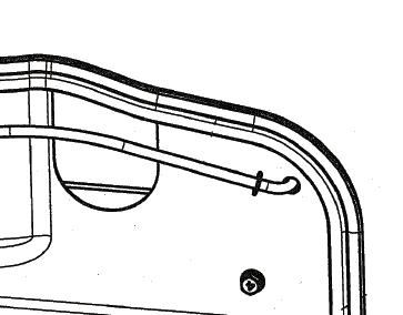
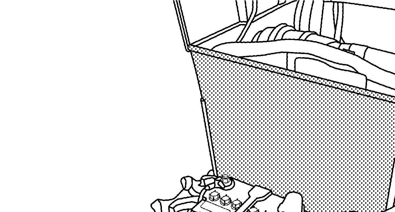
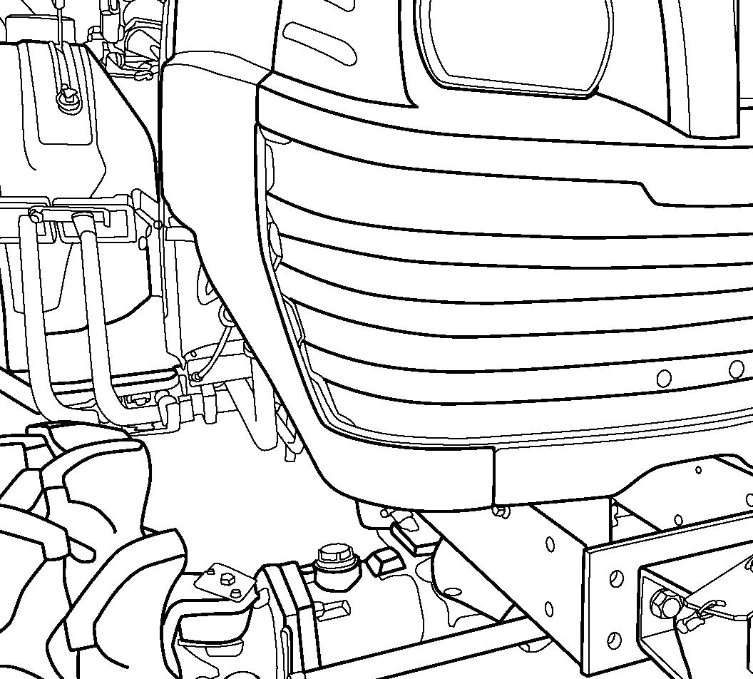
FIGS. 88 & 89: To open the hood, insert the tool (1) to the hole on front grill, and push it.
To close the hood, lift up lightly the front of the hood, push the lock lever (2) and pull down on the front of the hood. Make sure that the open lever is in the locked position.
Lubrication Details
Grease Fittings
Lubricate all grease fittings (refer to TABLE 6) every 50 hours of operation using No. 2 multipurpose lithium base grease. Clean the grease gun and fittings before and after greasing to prevent contamination from dirt.
NOTE:When operating in muddy or extremely wet conditions, lubricate the fittings daily.
Engine Oil & Filter
DANGER: Muffler tail pipe is extremely hot just after operation, so take care not to touch it to avoid burns. Be sure to wear gloves before checking engine oil level.
Engine oil should be changed after the first 50 hours of operation and then every 200 hours thereafter. Engine oil filter should be changed after the first 50 hours of operation and then every 400 hours thereafter.
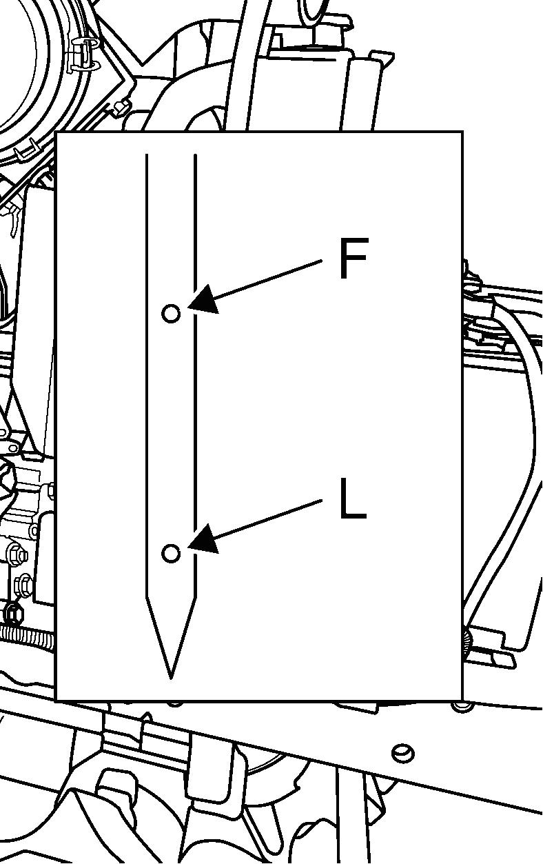
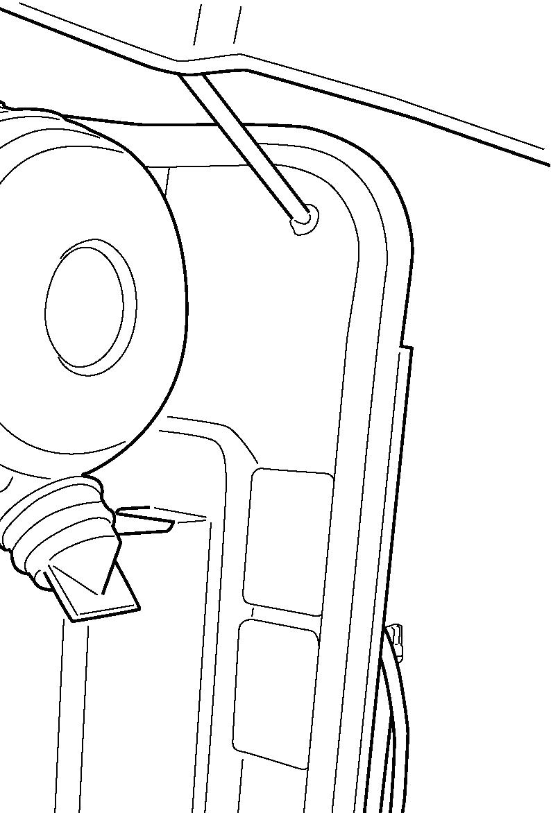
FIG. 90: To Check Engine Oil Level - Park tractor on level ground. Make sure to allow the engine to cool sufficiently before checking the engine. Pull out the dipstick (1) and check that oil level is between upper limit F and lower limit L on the dipstick. Wipe off the dipstick, momentarily reinstall it in the engine and check oil level again.
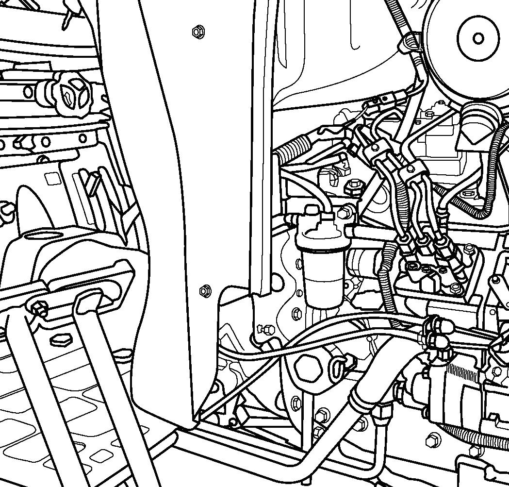
FIG. 91: To add oil, open the engine hood and remove the filler cap (2). Add oil using a funnel to prevent oil from spilling. After adding oil, make sure that oil level is between upper limit and lower limit on dipstick.


NOTE: Add oil slowly to assist in venting air from the crankcase.
FIG. 92: To Change Engine Oil - Operate the tractor until oil is adequately warmed. Remove the drain plug, 3, from the engine and allow all oil to drain out.
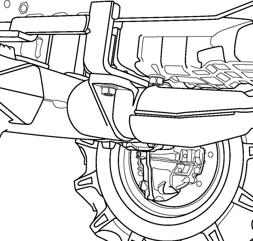
Reinstall the drain plug and fill the engine crankcase through filler opening (2) to the upper limit on the dipstick.
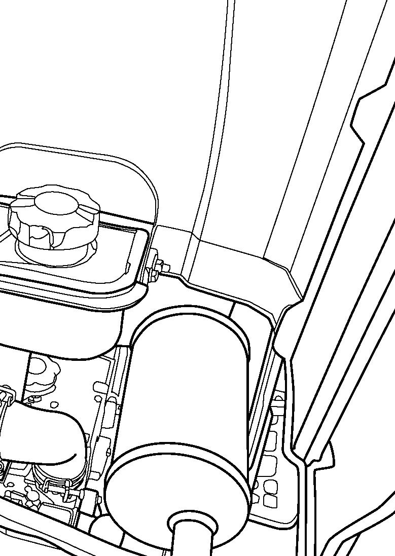
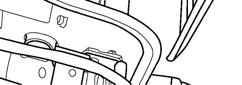
FIG. 93: To Replace Engine Oil Filter - Remove the oil filter (4) from the engine and take the old filter to a proper disposal point. Make sure that the original filter gasket has been removed.
Lubricate the new gasket on the new element with clean engine oil. Turn in the new element until its sealed face comes in contact with the O-ring. Use a filter wrench to further turn in the cartridge by 3/4 turn.
Clean spilled oil and refill the crankcase. Start the engine, check for leaks and replenish oil level as required.
IMPORTANT : Engine warranty is valid only when original engine maker manufacturer’s oil filter is used.
Transmission Oil & Filters
Transmission oil lubricates the transmission, center housing, and rear axles and also serves as hydraulic fluid. Transmission oil should be changed and the filter should be cleaned after the first 50 hours of operation and then every 400 hours thereafter.
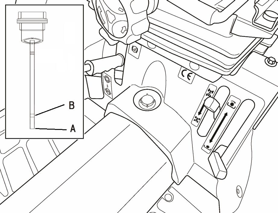
FIG. 94: To Check Transmission Oil Level - Park the tractor on level ground. Pull out the dipstick (1). Oil level should be indicated between the upper limit (A) and the end of dipstick (B). Oil level is replenished, as necessary, by removing the filler plug (2) and adding oil through the filler opening.
NOTE: Adding oil to the transmission will also maintain correct oil level in the center housing and rear axles.
FIG. 95: To Replace Transmission Oil - Remove the drain plug (3) and the final drive plugs (4) on each axle. Completely drain oil from the transmission case.
IMPORTANT: Completely lower the 3-point hitch prior to draining transmission oil. When completely drained replace and tighten all drain plugs. Refill with oil as outlined above.
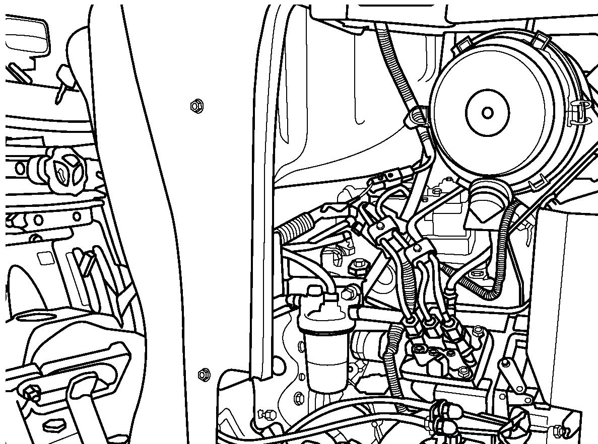
FIG. 96: To Clean Transmission Oil Filter (Suction) - Clean the transmission oil filter while oil is removed. Unscrew the filter (5) from suction pipe. Clean it in solvent or kerosene, dry thoroughly and reinstall. And if you find damage of filter, replace it with new one. Make sure O-rings are not damaged.
Refill the filter with clean oil to level as detailed. Start the tractor and allow the engine to idle several minutes while operating the hydraulic controls. Shut the engine off, lower the 3-point hitch and recheck oil level. Replenish transmission oil as necessary. Check for leaks and correct as necessary.
NOTE: After transmission oil has been replaced, or when the tractor restart after a long term of storage, or when the hydraulic system does not operate properly, consult your dealer.
Front Axle Oil
Front drive axle has a common oil level for front differential housing and each wheel reduction unit. Oil level should be checked every 200 hours of tractor operation and replaced after every 600 hours.
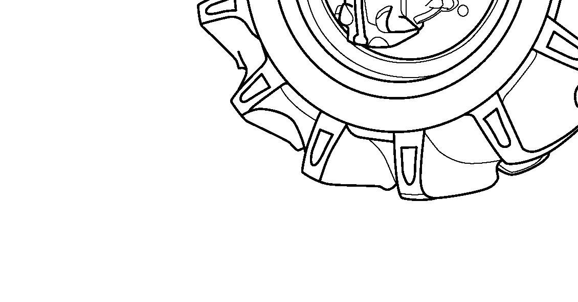
FIG. 97: To Check Oil Level - Park the tractor on level ground and then remove the oil level plug (1) Oil should be level with or slightly below the level plug opening. Remove the fill plug (2) and add oil until oil is expressed from the level plug opening. Replace the level plug and fill plug.
To Change Oil - Park the tractor on level ground. Remove the drain plug (3) from both wheel reduction units. When all oil has drained out, replace the drain plugs and fill the housing to the level plug opening. Replace the level plug and filling plug.
Cooling System
CAUTION: Do not open the radiator cap except when checking or replacing the coolant. Make sure to allow the engine to cool sufficiently before opening the cap. If the cap is opened while the engine is hot, coolant may be discharged, resulting in a burn or other injury.
Checking / Replenishing Coolant
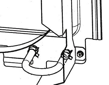
FIGS. 98 & 99: Cooling system is filled at factory with anti-freeze solution to protect the engine and radiator to -37 ˚C (-34 ˚F). Cooling level should be maintained to 10 mm (0.394 in) upper from the radiator cap (1) Check coolant as a precaution against freezing.
Coolant should be replaced if it becomes contaminated with rust or sludge. Loosening the radiator cap (1) for assisting draining, and pull out the radiator hose (2) to drain the coolant in the radiator.
Drain away the coolant from the engine by loosening the water drain cock (3) on the right hand of cylinder body.
After draining coolant, tighten the radiator hose and the water drain cock. Use clean drinking water as a coolant, fill up the radiator with the coolant until the level comes up to the filler port neck. Fill gradually to prevent air entry.

With the coolant poured, start the engine about 5 minutes at a low idle speed, then the air contained in the coolant circuit is bled. The coolant level will drop. Stop the engine to replenish with the coolant.
NOTE: Before adding new coolant, flush inside of the radiator and engine block with clean water.
The radiator and engine must be drained if freezing temperatures are expected and the cooling system is not filled with sufficient to provide adequate protection from freezing.
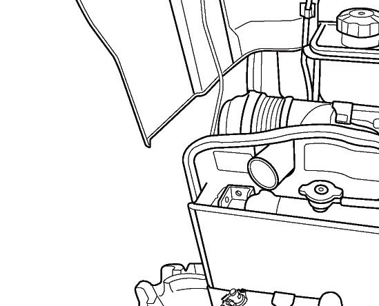
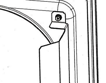
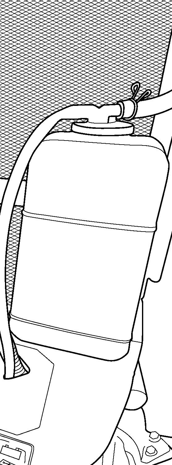
FIG. 100: The radiator is provided with a reserve tank (4) to maintain the coolant in the radiator at the proper level. Check the level in this reserve tank during the daily inspection.
Make sure that the coolant in the reserve tank is between FULL and LOW. If the coolant level is near to low, add coolant to the reserve tank up to the FULL level.
When the coolant level is below the LOW level, remove the radiator cap (5) after allowing the engine to cool sufficiently. Add coolant and make sure that there is an adequate amount of coolant in the radiator.
IMPORTANT: Do not fill the reserve tank higher than the FULL level. This will prevent the radiator from functioning optimally, and may result in leakage of coolant.
Use of Anti-Freeze
Freezing of the coolant may result in damage to the engine. Mix in 50/50 anti-freeze (Long Life Coolant) when the outside temperature will drop below 0 °C (32 °F) during the winter.
The mixture ratio of anti-freeze differs depending upon the anti-freeze manufacturer and temperature. Follow the instruction for the anti-freeze.
Cleaning Radiator
WARNING: Make sure to stop the engine when cleaning the radiator. Placing your hands in this area while the engine is operating may result in serious injury.
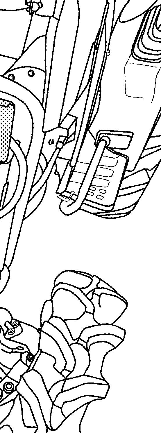
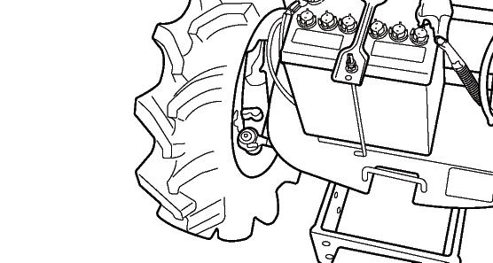
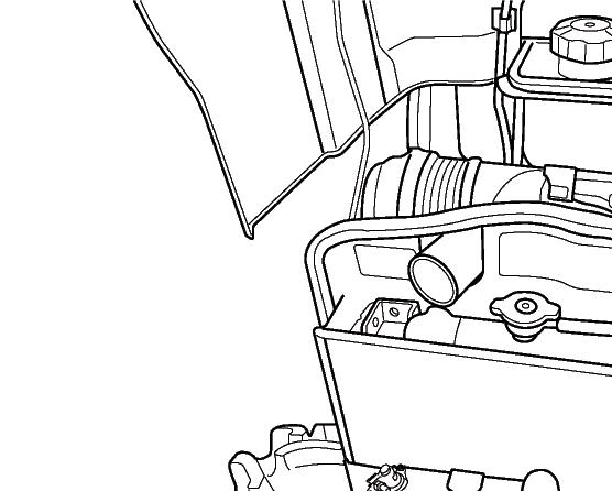
FIG. 101: Cleaning Radiator Net
When the tractor is operated in fields or at night, radiator net may become clogged with grass, straw, insects and other matter. Park the tractor on level, and open the hood. Pull out the radiator net (1) and clean it.
Cleaning Radiator Core
Wash away any dirt or other foreign matter in the fins and the radiator core (2) with water.
IMPORTANT: When the radiator becomes clogged, it will overheat, resulting in increased oil consumption.
Be careful not to apply high pressure water directly to the radiator as this may result in deformation of the fins.
Do not directly spray water on the electrical wiring or electrical parts around the engine.
Fan Belt
FIG. 102: Correct fan belt tension helps to insure adequate coolant flow through the cylinder block and radiator. The belt is correctly tensioned when belt deflection is approximately 5 mm (0.197 in) as shown at “x” when thump pressure is exerted at the center of belt span.
CAUTION: Due to muffler position, allow it to cool before checking or adjusting fan belt tension.
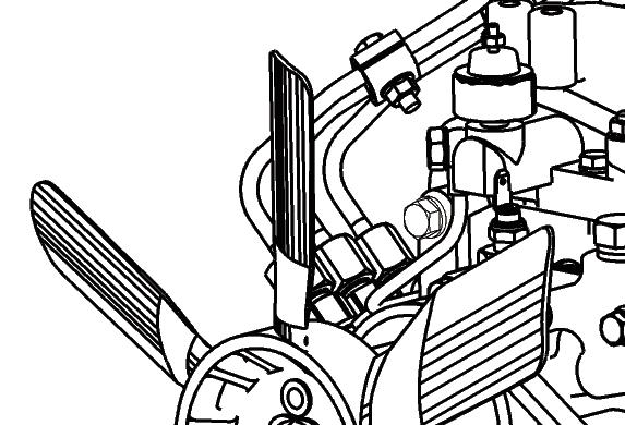
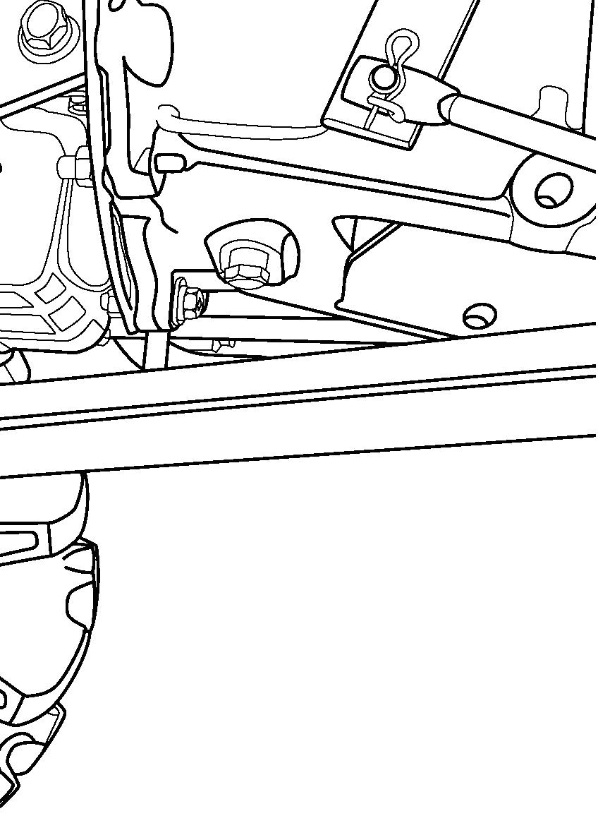
FIG. 103: To adjust belt tension, loosen the alternator pivot bolt and nut (1) and tensioning bracket bolt (2). Pull outward on top of the alternator to correctly tension belt and tighten the bolt (2) first and then tighten the pivot bolt (1).
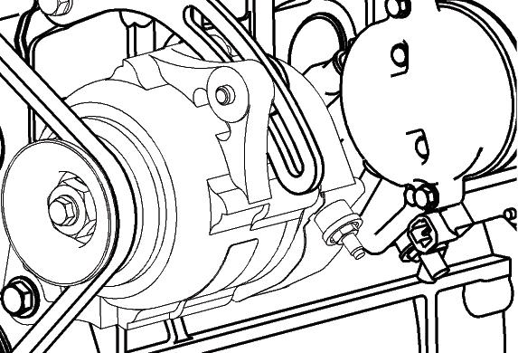
IMPORTANT: Do not pry against the alternator housing or pulley. Carefully pry against the alternator mounting flange to prevent damage.
Engine Air Cleaner
IMPORTANT: Never operate the engine with the air filters removed.
Cleaning / Replacing Air Cleaner Element
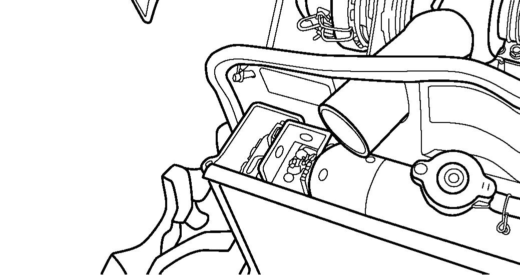
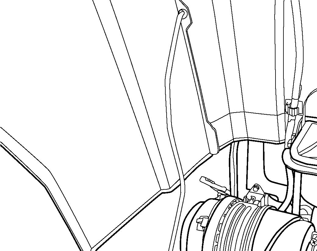
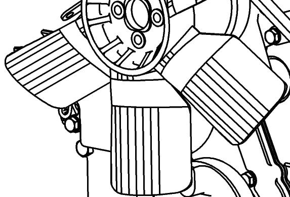
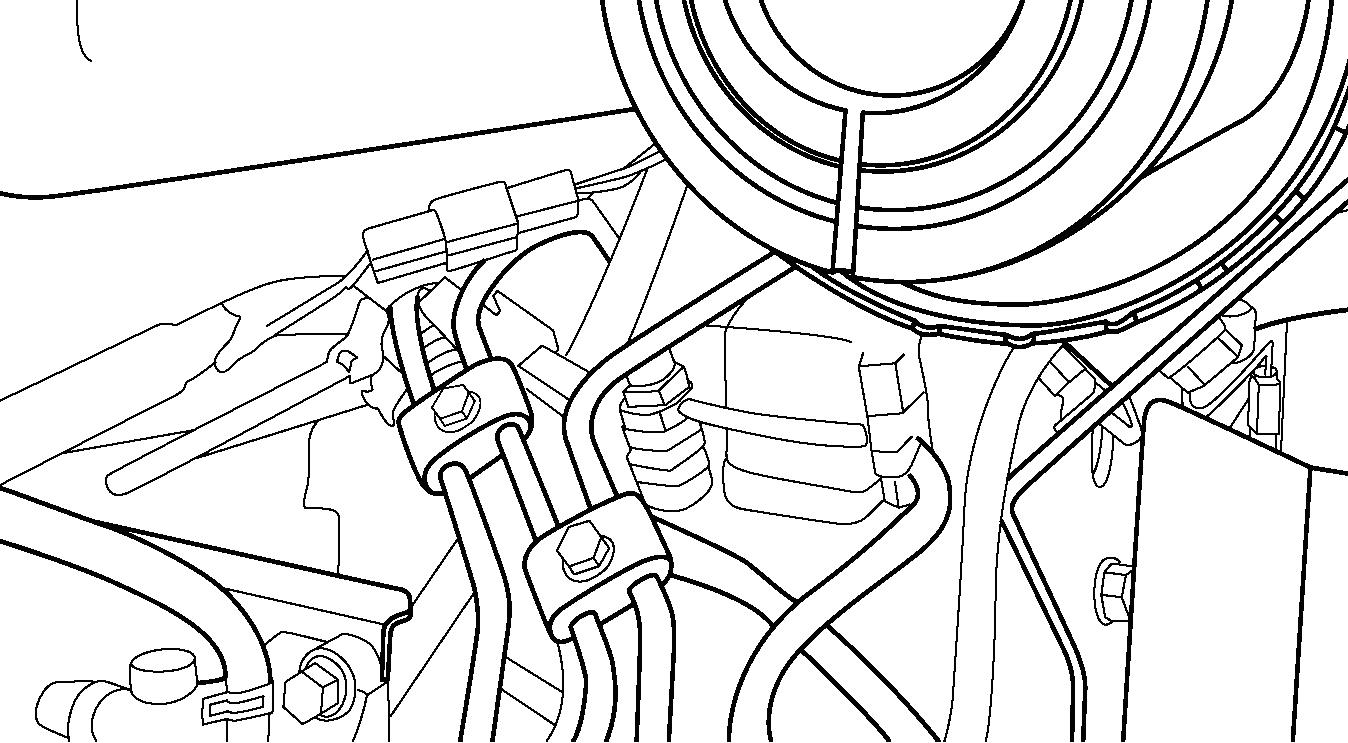
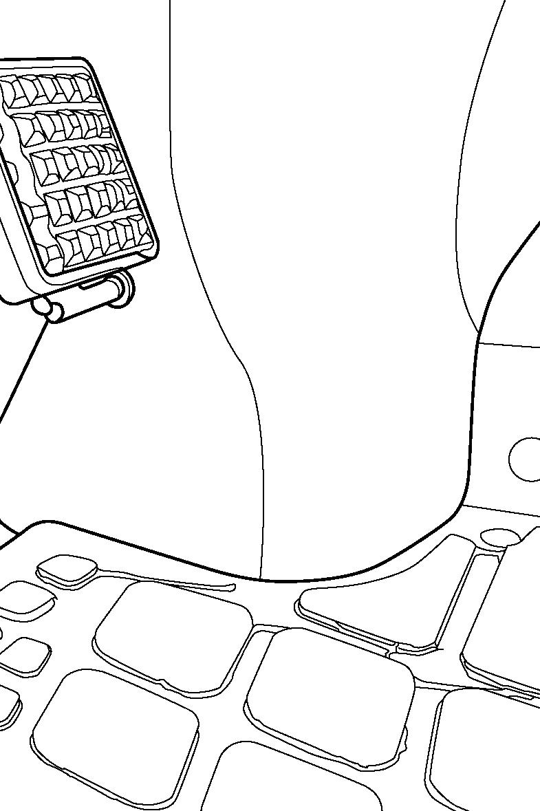
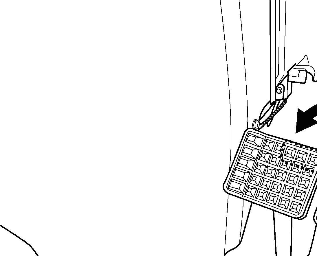
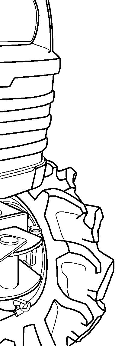
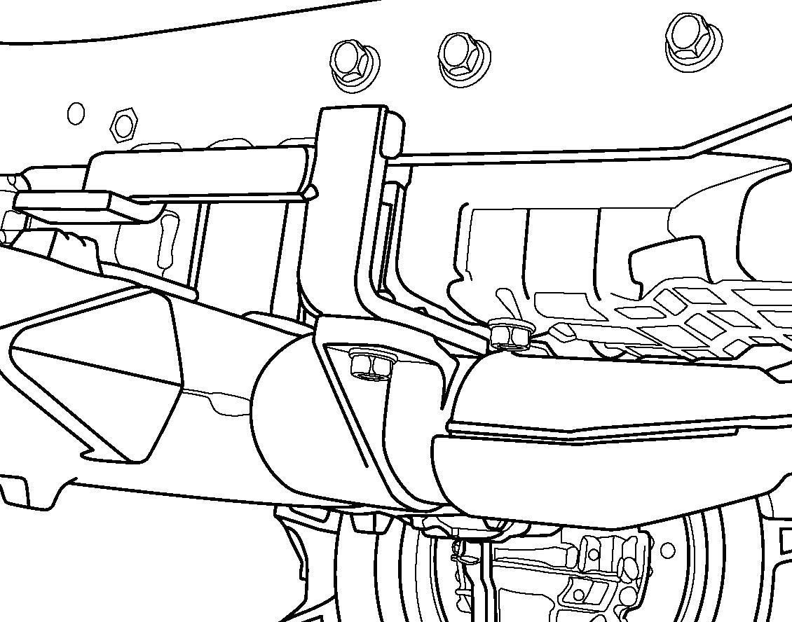
FIGS. 104 & 105: The engine air cleaner (1) is located above the engine. To service the engine air cleaner, gain access, open the hood.
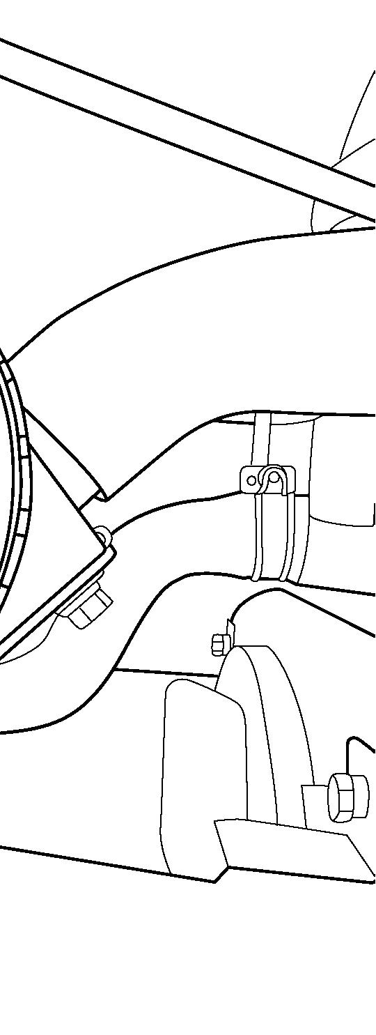
Press the evacuator valve (2) to discharge any dirt inside. Release clips (3). Remove cover (4) and take the element (5) out of the air cleaner.
If there is moisture, wipe the inside of the air cleaner (1). If the element (5) is damaged, replace it.
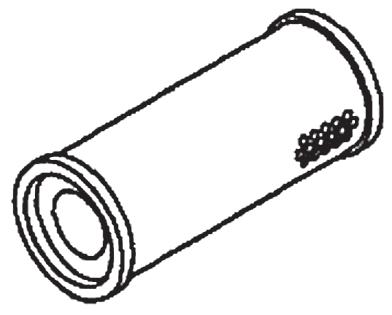
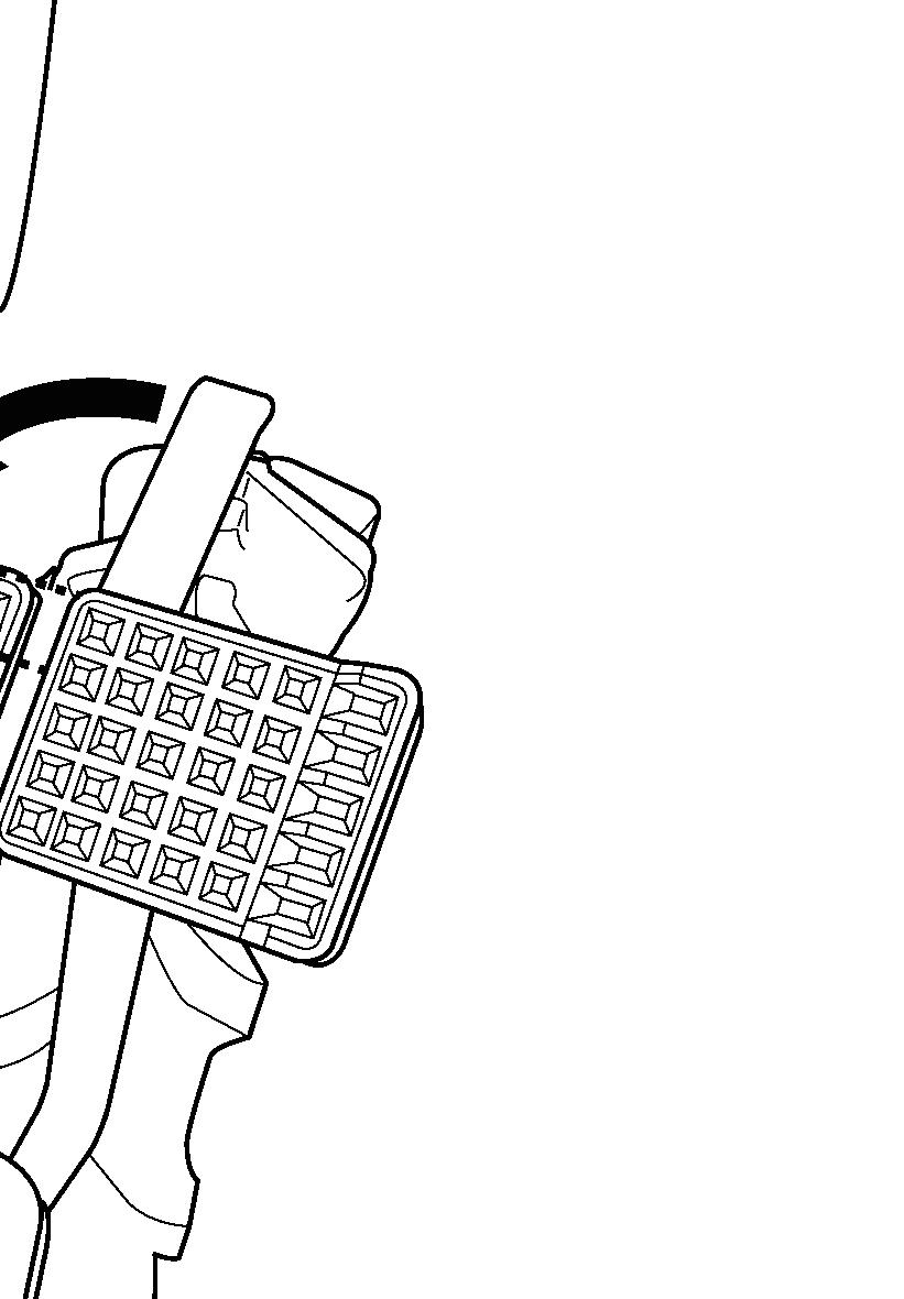
FIG. 106: Element can be cleaned (if in serviceable condition) using following procedures:
• Using compressed air not to exceed 200 kPa (30 psi) from the inside of the element, remove loose dirt, grass, chaff, etc. Be careful not to damage element pleats with air flow.
• If the element is coated with oil or soot:
1.Prepare solution of warm water and non-foaming detergent.
2.Soak the element for 30 minutes.
3.Agitate the element in solution until oil and soot are loosened.
4.Rinse the element until rinse water is clear.
5.Allow the element to completely dry. Do not dry by using compressed air or heat.
• After cleaning (or washing) the element examine for pin holes, punctures, or tears. If the element paper, canister or seal show any signs of physical damage, the element must be replaced.
NOTE: Replace an element which has already been washed 5 times.
IMPORTANT: Do not hit the filter element against a rock, concrete or other hard item when cleaning it. This may result in damage or deformation of the filter element, inhibiting engine performance.
Fuel System
Use only clean diesel fuel of correct grade. Introduction of water or dirt into the fuel tank or other portion of the fuel system can cause repeated plugging of the fuel filter and possible injection pump and injector damage.
IMPORTANT: Do not tamper with injection pump or injector adjustment. Such tampering will spoil engine itself and / or cause severe engine damage. And warranty will not be covered for the machine with such tampering.
Fuel Filter
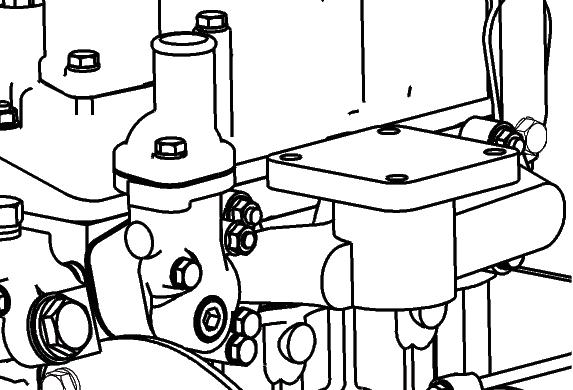
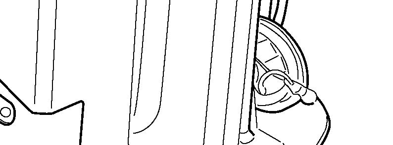
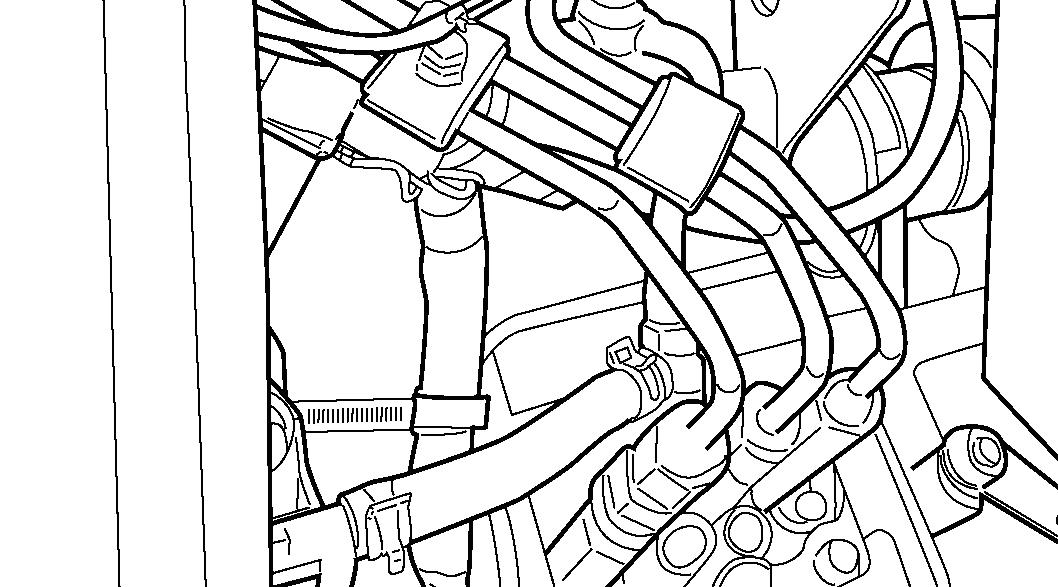
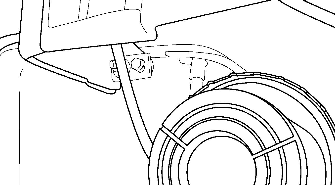
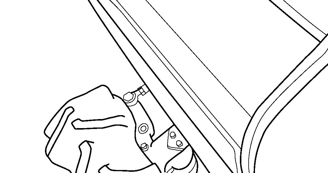
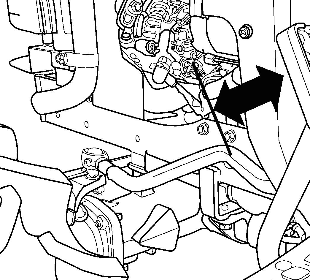
FIG. 107: Fuel filter assembly (1) is located at the right side of the engine, and is used to strain impurities from fuel before fuel reaches the injection pump.
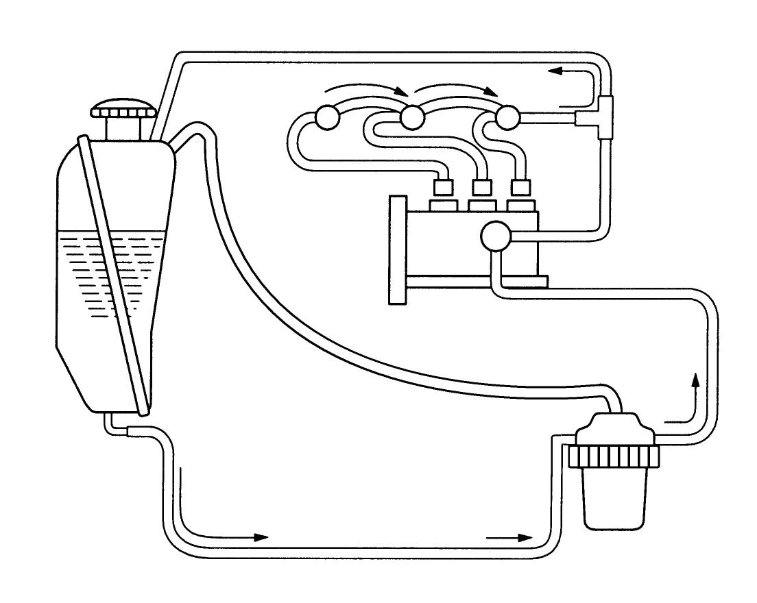
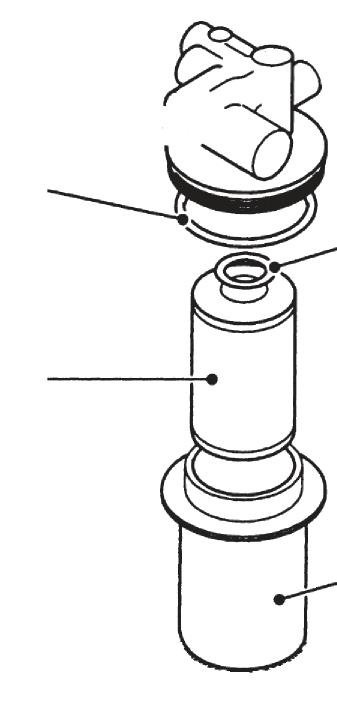
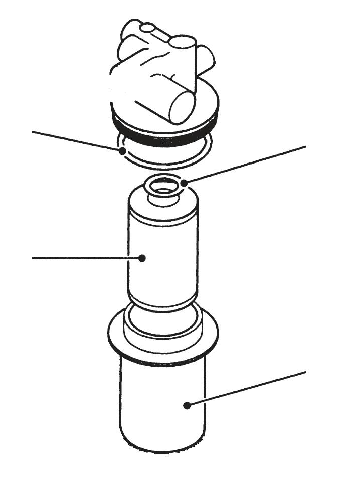

Check the filter bowl for accumulation of sediment or water and clean as required.
To replace the fuel filter element or clean sediment, remove the nut, sediment bowl (2) and O-ring (3). Sediment bowl can be cleaned at this time. Pull downward on the filter element (4) and discard. Examine the small O-ring (5) in the filter head and replace as necessary. Install new element, pushing upward until seated. Install sediment bowl O-ring and nut. Tighten the nut and wipe up spilled fuel.
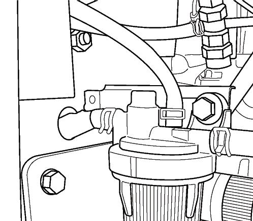
Air-bleeding Procedure
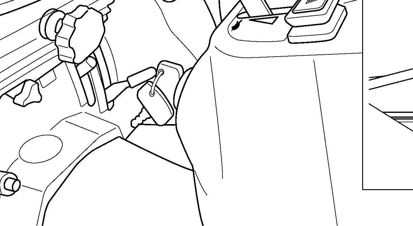
FIG. 108: Normally, further air-bleeding is not required due to automatic air-bleeding system operating when main switch in instrument panel is ON position.
When once the servicing such as emptying the fuel tank, be sure to air bleeding. To activate the airbleeding system, turn the main switch to ON position for several minutes. Start the engine and check the fuel system for fuel tank.
CAUTION: Fuel emitted from loosened injection lines is under high pressure. Keep hands and face away when the engine is cranked. Clean all spilled fuel following air-bleeding procedure.
NOTE: If engine will not start after several attempts, refer to the Troubleshooting Section.
Fuel Tank Filler Cap
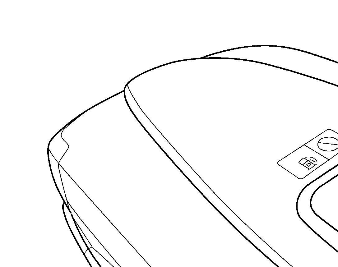
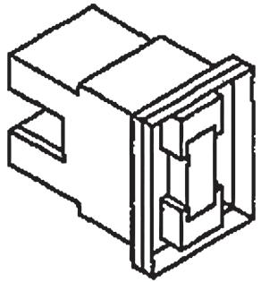
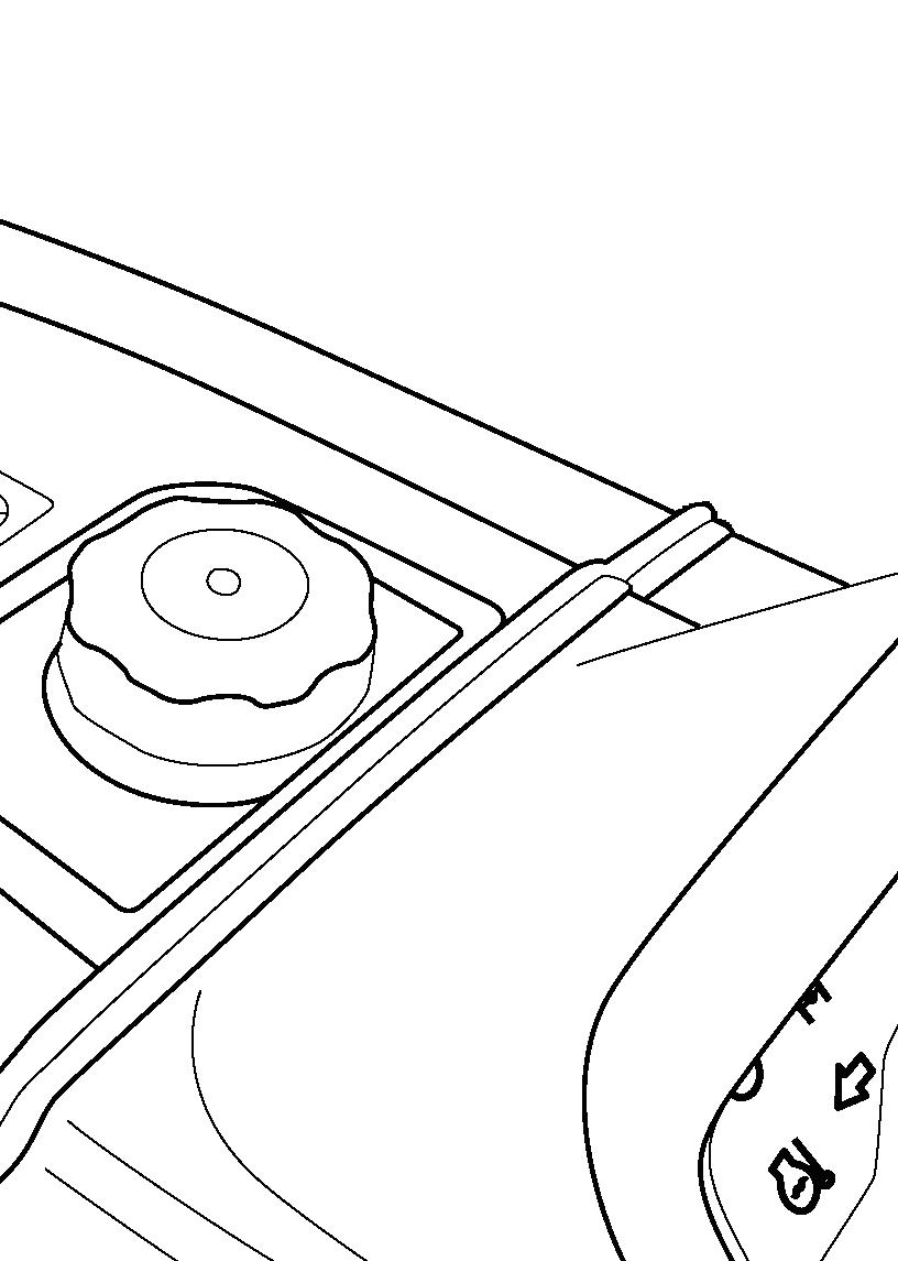
FIG. 109: When fuel tank filler cap (1) is removed, a hissing or popping noise may be noticed. This is due to cap design and is a normal condition. Do not alter cap or use unapproved replacement as fuel leakage may occur in event of tractor upset.
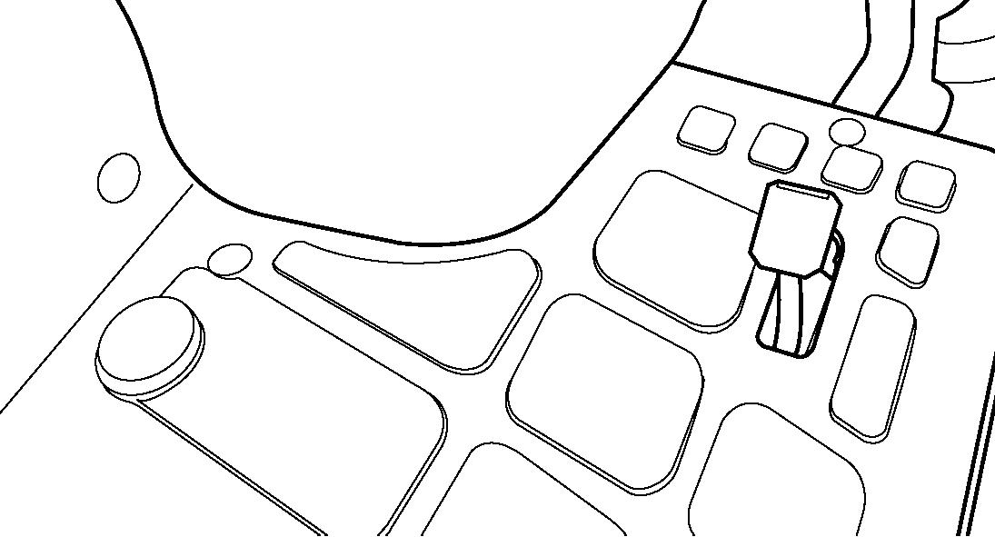
Throttle Lever
FIG. 110: The throttle lever (1) should remain in the position selected by the operator. Through normal use, friction against the lever may decrease, causing the lever to move out of the selected position. Turn the adjusting nut (2) as required to retain the throttle lever in the position selected.
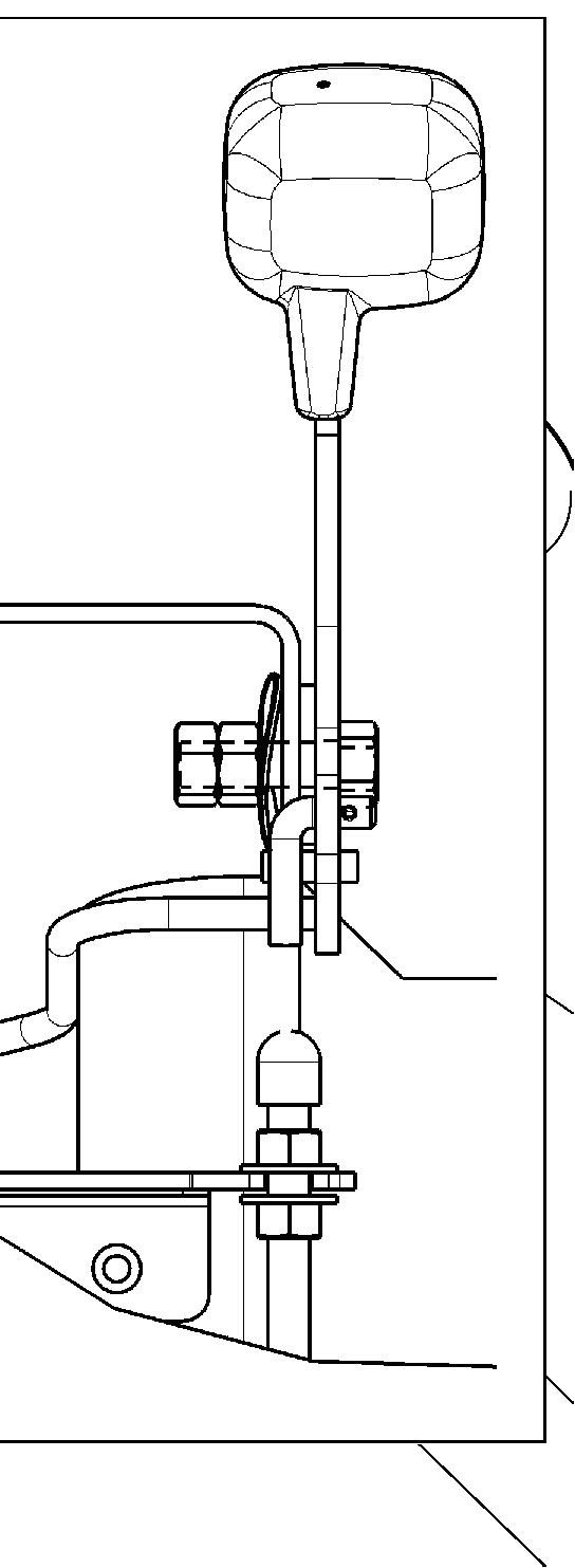
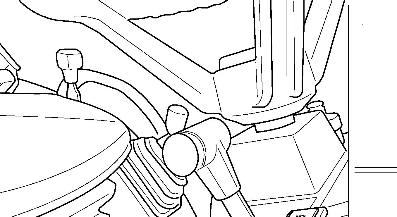
NOTE: Throttle lever friction adjustment nut is reached by removing the steering column cover and instrument panel.
Electrical System
Battery
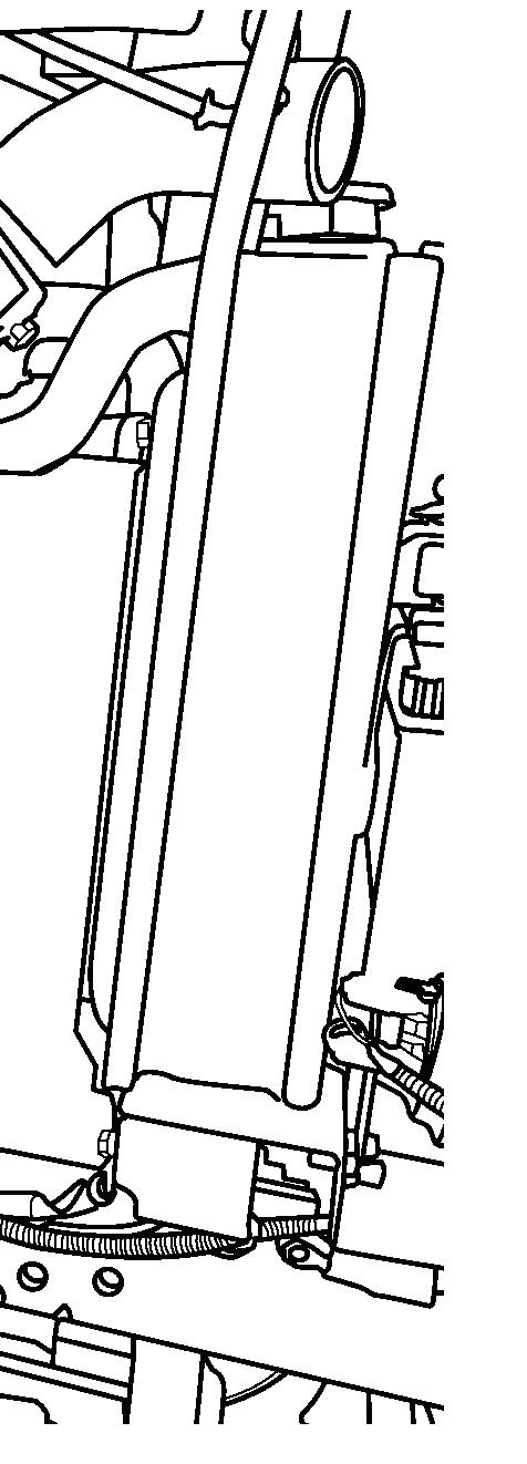
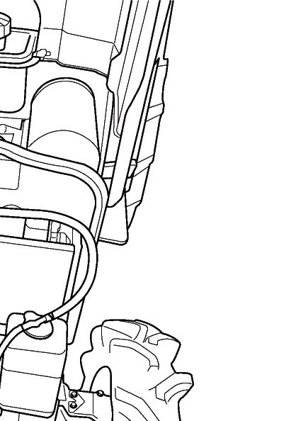
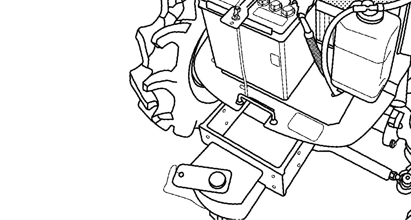
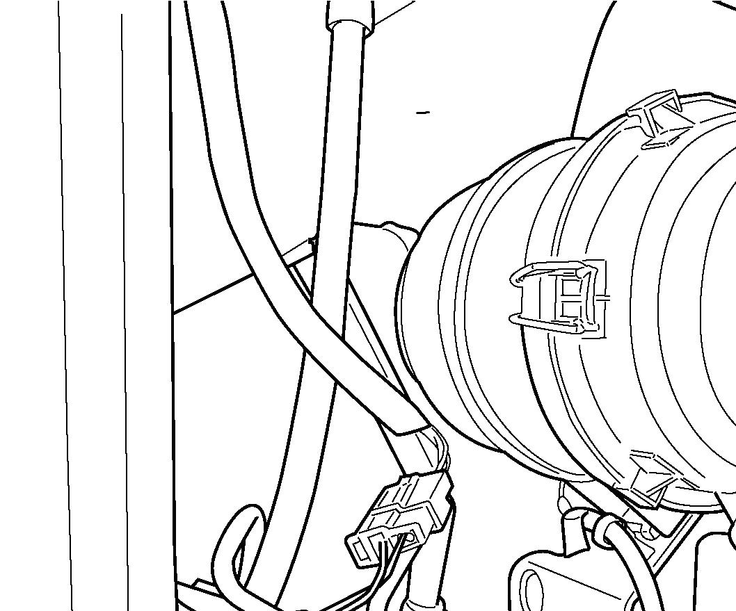
FIG. 111: Battery (1) is located under engine hood in front of radiator.

When battery is removed, electrolyte inspection or cable cleaning is necessary.
Keep top of battery clean and ensure cable connections are clean and tight. Debris on battery can cause discharge of battery and possible source of fire.
CAUTION: Batteries produce explosive hydrogen gas when charged. Keep all sparks and open flame away from battery.
When necessary to disconnect battery cables, always disconnect the grounded (-) cable first to prevent short circuits.
Batteries contain sulfuric acid electrolyte (fluid). Wear eye and face protection. If electrolyte comes in contact with skin or clothes, wash immediately. Contact a doctor if electrolyte is ingested or gets in eyes.
When the battery performance is weak, remove the battery and charge the battery, and follow instruction for the battery charger.
Repeated battery charging may be due to a defect in tractor charging system and / or a defective battery.
WARNING:
Never disassemble battery. Batteries contains sulfuric acid electrolyte (fluid). Keep away from sparks or flames, which could cause explosion.
When charging battery from an external source, Set charging voltage below 16V. Set charging ampere below 1/10 of the battery capacity. Prevent overcharge. Battery temperature must not exceed 113°F (45°C).
When connecting and disconnecting battery cables, turn off power of battery charger. If you have any question about battery, consult your dealer.
IMPORTANT: Do not quick-charge the battery, or it may damage the battery and decrease its performance.

IMPORTANT: Charge the battery before the first use of this tractor.
IMPORTANT: When storing tractor for long period without operation, self discharge of battery will happen (especially in winter). If the tractor is stored for more than 1 month, the battery minus terminal should be disconnected.
When operating for the first time or after long term storage, check if the battery charge level is enough. (If measurement of battery voltage is available, check if the voltage is more than 12.5 V.) When the tractor is stored more than 2 months in summer or 3 months in winter, charge the battery.
NOTE: When handling the battery, never close or cover vent of battery.
FIG. 112: The battery is required the electrolyte inspection. Make sure that the electrolyte level is between upper limit (A) and lower limit (B). When the level is below lower limit, raise the level with distilled water
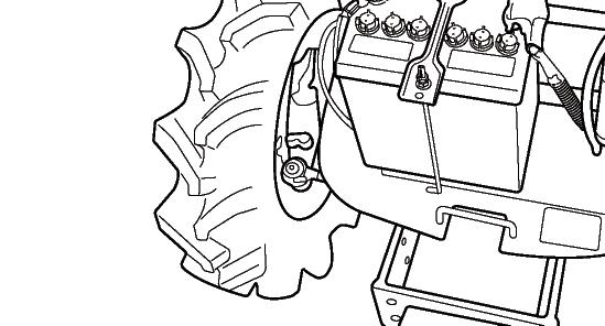
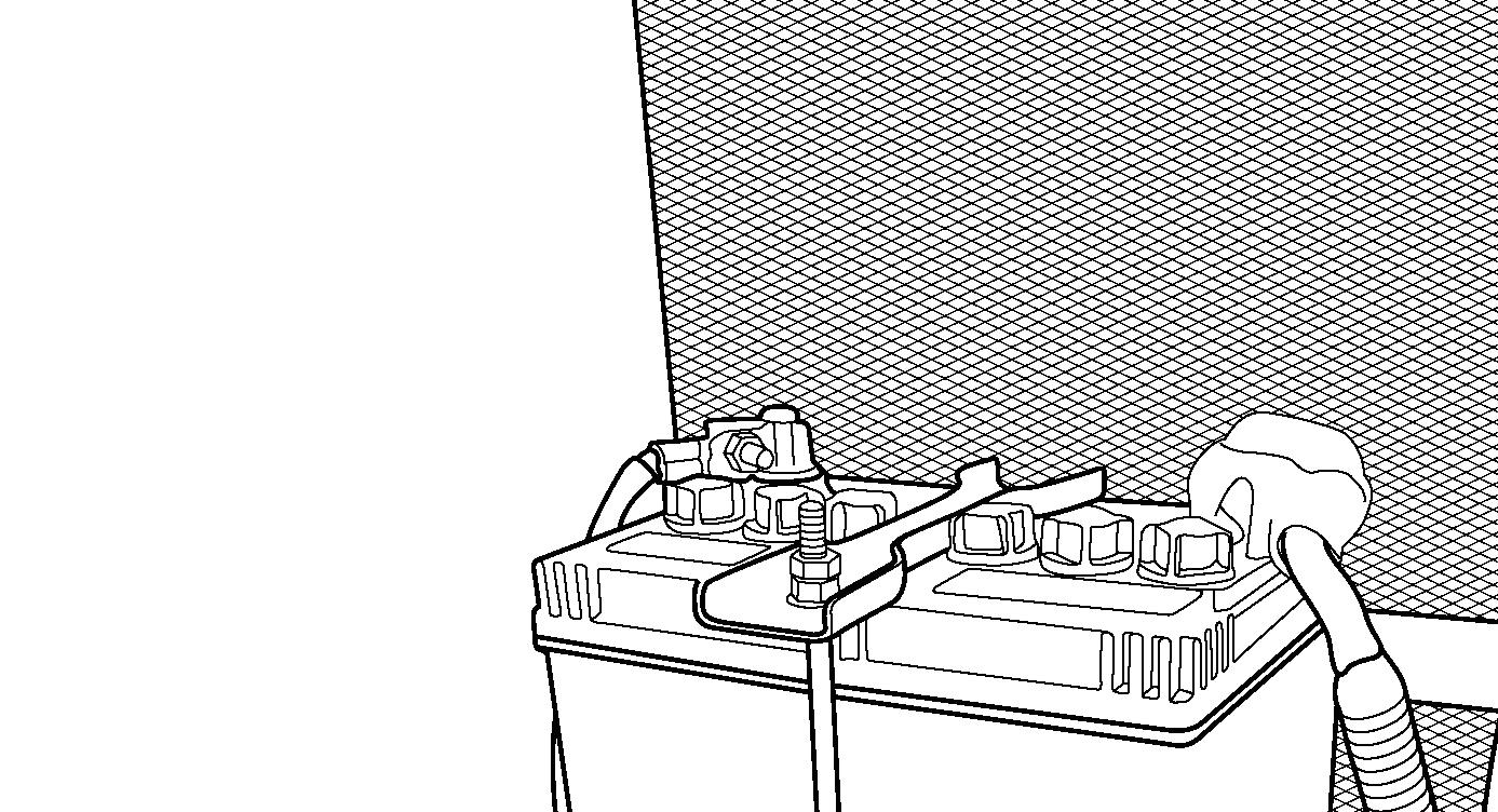
FIG. 113: To replace the battery, disconnect negative (-) cable (1) first and then remove positive (+) cable, 2. Loosen and remove battery securing clamp and carefully
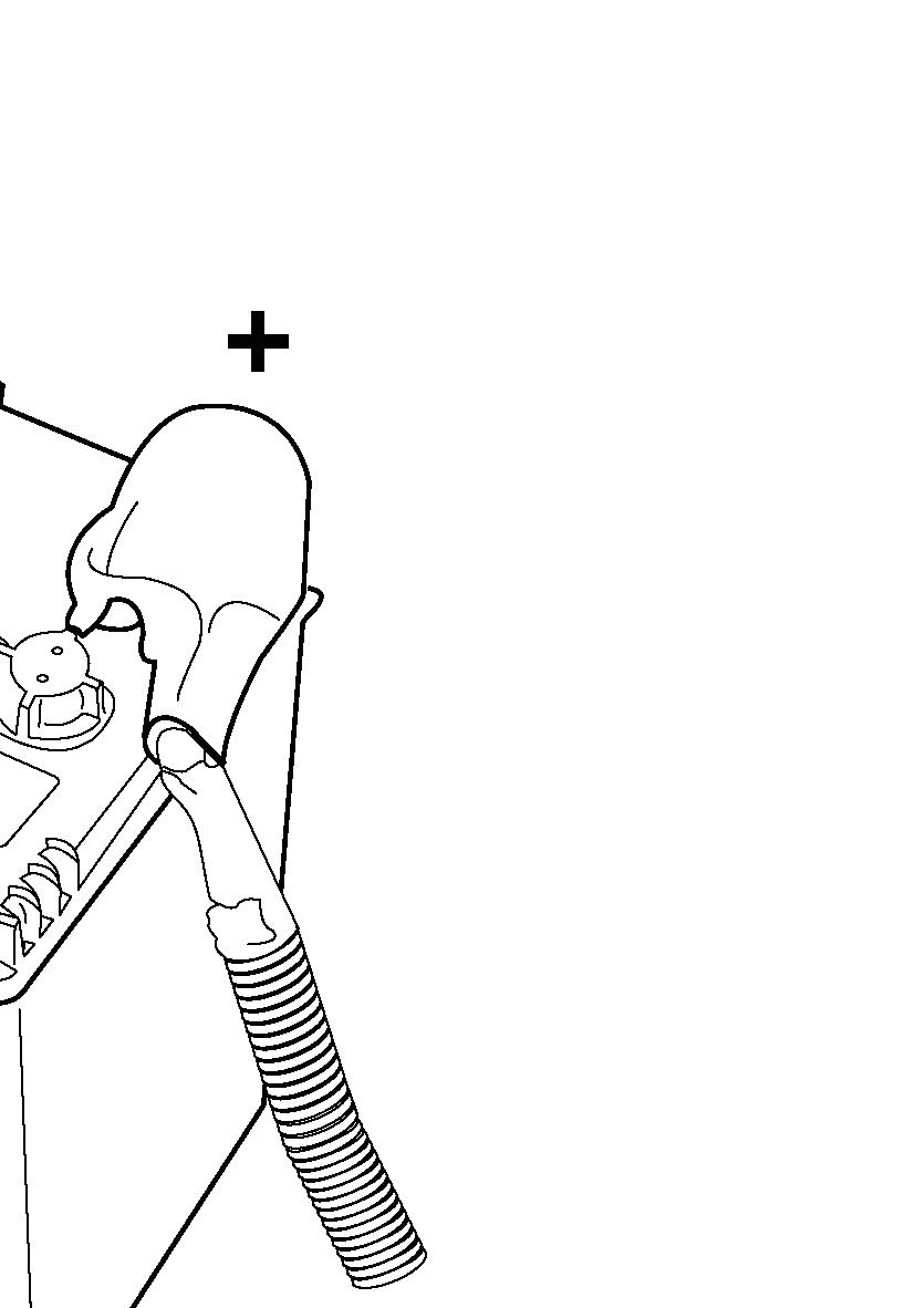
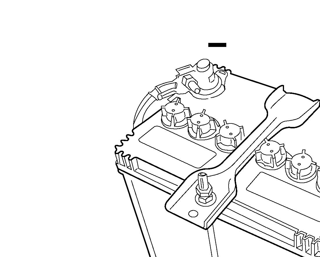
When installing battery, cable (2), connected to starter solenoid should be connected to positive (+) battery terminal first then cable (1) grounded to tractor frame can be connected to negative (-) battery terminal.
NOTE: Make sure that replacement battery is same size and equal capacity. (44B19R)
IMPORTANT: Do not reverse battery cable connections as severe electrical system damage will result.
Starting Switches
This tractor is equipped with a neutral-start system consisting of neutral switches and a relay. To start tractor, ALL the following is required:
• Clutch pedal depressed.
• Range Gearshift Lever in neutral position.
• Rear PTO Lever in neutral position.
• Operator seated on the seat.
WARNING: DO NOT bypass or modify the neutral switch. If the neutral start system does not operate properly, consult your dealer immediately.
NOTE: A seat safety switch is incorporated into system. The engine stops when operator leaves the seat in case that PTO switch is not “OFF” or forward / reverse lever is not in neutral position.
Wiring / Fuse Arrangement
CAUTION: Keep all wiring connections clean and tight. Make sure wiring is correctly secured to prevent damage.
CAUTION: DO NOT alter wiring by adding “home-made” extensions or replacements. Doing so can eliminate fuse protection and / or eliminate safety features of the system.
CAUTION: The tractor is equipped with negative (-) ground system. Tractor metal parts provide many electrical connections. For this reason, all positive (+) circuits must be insulated to prevent “grounding” or short circuits and prevent possible fire.
CAUTION: DO NOT replace any fuse with a fuse of higher amperage rating. DO NOT use wire (or foil) to by-pass fuse protection. Fire can result.
If fuses blow repeatedly, examine the electrical system for “earthed” or “shorted” circuits.
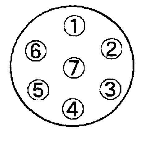
(A)
Ref.AmpFunction
110AHorn, Parking Warning buzzer
215AHeadlamp
315AHazard Warning Lamp
410AStop Lamp
510A Engine Stop Solenoid, Starter relay
615APower Supply (ACC)
715AACC / Turn Signal Lamp,
810AACC / Meter Rely & Safety Relay
915A ACC / Power supply for beacon lamp
105AGlow Lamp
(B) Slow Blow Fuses - Located near the rear lefthand side of engine.
In-line fuses protect relevant circuit by melting when sustained heavy electrical load or short circuit is encountered.
IMPORTANT: Slow blow fuses are of amperage capacity for the circuit in which they are located. Use only authorized parts for replacements.
Ref.AmpFunction
B-140AAlternator Circuit (Green)
B-240AMain Switch (Green)
(C)
Ref.DINFunction
LLeft-hand side direction indicator lamp
5231Ground
RRight-hand side direction indicator lamp
58RRight-hand side position lamp
54q Stop lamps for rear combination lamps
58LLeft-hand side position lamp
(D)
CLUTCH FREE-PLAY ADJUSTMENT
FIGS. 115 & 116: Check clutch pedal free-play regularly and adjust as necessary. Correct clutch pedal free-play (A) is 20 to 30 mm (7 / 8 to 1-1 / 8”) when measured at the end of the pedal (1) as shown.
NOTE: Through use, clutch free-play will be reduced.
IMPORTANT: Correct free-play must be maintained to reduce wear on the clutch and release bearing, and allow complete disengagement when the pedal is depressed.
To adjust clutch pedal free-play, locate the linkage under the left foot step, and loosen the lock nut (2). Adjust the turnbuckle (3) on the linkage until free-play is correct. Lengthening the linkage will increase freeplay, shortening the linkage will reduce free-play.

Secure by retightening the lock nuts.
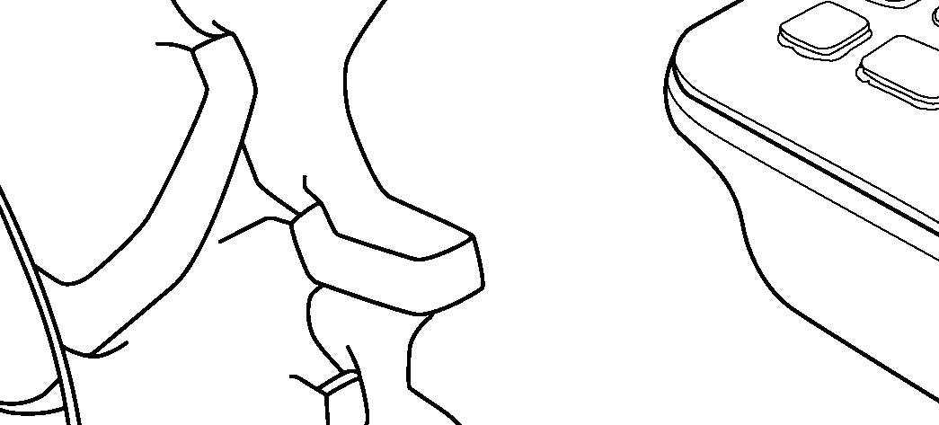
BRAKE FREE-PLAY ADJUSTMENT

FIG. 117: Unlatch the pedals (1) and check free-play of each brake pedal. Correct free-play (A) of each individual brake pedal is 20 to 30 mm (7 / 8 to 1-1 / 8”).
NOTE: Through use, free-play will increase and brake balance will be affected. Adjust and balance brakes before free-play is excessive.
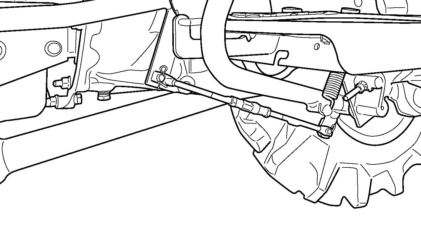
FIG. 118: Loosen the lock nut (1). Adjust the rod using nut (2) so free-play is correct for respective brake pedal.
Repeat procedure for other brake so free-play in pedals is equal. Secure lock nuts against clevis.
When adjustment is complete, latch the pedals together and operate the tractor at low speed. Depress the pedals. If the tractor has tendency to “pull” to left to right side, readjust the free-play evenly between left and right side.
Make sure the lock nuts are secured when brake adjustment is complete.
FIG. 119: To adjust the parking brakes, loosen righthand lock nuts (1 and 2). Adjust the rod using turn buckle (3).
When above adjustment is completed, check operation of parking brakes. Depress the pedals fully and apply parking brakes. It should have brakes locked with the lever approximately in center of travel. Make sure the lock nuts are secured when brake adjustment is completed.
CAUTION: Brakes must be adjusted evenly to permit equal braking action at both rear wheels when brake pedals are latched together.
WHEELS & TIRES
Check wheels and tires periodically for correct inflation pressures, tight wheel bolts, and any physical damage that may be a detriment to tractor operation and operator safety. Correct condition prior to tractor operation.
Tire Inflation Pressures
TABLE 11: Maintaining correct tire pressure will help insure tire life. Never exceed the maximum inflation pressure specified on the tire. If tires have deep scratches, cuts or punctures, the respective tire should be repaired or replaced by qualified personnel as soon as possible.
IMPORTANT: If necessary to replace any tire, ensure original tire size is used. This is particularly true to ensure correct amount of front axle overspeed (or “lead”) is maintained.
TABLE
Wheel Bolt Torque
Periodically check all wheel bolt torques. Correct bolt torques:
Front Wheel Bolts.......102 Nm (75 ft-lbs)
Rear Wheel Bolts........102 Nm (75 ft-lbs)
CAUTION: Correct wheel bolt torque must be maintained. Installation of front or midmounted implements (ex: loaders, mowers) impose increased loads and require frequent checking of wheel bolts.
TM3185F3
Front Wheel Spacing
FIG. 120: Front 4WD Wheels - Agri tires can be reversed. Turf tires cannot be reversed.
TABLE 12: Front wheel setting
Tire TypeTire Size Setting (mm) ABC
Front Agri 5 x 12 4PR 755925-
Turf 20 x 8.00 -10 4PR --860
Agri 5.00 x 12 4PR 755 920-
Rear Wheel Spacing
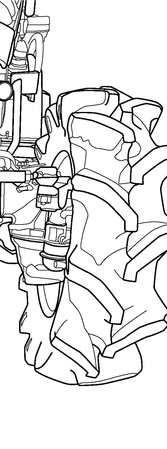
FIG. 121: Rear Wheels - Agri tires can be reversed. Turf tires cannot be reversed.
TABLE 13: Rear wheel setting
Tire TypeTire Size Setting (mm) ABC
Agri 8 x 16 4PR 720895-
Rear
Turf 215 / 80 D -15 4PR 805/ 815
Agri 9.5 x 16 4PR 755865-
CAUTION: Rear wheels are heavy. Use care when moving them. Make sure the tractor is blocked securely. Tighten all wheel bolts securely and recheck after short period of operation.
Steering Free-Play
FIG. 122: Check steering for excessive looseness, as indicated by steering wheel free-play. Maximum freeplay is approximately 30 to 60 mm (1-1 / 4 to 2-3 / 8”) when measured at the outside of steering wheel rim as shown at “X”.
Excessive free-play can be caused by:
• Loose or worn ball joints
• Worn or damaged steering column shaft / universal joints
• Worn or damaged power steering unit (if equipped)
CAUTION: Excessive steering free-play must be corrected before use. Contact your ISEKI dealer.
Front Wheel Alignment
FIG. 123: Correct “toe-in” dimensions of front wheels (A minus B) are as follows:
4WD..........................................2-6 mm (0.08 to 0.24”)
To adjust, loosen lock nuts (1) and adjust tie rod length by turning turnbuckle (2). Adjust each side evenly. Ball joints must move freely after lock nuts are tightened.
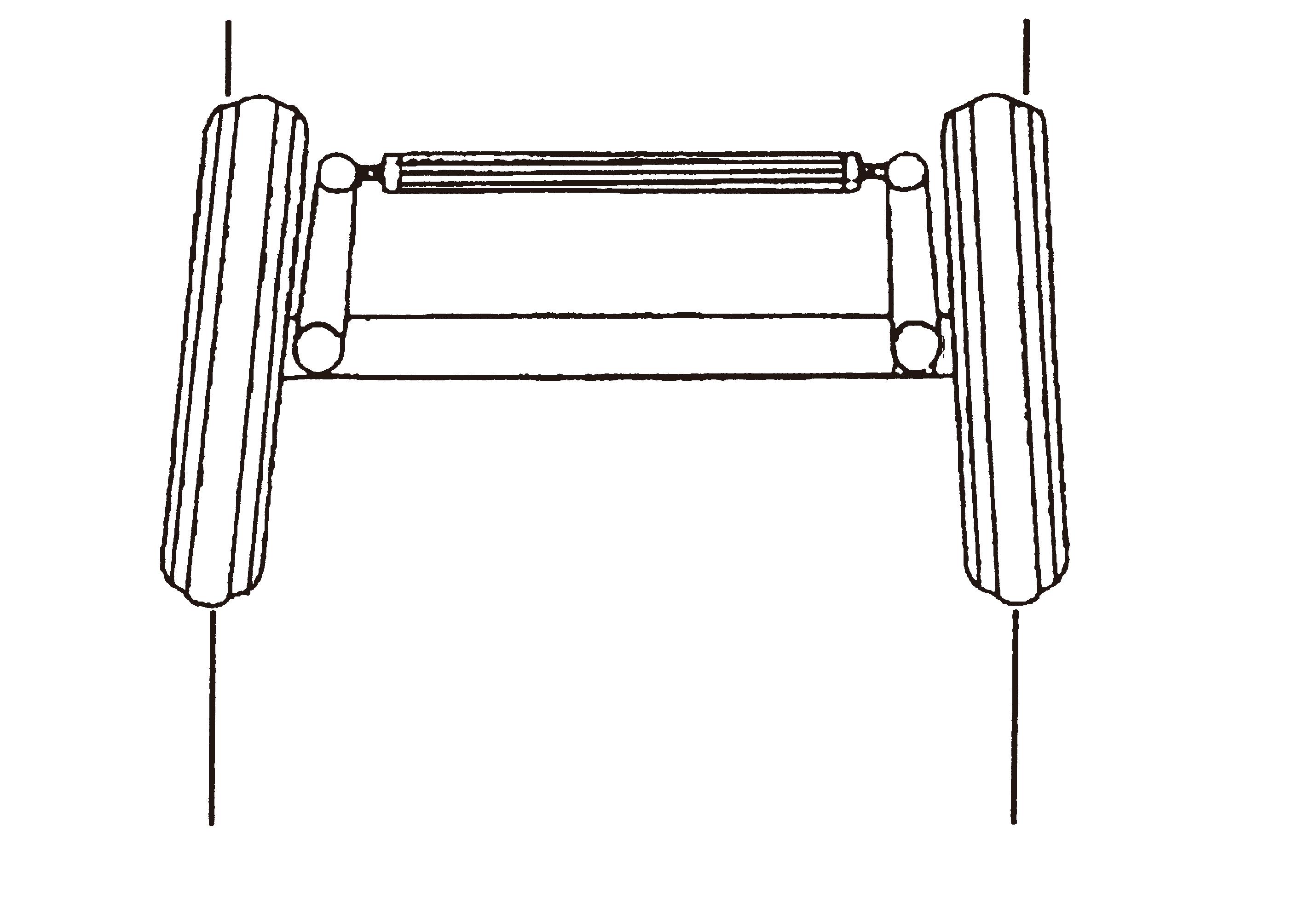
NOTE: Measure toe-in from tire center to tire center at a point halfway up on face of each tire.
Tie rod
FIG. 124: Make sure that nuts (1) on both tie rod ends (2) are not loosened. If loose, tighten the nuts.
When tie rod is defective, consult your dealer.
WARNING: Take notice that handling may be caught of cause the extreme shaking by the loosened nut. Otherwise it may result in the unexpected accident.
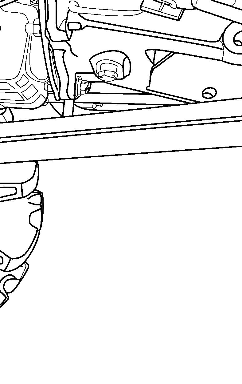
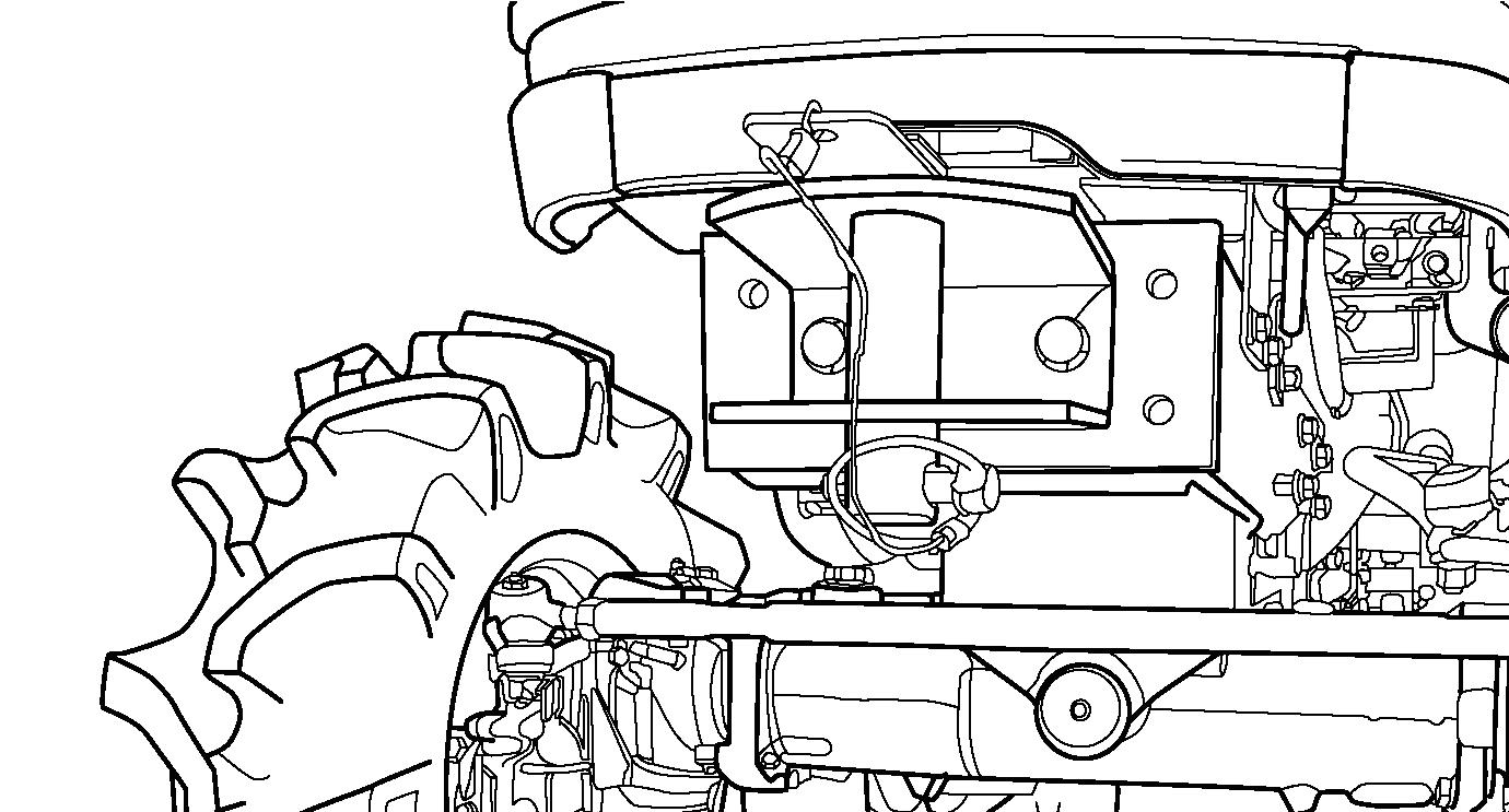
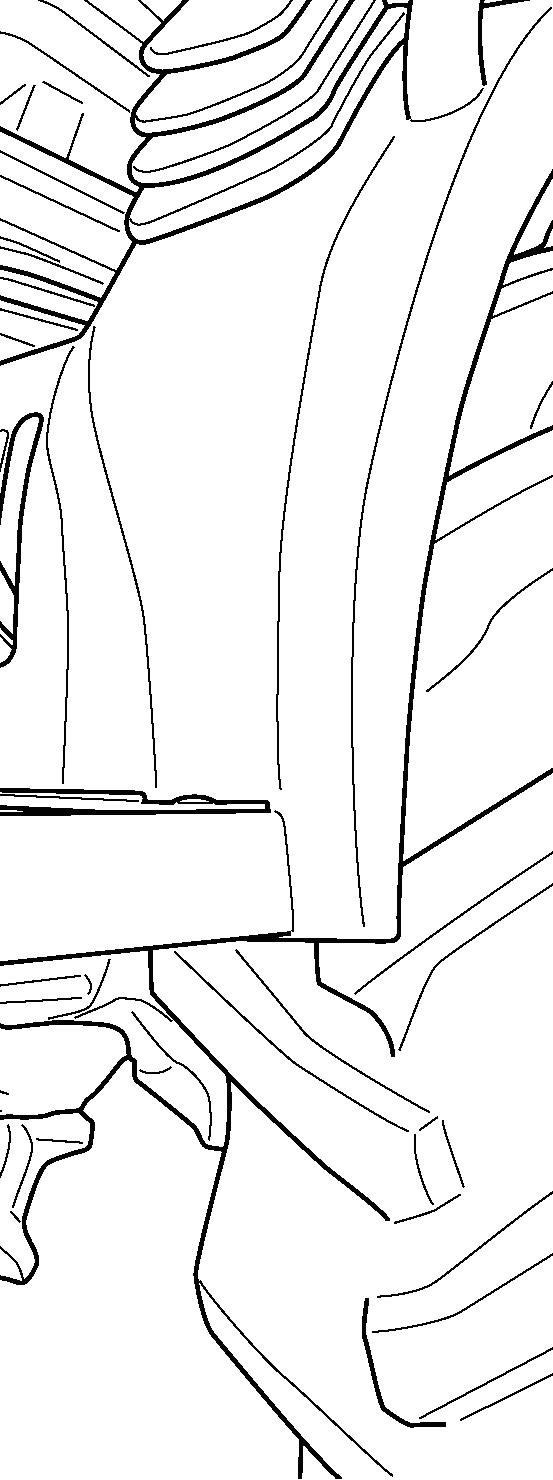
Clutch Housing Plug
FIG. 125: Pipe plug (1) should be removed from the bottom of the clutch housing once a year or when clutch slipping is apparent. Any oil leakage from the engine rear crankshaft seal and / or transmission input shaft will be indicated by oil draining through the hole. Contact your ISEKI dealer if oil leakage is evident.
Torque Chart
TABLE 14: All fasteners should be tightened in accordance with the torque chart unless a specific torque value is called out in relevant maintenance information.

Storage
FIGS. 126 & 127: If the tractor is to be stored for extended periods such as off-season non-use, certain measures should be taken for its preservation during such periods. These measures will vary according to geographical area and storage season.
1. Replace engine oil and filter. Operate at low idle 5 minutes to lubricate parts.
2. Lubricate all grease fittings and lightly oil control linkage pivots.
3. Detach implements.
4. Store the tractor in an enclosed area, if possible, for protection from weather.
5. Block up the tractor to remove weight from tires and to protect tires from oily or damp floor.
6. Raise and lock the 3-point lift linkage in up position by turning the lowering rate control handle (1) fully clockwise.
7. Fill the fuel tank to prevent condensation from forming on inside of the tank.
8. Remove the battery and store in cool dry place. Maintain charge during storage period.
9. If the tractor is stored during cold weather season insure that anti-freeze is adequate. Alternatively, the radiator and engine block may be drained.
10. Check with your diesel fuel supplier on the availability of a diesel fuel additive to place in the fuel system during storage period.
11. If the tractor cannot be placed in an enclosed area place it under some sort of cover and cover exhaust pipe to prevent entrance of rain or snow.
12. To prevent clutch seizure during long periods of tractor storage, depress clutch pedal and secure in the disengaged position with the hook (2).
13. Touch-up scratches with paint.
At the end of storage period: Perform appropriate lubrication and maintenance before placing the tractor back in service. Refer to “Lubrication and Maintenance” section.
• Conduct full pre-start inspection. Make sure all controls operate correctly.
• Allow the engine to idle approximately 30 minutes. Check for leaks and repair as required.
Washing Of The Machine
Wash the machine periodically. Carefully wash the area where mud spatters easily such as fender inner part.
CAUTION: If you use high pressure washer, be sure to use in accordance with operator’s manual and safety label of washer. In case of irregular using, it may cause personal injury and damage to the machine.
CAUTION: Set the nozzle of hose ‘spread’ and keep the distance more than 60 cm in order to avoid damaging to the machine. Especially, be care for not to hit the water to electrical parts and label.
FIG. 128: Unsuitable washing may cause the following accidents;
1.Fire as a result of short circuit or the damage to the electrical parts.
2.Oil leakage as a result of the damage to the hydraulic hose.
3.Damage to the machine.
(1) Label is come off.
(2) Accident occurs by the damaged electrical parts, engine, radiator, and interior.
(3) Rubber parts (tire, seal) and resin parts are damaged.
(4) Paint is come off.
Keep