27 minute read
MAJOR COMPONENTS


CAUTION: Become familiar with all operating controls prior to operating tractor. Read this operator’s manual in its entirety before starting.
Instrument Panel
FIG. 35: Gauges, control switches and indicators are located in instrument panel. Items are as follows:
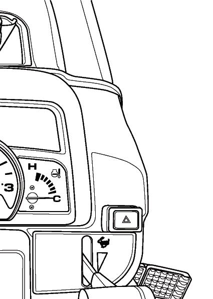
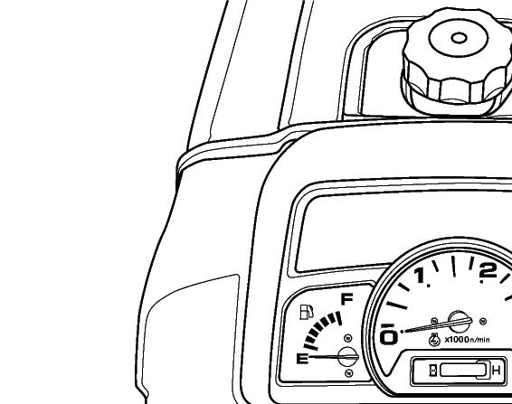
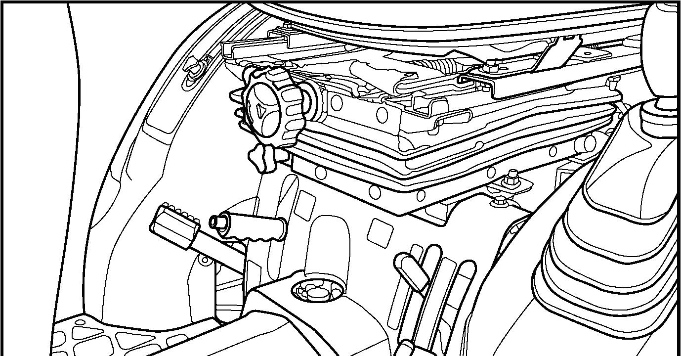
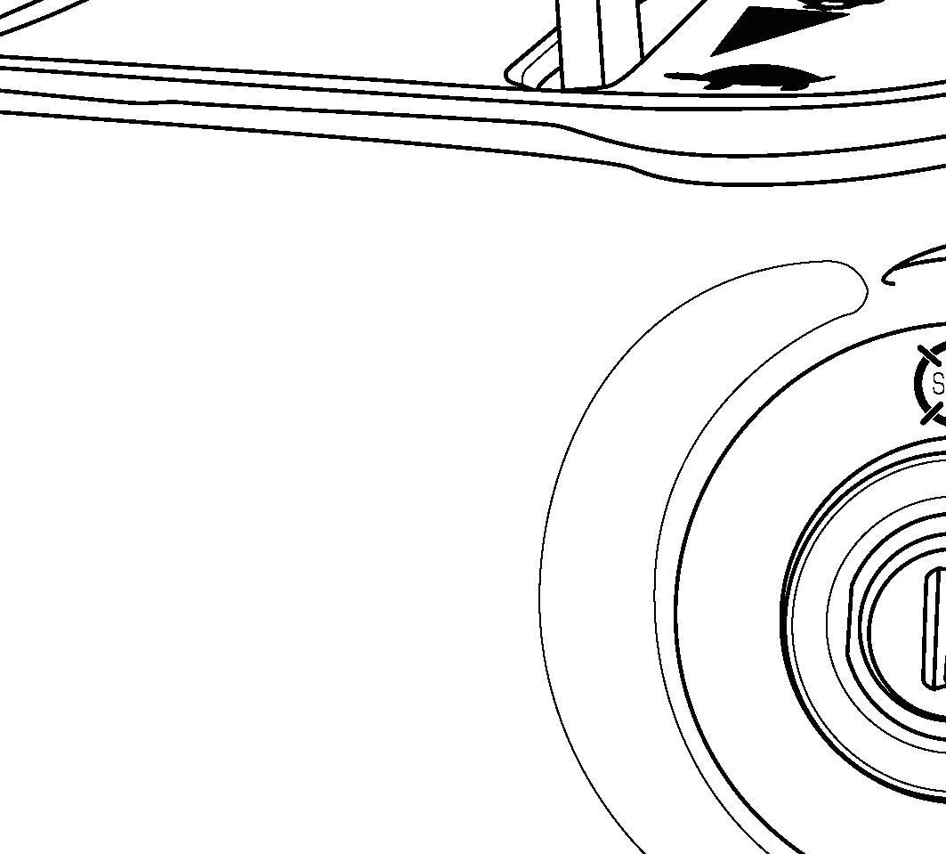
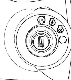
FIG. 36: Main Switch, 1, has the 4 following positions:

OFF....... Tractor engine and all electrical circuits off.(except for headlamp, position lamp, rear registration plate lamp and hazard warning lamp) Turning main switch to OFF position will stop engine. Key can be removed.
ON........ Power supplied to all circuits. Normal operating position.
GLOW... Energizes glow plugs to preheat the combustion chambers and assist starting.
START...Starter activated. This position is spring located to “ON” position.
NOTE: The main switch must be turned to “ON” position before any circuits will operate. The PTO lever must be off and the clutch pedal depressed before the engine can be started.
NOTE: When the main switch is selected to “GLOW” position, the engine combustion chambers will be preheated and allow a cold engine to be started after several seconds.
Indicator Light Array
FIG. 37: Indicator light array contains several indicator lamps to monitor certain functions. The lamps are as follows:
• 1. Battery Charge Lamp - Illuminates when the main switch is turned to the ON position and will go out after the engine starts, to indicate the battery is being charged.
• 2. Engine Oil Pressure Warning Lamp - Illuminates if engine oil pressure is low. If the lamp comes on while the engine is running, stop the engine immediately and find the cause.

• 3. Parking Brake Lamp - Illuminates when parking brake is applied.
• 4. Trailer Indicator / Hazard Warning Lamp - Illuminates when the trailer is attached with connecting 7 pins socket, or the hazard warning lamp switch is ON position.
• 5. 4WD Indicator Lamp - Illuminates when 4WD is engaged by pushing down the 4WD shift lever.
• 6. Glow Lamp - Illuminates when the main switch is turned to the GLOW position. The lamp illuminates until the glow is ready.
• 7. Main (high) Beam Lamp - Illuminates when main (high) beam headlamp is selected by the direction indicator lamp control lever.
• 8. Left-hand Side Direction Indicator Lamp - Illuminates when the direction indicator lamp control is turned to the left-hand side direction indicator lamp position (Upper position).
• 9. Right-hand Side Direction Indicator Lamp - Illuminates when the direction indicator lamp control is turned to the right-hand side direction indicator lamp position (Lower position).
Tm3185f3
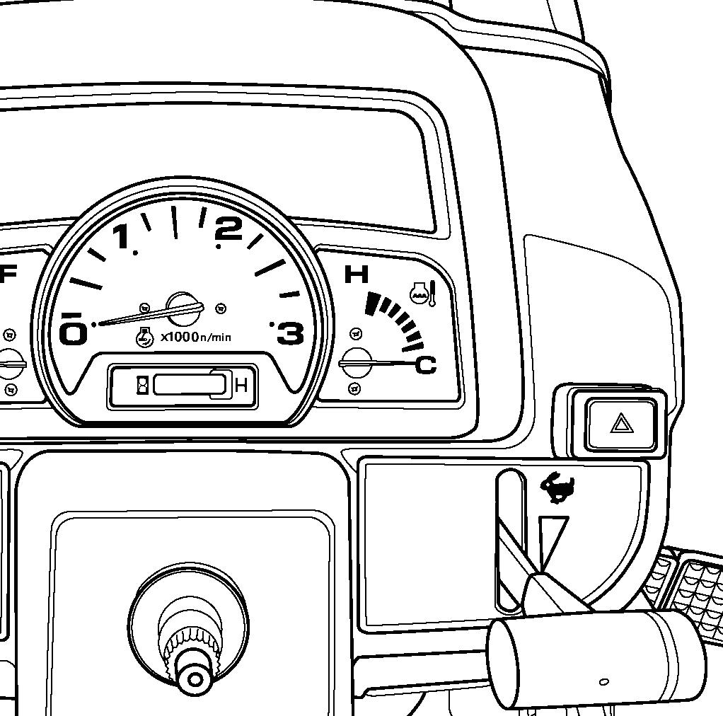
Tachometer & Engine Hourmeter
FIG. 38: Tachometer (1) indicates engine speed in crankshaft revolutions per minutes (min-1).
Engine Hourmeter in center of gauge (2) indicates used hour of engine and tractor assist in maintenance intervals. The extreme right digit indicates 1 / 10 hour increments.
Coolant Temperature Gauge
FIG. 39: Coolant temperature gauge (1) indicates engine coolant temperature.
• (A) C - Shows too cool of a temperature for severe work. Let the engine warm (needle in mid position) before applying a heavy load.
• (B) H - Indicates the engine is too warm (red area on gauge). Reduce engine speed to idle, allow to run at no load several minutes. Stop the engine and find the cause (refer to “Troubleshooting”).
CAUTION: DO NOT service hot engine. Allow to completely cool before servicing or removing radiator cap.
Fuel Gauge
FIG. 40: Fuel gauge (1) indicates the level of diesel fuel in fuel tank. When needle is the closer to “Full point” (2) the more fuel is in the fuel tank. So not let the fuel gauge reach the “Empty point” (3).
NOTE: The gauge can not indicate an accurate fuel level when the tractor is on a incline. It takes a little time to indicate an accurate level after the tractor recovers its horizontal position limit.
NOTE: Use only clean diesel fuel and clean area to prevent dirt / water into fuel tank when refilling. DO NOT run out of fuel as bleeding air from the system will be required. Keep fuel tank full to minimize condensation.
CAUTION: DO NOT refill fuel tank with engine running or in hot condition. Before refilling, stop the engine and wait until engine is cooled down. Do not smoke near fuel tank and clean up any spilt fuel.
Switches
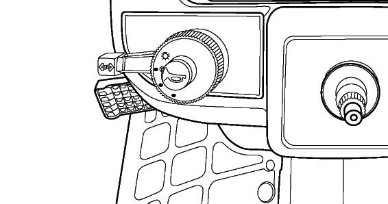
FIG. 41: Horn will sound when horn switch (1) is depressed.

Headlamp switch (2) is a rotary switch with (3) operating position.
• (A) OFF position - Fully counterclockwise. All lamps off.
• (B) 1st position - Position lamps and rear registration plate lamp
• (C) 2nd position - Headlamps, rear registration plate lamp and position lamps.
Operate direction indicator lamp control (3) in direction tractor is being turned. Left-hand side or right-hand side direction indicator lamps will operate as turn signal. Return switch to center position to cancel.
NOTE: Direction indicator lamps will not self-cancel. Turn the direction indicator lamp control to the center position after completing turn.
FIG. 42: Direction indicator lamps in the indicator light array (4) will operate with left-hand side and righthand side direction indicator lamps. This provides operator with easy indication of warning lamp selection.
FIG. 43: Press hazard warning lamp switch (5) to turn on hazard warning lamp. Both left-hand side and righthand side direction indicator lamps will operate at the same time.
CAUTION: Hazard warning lamp must be used any time tractor is driven on public roadway. Consult local agencies for other marking requirements.
Clutch Pedal
FIG. 44: Clutch pedal (1) disengages engine from transmission when fully depressed, to permit engine starting, selecting / changing gears and stopping tractor movement. PTO and 4-wheel drive selection also requires clutch disengagement. Slowly raising the pedal will engage clutch and resume power to transmission and PTO.
NOTE: Clutch pedal should be depressed quickly to prevent abnormal wear. Clutch pedal should be raised smoothly to prevent sudden movement. DO NOT “ride” clutch pedal with your foot.
IMPORTANT: Correct clutch pedal free-play adjustment is a must. Refer to “Maintenance” section.
BRAKE
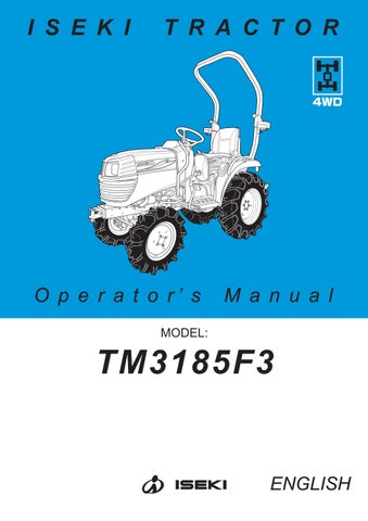
Brake Pedals
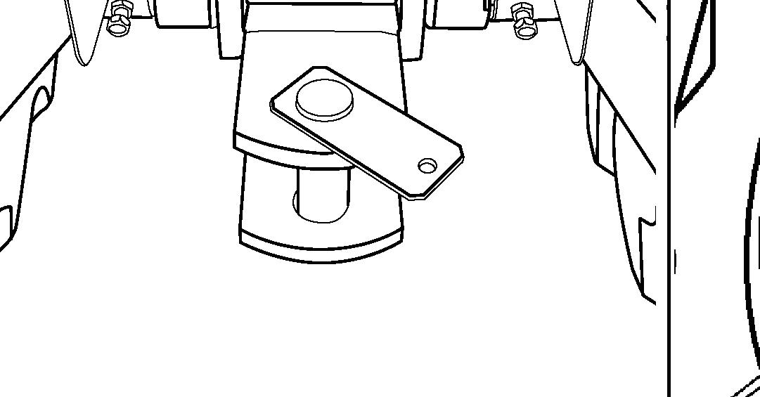
FIG. 45: Inner brake pedal (1) and outer brake pedal (2) independently control the respective left and right wheel brakes, to assist in turning. During traveling on road or operating at high speed, brake pedals must be latched together using interlocking plate (3).
CAUTION: Do not use individual wheel brakes and latch brake pedals together using interlocking plate when traveling on roads or operating at high speed. Make sure brakes are adjusted evenly.
Parking Brake Lever
WARNING: ALWAYS apply the parking brake before dismounting from the tractor.
FIG. 46 & 47: The parking brake acts on the tractor rear wheels. To engage parking brakes, pull upward on the parking lever (4) to lock brakes in applied position.
To disengage parking brakes, firmly depress both brake pedals to release the locking mechanism. Push in on release button (5) and lower the lever (4) to the released position.
IMPORTANT: Release the parking brake before driving the tractor to prevent increased wear.
NOTE: When the parking brake is applied, the parking brake lamp (6) will illuminate. (Refer to Fig.47).
NOTE: When the parking brake is not applied and engine is turned off, warning alarm and parking brake warning lamp (7) will let you know to apply the parking brake.
BREAK-IN PERIOD
Operation of tractor within the first 50 hours can be a major factor in determining the performance and life of the engine and tractor:
• The engine may be operated at full speed but excessive load should be avoided. If engine begins to “lug”, operate in a lower gear to maintain higher engine speed.
• Check coolant level and check engine, transmission and other oil levels frequently during break-in period. Watch for evidence of leakage of above fluids. Replenish levels as required and repair any leaks that may have formed.
• Tighten any nuts, bolts, or screws that may have loosened and tighten as necessary. This is especially true of wheel retaining bolts. All fasteners on this tractor are metric.
• Be observant of clutch pedal free-play adjustment and brake adjustment. And readjust as required. Lining materials used on clutch and brake discs “bed in” in the first few hours of operation and may need for early and frequent readjustment.
• Keep clean around fuel filler area and use correct grade fuel free from contamination.
• Initial engine oil and oil filter change is after first 50 hours of operation. Subsequent change interval is every 200 hours for engine oil and every 400 hours for engine oil filter.
CAUTION: Proper maintenance practices cannot be over-emphasized. They are required for safe operation. Consult “Lubrication and Maintenance” section for full details.
Starting
Pre-Start Inspection
Prior to daily start-up of tractor, a few basic procedures should be followed to ensure tractor is in operating order to insure life and dependability:
• Make sure all safety shields are in place and secured properly.
• Make sure operator is instructed on correct and safe operation of tractor and related attachments or implements.
• Check coolant, engine oil and transmission oil levels and replenish as necessary.
• Check fan belt tension every 100 hours and adjust as required.
• Make sure radiator, air intake screens and radiator screen are clear of debris to provide maximum engine cooling efficiently.
• Check operation of clutch, brake and throttle controls. All controls must be operated freely and adjusted correctly.
• Conduct a general inspection of tires, tire pressure and wheel bolt torque. Observe for external signs of leakage and correct before operating tractor. Check steering for excessive looseness.
• Check for adequate fuel supply. It is recommended fuel tank be filled following each day’s use to reduce condensation and provide full tank for next use.
• Check operation of lights and warning flashers. If tractor is to be transported on public road, ensure slow-moving vehicle emblem is in place.
NOTE: Requirements may be varied on locally for use of warning flashers and slow-moving vehicle emblem. Check local safety codes.
WARNING: Carefully read and understand the SAFETY section of this manual. Your life, and that of others, can be in danger during the starting of the tractor.
Always start and operate the engine in a well ventilated area.
If in an enclosed area, vent the exhaust to the outside. DO NOT modify or tamper with the exhaust system.
Normal Starting
CAUTION: Do not attempt to start the tractor unless seated in the operator’s seat. Do not allow anyone on the tractor except for the operator.
FIGS. 48, 49 & 50: To start the engine proceed as follows:
1.Latch the brake pedals (1) together by using interlocking plate and apply parking brake (2).
2.Place the main gearshift lever (3) and range gearshift lever (4) in the neural position.
3.Make sure the rear PTO lever (5) is in the neutral position.

4.Set the 3-point hitch position control lever (6) in the down position.
5.Fully depress the clutch pedal (7) to disengage the clutch.
CAUTION: Before starting the engine, the main gearshift lever and range gearshift lever must be in neutral and the PTO levers must be in neutral. The clutch pedal must be depressed to actuate safety switches and permit operation of the starter motor.
6.Set the throttle lever (8) at half to the fully open position.
7.Turn the main switch (9) to the “glow” position (10), for 5-10 seconds.
8.Turn the main switch (9), to the “start” position (11). Release the switch the moment engine starts.
IMPORTANT: Do not crank the engine for more than 10 seconds at a time. Allow the starter to cool at least 30 seconds before repeating procedure. Never turn the main switch to “start” with the engine running. Severe damage will result.
9.Once the engine runs smoothly, set engine speed to approximately 1 500 min-1 to allow the engine and hydraulic system to warm up for about 10 minutes. DO NOT SPEED UP AND LOAD IT ABRUPTLY. PARTICULARLY, OBSERVE THIS IN COLD SEASON OPERATION.
The battery charge indicator lamp (12) and engine oil pressure warning lamp (13) on the indicator light array must go out when the engine starts. If either of the lamps still stay illuminated, STOP THE ENGINE IMMEDIATELY and investigate source of problem.
NOTE: If the engine will not start and run after several attempts, refer to “Maintenance” section in this operator’s manual and bleeding air from the fuel system can be necessary.
Restarting Warm Engine
When restarting an engine that is still warm from previous use, the same procedure is used as with “normal starting” except step No. 7 may be omitted. Use of glow plugs is not necessary when starting a warm engine.
Cold Weather Starting
Procedure for starting an engine in cold ambient temperatures is identical to “Normal Starting” procedure except for the following:
• Longer use of glow plugs may be required. Instead of the normal 5-10 seconds, the main switch may need to be selected to “glow” for 10-20 seconds to adequately warm engine combustion chambers.
• Use of proper fuel for ambient temperature is recommended.
The European standard, EN590, contains climate dependant requirements and a range of options. The options can be applied differently in each country. There are five classes that are given to arctic climates and severe winter climates, 0, 1, 2, 3 and 4. Refer to EN590 for a detailed discretion of the physical properties of the fuel.
As for the diesel fuel ASTM D975 used in the U.S., at temperatures below -7°C (20°F) use of No.1-D diesel fuel is recommended due to possible “fuel gelling” characteristics of No.2-D fuel at cold ambient temperature.
• The central hydraulic fluid in addition to transmission and center housing lubrication, will require additional warm-up time due to cold (thicker) oil. Refer to “Warm-Up Period” below.
• Test all controls (steering, braking, etc.) prior to operating the tractor.
NOTE: Installation of accessory engine block heater is recommended in cold weather conditions. Consult your ISEKI dealer.
IMPORTANT: Never use any kind of starting fluid to start engine equipped with glow plugs. Otherwise, such starting fluid will contact hot glow plug and it will result severe engine damage.
In any case that a booster battery is required to start engine, ensure a booster battery is connected in parallel with the original battery. When using a booster battery and booster cables, always connect the both positive (+) terminals first. Then install booster cable on the booster battery negative (-) terminal. And connect it to ground of the tractor or negative (-) terminal of the original battery. Finally make sure the booster cable ends are away from tractor body or other battery to prevent short circuit or any sparks.
Warm-Up Period
After starting a cold engine, let the engine idle at slow speed to make sure all engine components are lubricated. In cold ambient temperatures, extended warmup will be required to also warm hydraulic fluid and lubricate driveline components.
TABLE 1: Suggested warm-up period
IMPORTANT: Improper warm-up can result in:
• Severe engine damage
• Hydraulic pump seizure
• Driveline bearing / gear damage
• Sluggish steering / braking
CAUTION: Make sure parking brake is securely applied and all controls are in neutral while warming unit. Do not leave unit unattended.
Operator Observations
Constant attention should be paid to the following points during operation:
• Engine oil pressure warning lamp will come on in case of low engine oil pressure. Stop engine immediately.
• Battery charge lamp will come on if the battery is not being charged properly. Stop the engine and investigate the cause.
• Coolant temperature gauge needle will indicate H (hot) in case of an overheated engine. Stop the engine, and allow it to cool and investigate the cause of overheating.
• Fuel gauge should not be allowed to reach E (empty) as running out of fuel may result with need to bleed air from the fuel system.
CAUTION: DO NOT attempted to service the tractor with the engine running or hot. Allow it to cool.
NOTE: Refer to “Trouble-Shooting” when defect is indicated, to assist locating problem.
Starting Circuit Operation
Tractor is equipped with a safety starting system to protect the operator. To permit tractor to be started (start motor to operate), ALL the following is required:
• Clutch pedal depressed.
• Range Gearshift Lever in neutral position.
• Rear PTO Lever in neutral position.
• Operator seated on the seat.
WARNING: Safety switch system is installed for your protection. DO NOT bypass or modify the safety start switch system. If the safety start switch system does not operate properly as detailed above, contact your dealer immediately and have the system repaired.
Periodically check that the starting circuit is functioning correctly. The procedure for check is as follows:
1. Check that there are no bystanders around the tractor in order to avoid the inadvertently start.
2. Depress clutch pedals. Attempt to start the tractor, and then the tractor should start.
If starting system is not working correctly it must be repaired immediately by your dealer.
When the clutch pedal is not depressed, the engine will automatically stop after the operator leaves the seat for more than 2 seconds. Do not leave the seat while operating the tractor.
Engine Speed Controls
CAUTION: Always select engine speed to ensure safe operation. Reduce speed prior to turning or reversing tractor.
IMPORTANT: DO NOT “race” or excessively load cold engine.
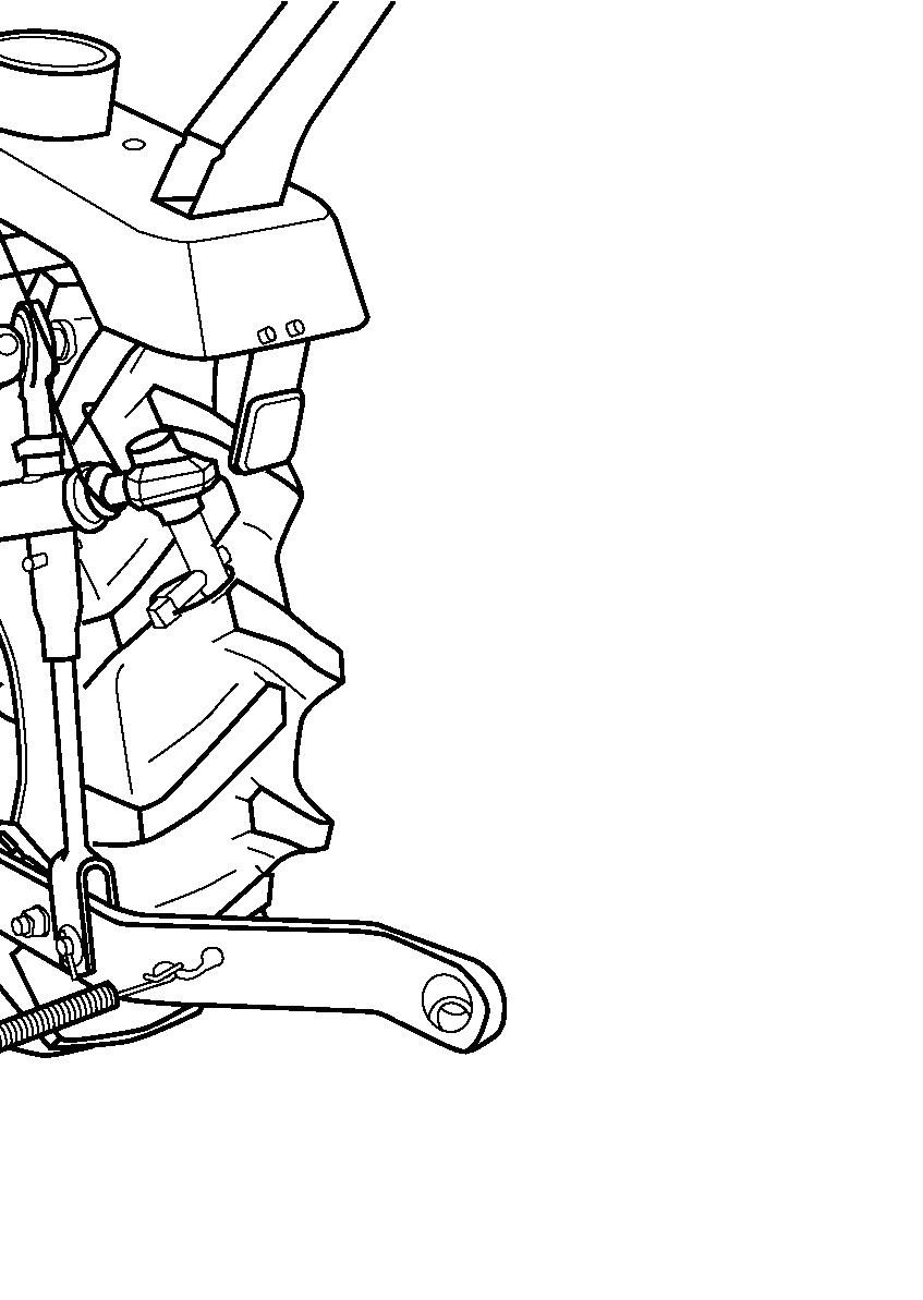
FIG. 51: Throttle lever (1) controls engine speed and will remain in position selected by the operator. With hand lever rearward, engine will idle. Engine speed increases as lever is pushed progressively forward.
Foot throttle pedal (2) will override setting of the throttle lever for increased engine speed. When the pedal is released, engine speed returns to the throttle lever setting.
CAUTION: When using the foot throttle pedal, the throttle lever must be in low idle speed position. This ensures maximum “engine braking” when the pedal is released.
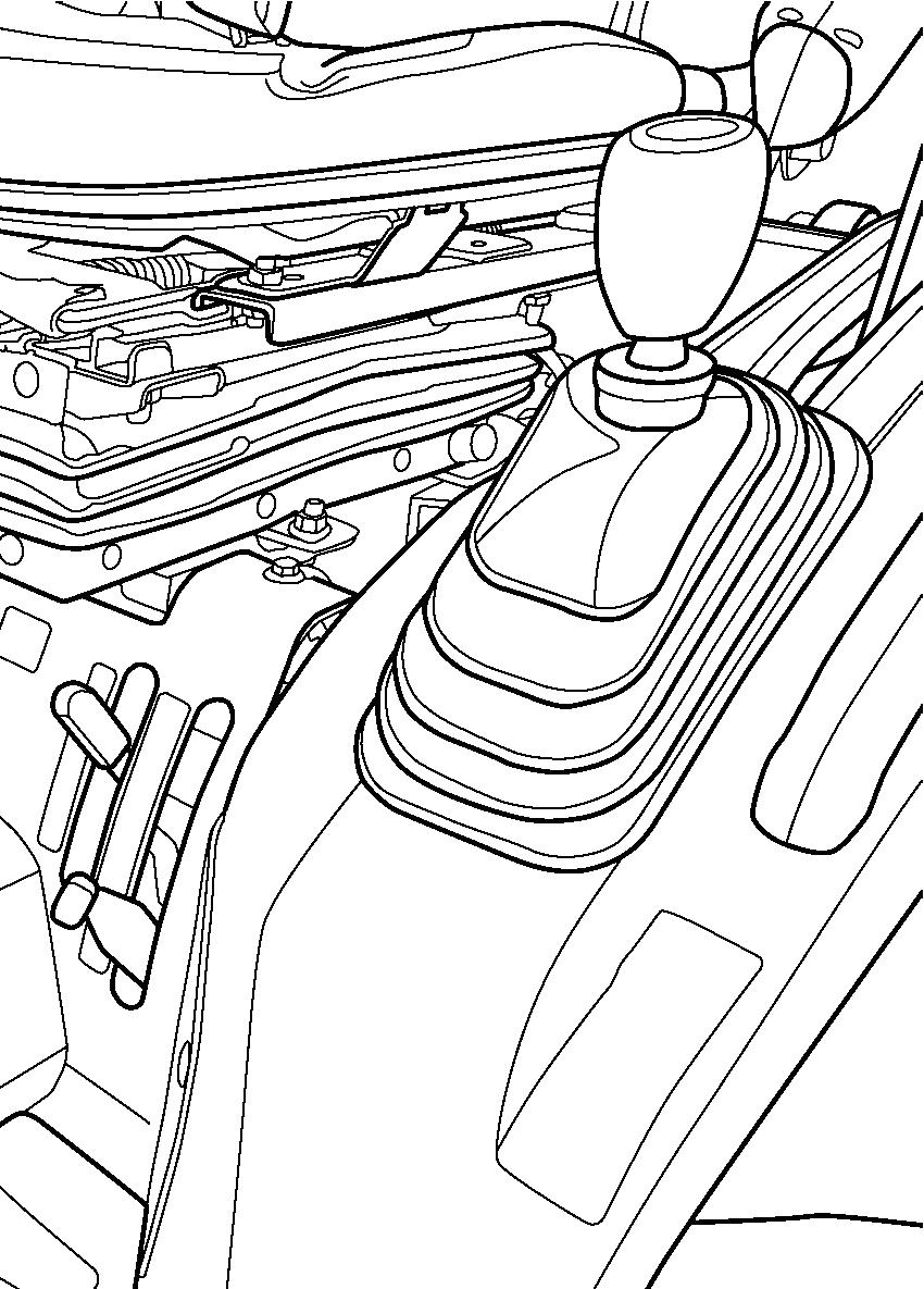
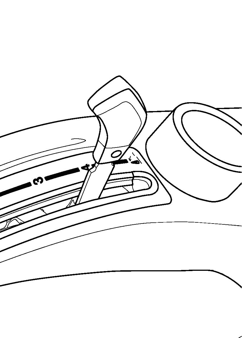
Ground Speed Selection
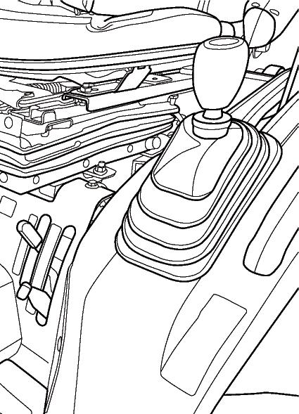
FIGS. 52 & 53: Tractor is equipped to provide 6 forward gear speeds and 2 reverse gear speeds.
Main gearshift lever (1) provides a 3 forward and 1 reverse gear selection. These gear selections provide small changes in ground speeds.
Range gearshift lever (2) provides major changes in ground speeds.
To start forward / reverse travel, the tractor travel must be stopped. Depress the clutch pedal and position gearshift levers in desired positions. Release the parking brake and slowly release the clutch pedal.
If another gear selection is required, stop travel and repeat the above operation.
IMPORTANT: All range and gear change selections require complete disengagement of main clutch (depressing pedal).
TABLE 2: Arrangement of gears with appropriate ground speeds, in order from slow to fast, are shown in chart below.
(Engine revolution speed: 2 700 min-1)
Stopping Tractor
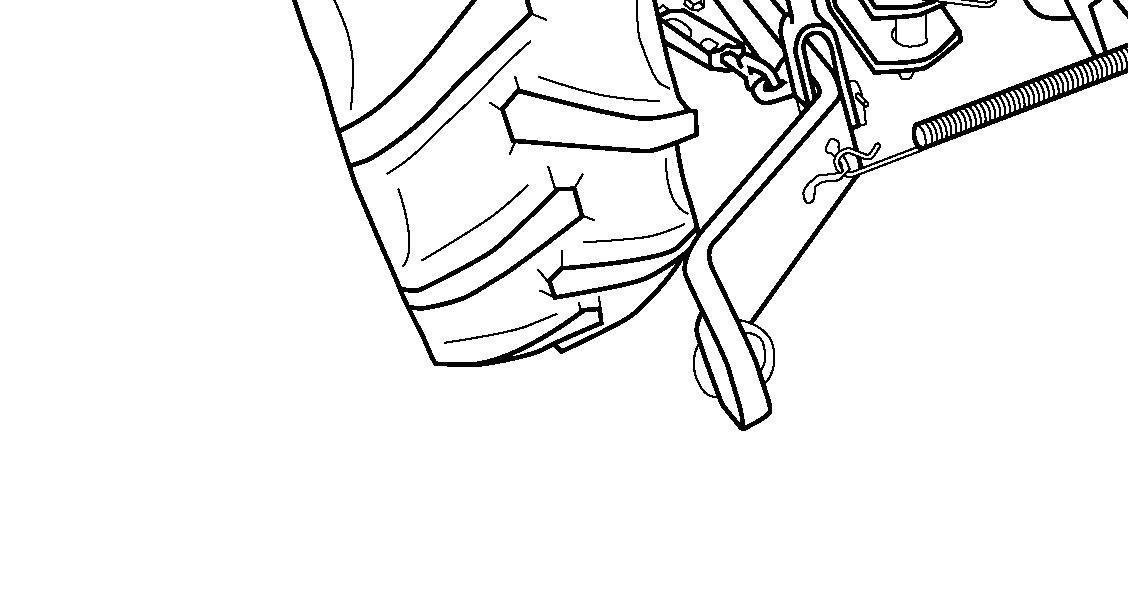
FIG. 54: Brake pedals (1 and 2) may be used independently to operate respective brake and assist turning at low speed operation. Unlatch brake pedals and use as required to assist turning.
When traveling on roads or operating at high speed, brake pedals must be latched together with interlocking plate (3), so both brakes will apply at the same time.
CAUTION: Do not use individual wheel brakes, and latch brake pedals together using interlocking plate when traveling on roads or operating at high speed. Make sure brakes are adjusted evenly.
FIG. 55: To stop the tractor, move the throttle lever (1) rearward, to reduce engine speed and slow travel. Depress the clutch pedal (2) and brake pedal (3) to stop. Move the main gearshift lever (4) and range gearshift lever (5) in the neutral position. Pull the parking brake lever (6).
Allow the engine to idle several minutes for cooling down, and then turn the main switch to the “off” position shutting off the engine. Lower the 3-point hitch and remove the main switch key. Be sure to latch the brake pedals together.
CAUTION: Before leaving the tractor unattended, make sure parking brakes are applied, rear mounted implement is lowered to the ground and the key is removed from the main switch.
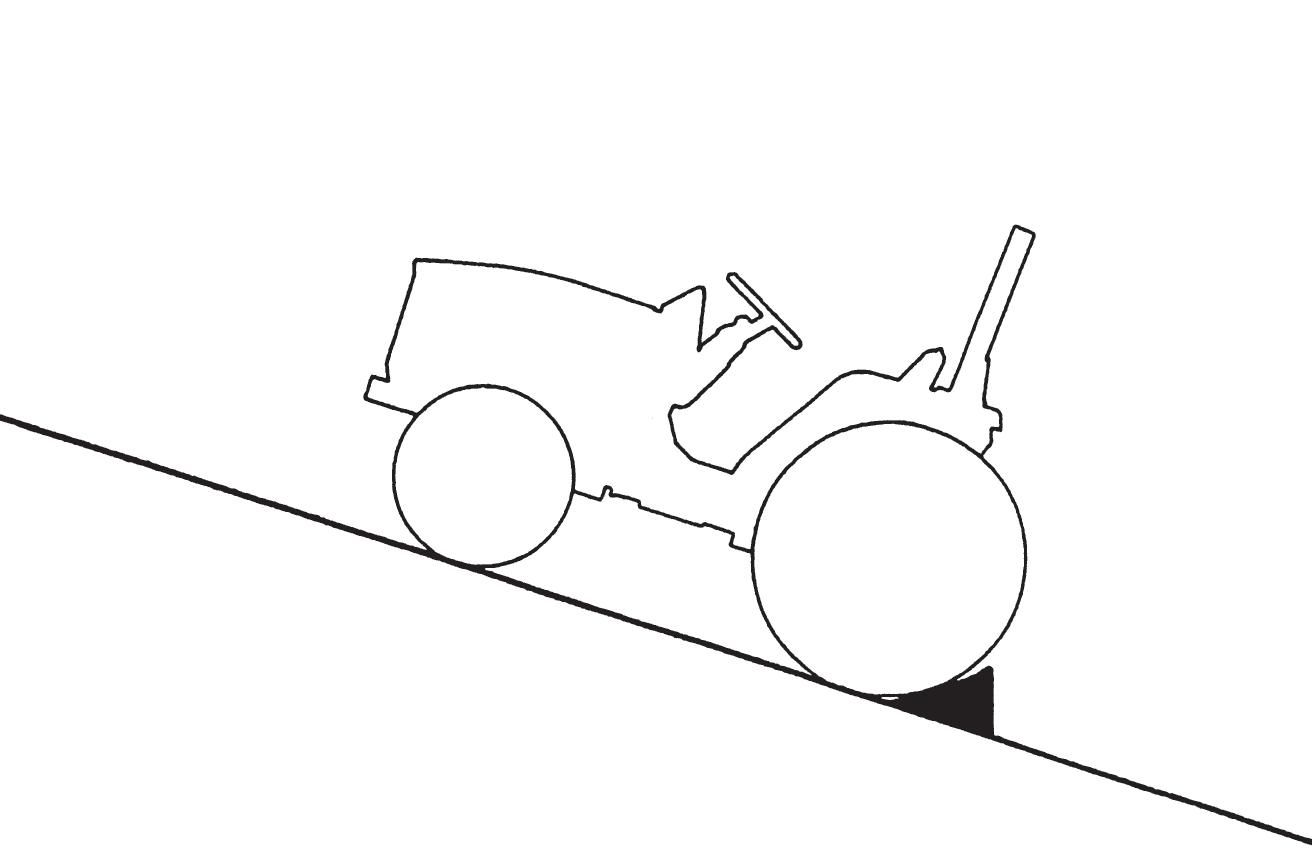
FIG. 56: Always park the tractor on level ground whenever possible. If hillside parking is necessary, securely block both rear wheels as shown.
NOTE: When stopping or parking tractor, make sure that the parking brake is applied.
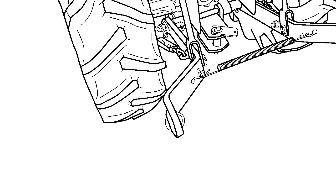
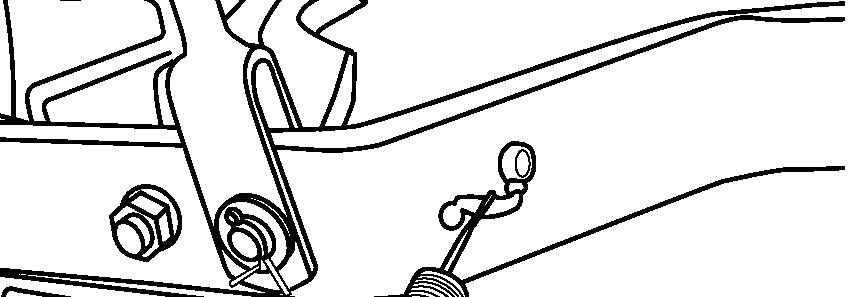
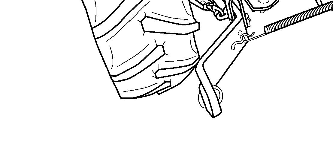
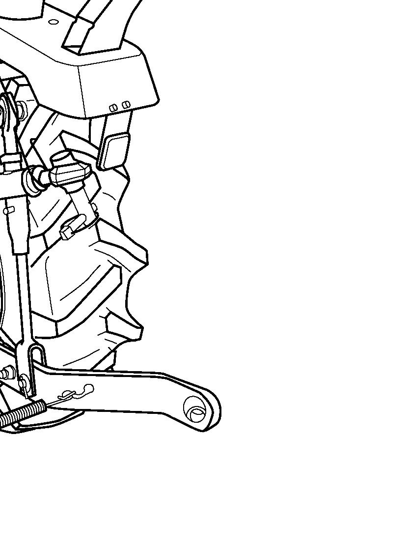
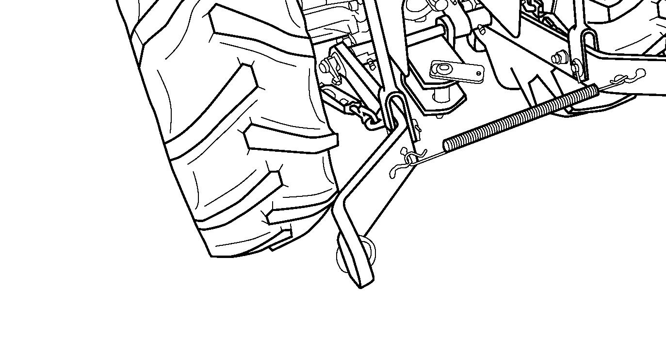
Differential Lock Operation
FIG. 57: When differential lock pedal (1) is depressed, both rear axles are locked together to provide equal traction to both rear wheels. This is especially important when operating in loose soil or slippery conditions.

To engage the differential lock, depress the clutch pedal and allow all rear wheel movement to stop. Depress the differential lock pedal and slowly engage the clutch.
To disengage the differential lock, depress the clutch pedal. The differential lock pedal should normally return to the “off” position.
IMPORTANT: Depress the clutch pedal and stop the tractor before engaging the differential lock.
NOTE: On occasion, differential lock pedal may remain engaged due to torque difference exerted by rear wheels. In this case, tap brake pedals alternatively while tractor is slowly in motion to release the pedal.
CAUTION: When the differential lock is engaged, steering ability of the tractor will be greatly reduced. Disengage before attempting a turn. Do not use during traveling on road.
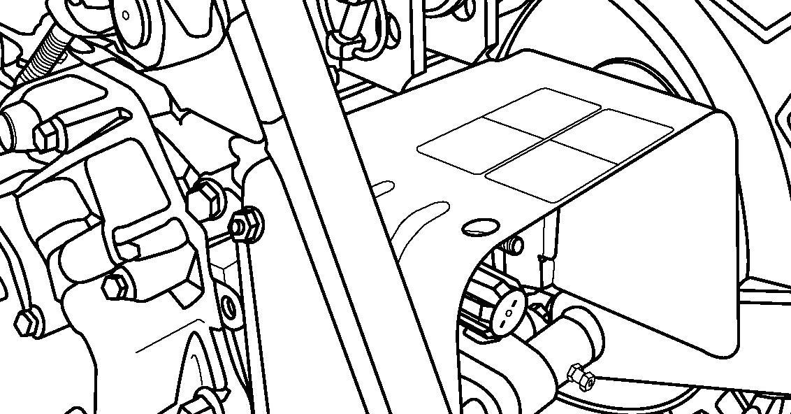
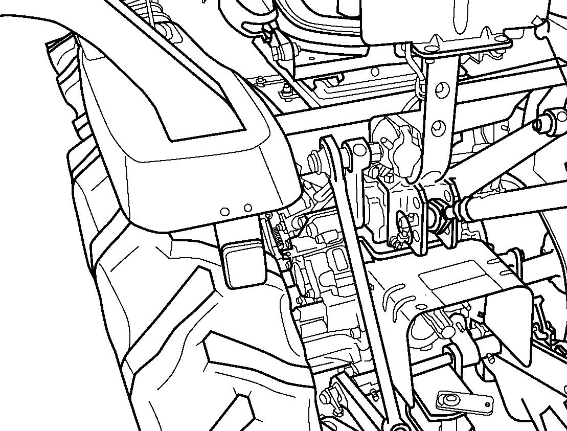
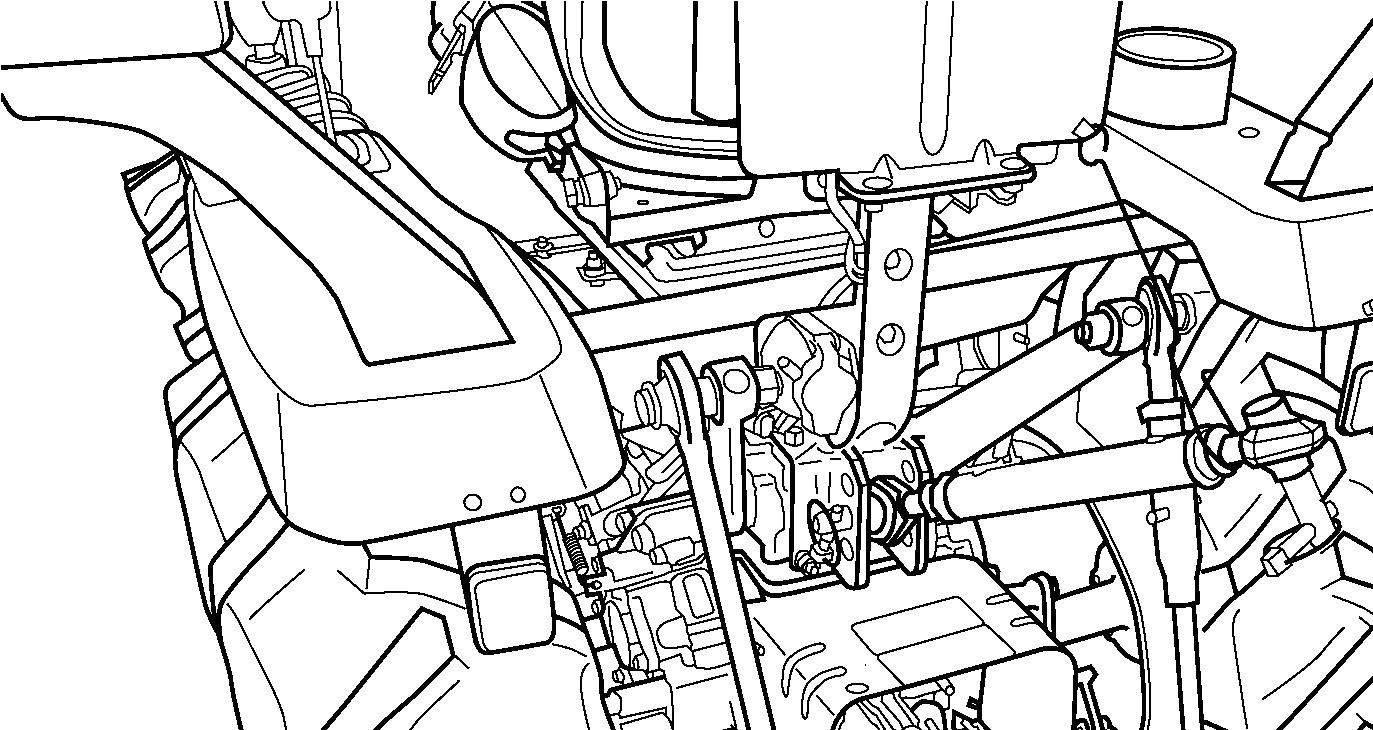
4-WHEEL DRIVE
FIG. 58: Tractor has a mechanically driven front axle. 4WD shift lever (1) engages and disengages drive for the axle.


With the lever up, the front axle (4WD) is disengaged. With the lever down, the front axle is engaged, and power is available to both front and rear axles.
IMPORTANT: Depress the clutch pedal and stop the tractor before engaging or disengaging 4-wheel drive. Do not use 4WD on hard surfaces. Rapid wear of the front tires and possible drive line damage could occur if 4WD is operated for prolonged periods on hard surfaces.
FIG. 59: When the front axle drive is engaged, the ground speed of the front tires will vary from that of rear tires. This is to assist steering when 4-wheel drive is selected.

For this reason, the front axle must be disengaged when the tractor is traveling on road or operating on a hard, dry surface. Failure to do so will result in rapid wear of the front drive tires and possible driveline damage.
IMPORTANT: Always disengage front drive axle when operating in conditions with minimal wheel slippage (DRY OR HARD SURFACES).
If tire replacement is necessary, identical replacements must be installed to maintain correct front / rear axle ratio.
POWER TAKE-OFF (PTO)
Rear PTO Shaft
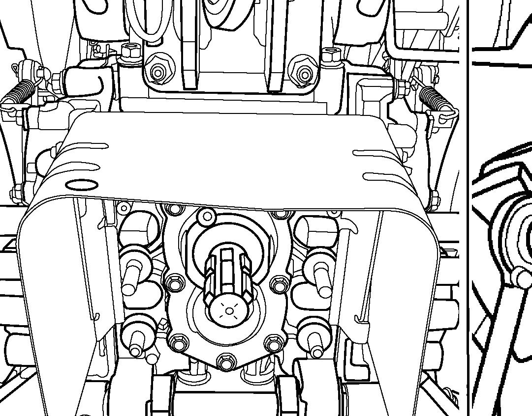
FIG. 60: PTO shaft (1) (6 splines, 35 mm (1-3 / 8”)) provides power to rear-mounted PTO driven implement.
PTO cap must be installed when rear PTO is not in use.
Normal rear PTO shaft operating speed: 540 PTO min-1 @ 2 576 min-1
IMPORTANT: When the rear PTO is used with a 3-point mounted equipment, it may be necessary to remove the rear hitch,2, at rear of the tractor. Some types of mounted equipment, when lowered, may allow the PTO shaft to contact drawbar.
CAUTION: Disengage the rear PTO and stop the engine prior to connecting equipment to or disconnecting it from the tractor’s PTO shaft. Make sure the drivershaft is securely locked in the annular groove of the tractor PTO shaft before starting the tractor engine.
DO NOT operate tractor without PTO shield cover installed. The shield cover protects people from injury.
Before attaching, adjusting or working on PTO driven implements, disengage the PTO, stop the engine and remove the key.
CAUTION: When using a PTO-driven implement, make sure the universal joint does not interfere with PTO shield cover.
DO NOT work under raised equipment. Before engaging a PTO-driven implement, ALWAYS carefully raise and lower the implement using Position Control. Check clearances, PTO shaft sliding range and articulation.
Ensure that all PTO safety shields are in place at all times. Do not step on the PTO shield cover.
Ensure that all PTO-driven implements are in good condition and conform to current standards.
NEVER step across any driveline. DO NOT use PTO shield cover as a step.
NEVER use the driveline as a step. NEVER wear loose fitting clothes. Keep at least your height away from a rotating driveline.

CAUTION: Make sure all PTO safety shields are installed on the tractor and equipment. Before cleaning or adjusting the tractor or PTO-driven machine, STOP THE ENGINE AND DISENGAGE PTO.
PTO Operating Controls
FIG. 62: The rear PTO is engaged and disengaged by using the rear PTO lever (1). When the lever is in the downward position, the rear PTO is disengaged. When the lever is in the upward position, the rear PTO is engaged.

The tractor has a single clutch. With the PTO engaged and transmission gears selected, the PTO will start turning and the tractor will start moving forward as the clutch is released.
To select the rear PTO, push the clutch pedal completely down to disengage drives to the PTO and transmission. Move the rear PTO lever (1) to upward position, and the gearshift levers to selected gear Release the clutch pedal at slow engine speed to start the PTO and forward travel, then increase engine speed to obtain the required PTO speed.

3-POINT HITCH
3-point hitch combines the tractor and implement into 1 working unit. Implement positioning and raising are controlled hydraulically. In addition, implement weight and loads impose downward pressure to the tractor rear wheels to increase traction.
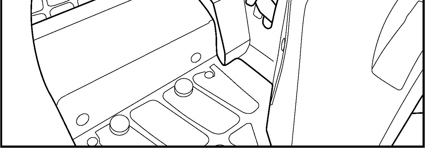
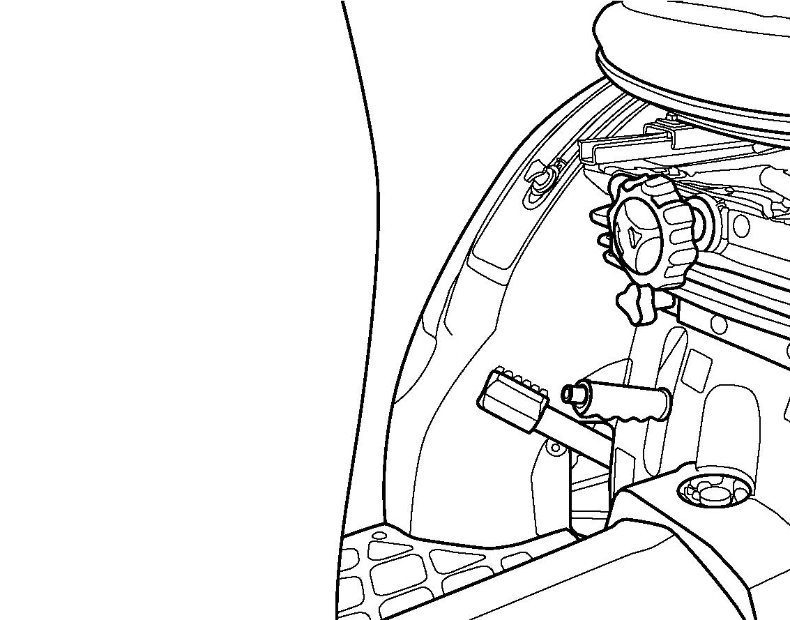
Hitch Controls
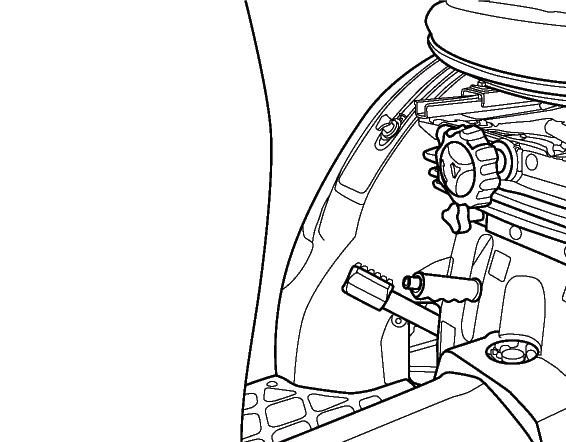
FIG. 63: 3-point hitch position control lever (1) maintains the hitch position at constant height in relation to the tractor. As the position control lever (1) is moved rearward, the hitch (and implement) are raised. Moving the lever forward will lower the hitch to the selected position. Each lever setting provides a specific hitch (and implement) position.
Front lever stop (2) can be adjusted within slot to limit implement lowering.

To limit the lowering height at suitable position for the implement set the front lever stop (2). This enables the implement to be returned to same position after the hitch has been raised when turning the tractor and traveling on road.

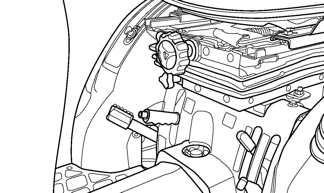
FIG. 64: Lowering rate control handle (3) controls the discharge rate of hydraulic oil thus adjusting lowering speed of the hitch and implement. Turn the handle clockwise to slow drop rate (increase lowering time), and counterclockwise to increase drop rate (decrease lowering time). Turning the handle fully clockwise will lock the implement in the raised position.
CAUTION: When working on or around mounted implements, always lower them to ground prior to work. If an implement must be raised, always block the implement and the lower links securely.
CAUTION: Always shut off the PTO and shut off the tractor engine before servicing any PTO-driven implement. Allow all movement and motion to stop before leaving operator’s seat.
NOTE: When starting the engine, make sure that the implement is lowered to the ground. This reduces load on the starter due to hitch trying to rise when the engine is cranked.
Rear Linkage
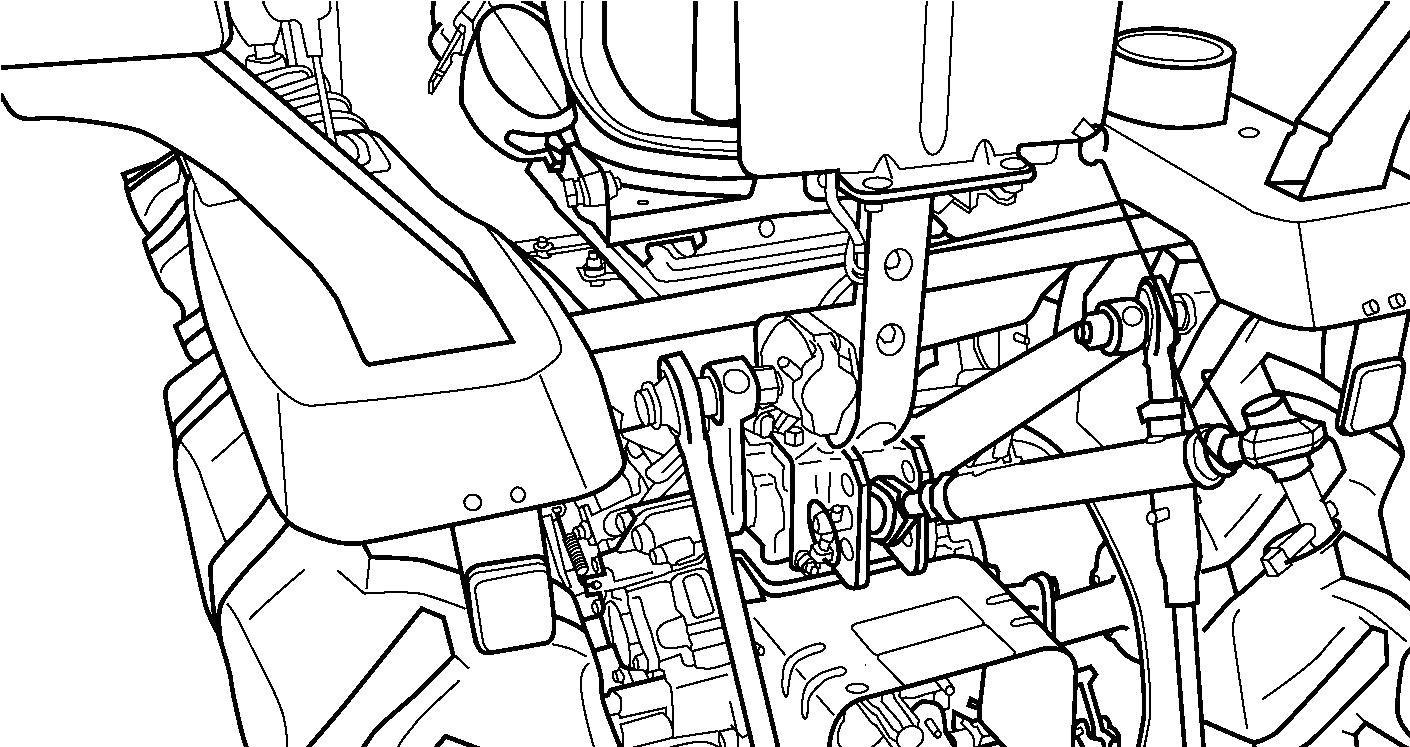
FIG. 65: Linkage consists of several major components for implement attachment and operation:
Lower links (1) - Primary attaching points to lower implement pins.
Lift rods (2) - Connect the lower links to the hydraulic lift arms for raising / lowering of the lower links. The lift rod connected to the right lower link has provisions for leveling the implement (side to side).
Check chains (3) - Reduce side sway of the implement.
Top link (4) - Adjustable, turn-buckle type to level implement (from to rear).
Spring (5) - Secures the lower links together to prevent tire interference when the hitch is not used such as traveling on the road.
FIG. 66: Linkage provides 3 positions of connecting the top link (1) to the tractor.

For most implements, securing the top link (1) in the middle hole A is satisfactory, but position may be varied to provide increased implement height during transport.
FIG. 67: To match variety of implements, rear linkages standardized according to spacing, pin size, etc. This enables usage of different implements with minimal adjustment as long as matching size or “Category” is suitable for the tractor.
This tractor is equipped for “Category 0” implements with following attaching point dimensions:
TABLE 3: Attaching point dimension
Ref.DescriptionDimension (Size)
ALower Link Width565 mm (22.2 in)
B Lower Link Pin Diameter 22 mm (0.9 in)
CTop Link Height410 mm (16.1 in)
DTop Link Pin Diameter19 mm (0.7 in)
CAUTION: Make sure that all pins after adjustment is made. Always use pins supplied with the tractor.
WARNING: Stay clear from the area of the rear linkage system when controlling it.
NOTE: When using implements with PTO shafts, adjust the height and width of 3-point to have clearance between implement and 3-point linkage. Also check any interference with the master shield.
Attaching Implements
CAUTION: Always use 3-point hitch position control lever to attach / detach implements to provide precise control of the hitch.
FIG. 68: Reverse the tractor to the implement, centering the tractor with the implement hitch frame.


Raise or lower the hitch using the 3-point hitch position control lever (1) and align the left lower link end with the corresponding implement attaching pin. Lock the brakes, shut off the engine and remove the main switch key.
FIG. 69: Slide the ball end of the left lower link (1) over the implement pin and secure with a linchpin. Adjust height of the right lower link using the turn buckle (2). Attach and secure the right lower link (3) to the implement with a linchpin. Attach the top link (4) to the top of the implement hitch frame using the pin supplied with the tractor. Rotate the center barrel section of the top link, to lengthen or shorten it, and level the implement from front to rear. After the implement is attached, it can be readjusted for level operation using the lift rod and top link turn buckles. Ascertain all adjustments are secure.
IMPORTANT: With some “mounted” implements, it will be necessary to remove the drawbar at rear of the tractor to permit the implement to be raised and lowered without obstruction.
FIG. 70: Certain implements require minimal sideplay. The check chain (1) at each lower link should be evenly adjusted to reduce side-play to the desirable level. Do not, however, eliminate all side-play as chain or lower link damage may result.

NOTE: The amount of side-play (stabilizer chain looseness) is dependent upon the implement to be mounted and type of operation. Normally 50 mm of total side movement is desired, 25 mm to each side of the tractor center line.
Using Position Control
Attaching / detaching implements and operations requiring the implement to be kept at constant height above ground. Also used with tool bars having flexible row units and implements equipped with gauge (support) wheels.
FIG. 71: Use the 3-point hitch position control lever (1) to adjust hitch and implement position.

To Begin Work - Align the tractor and implement in field and move the position control lever (1) forward (toward DOWN). Adjust implement height using the position control lever and set the front lever stop (2) as desired.
When Turning - Move the position lever (1) rearward (toward Up) to raise the implement. Finish turning and return the lever against the lower stop to resume operation.

To Finish Work and Transport - Move the position control lever (1) fully rearward in the quadrant.
CAUTION: When using mounted implements with PTO driveline, make sure: PTO drive shaft has minimum 51 mm engagement of telescoping sections, at all hitch / implement positions.
Hitch height during raising does not bind drive shaft universal joints due to extreme drive shaft angles. Limiting raising height may be required.
PTO drive is disengaged during transport.
Detaching Implements
CAUTION: Always use POSITION CONTROL to attach / detach implements to provide precise control of the hitch.
FIG. 72: Select a level to detach and store the implement. Lower implement to ground by moving the position control lever to DOWN. If necessary, adjust the leveling crank on the right lift link to level the implement on ground.
Shut off the engine, securely lock the brakes and remove the main switch key from the tractor.
Disconnect the implement from PTO driveshaft (as applicable). Detach the top link from the implement.
Disconnect the lower links from the implement pins. Make sure the lower links are connected together with the spring (1) to prevent tire interference.
Take position in the operator’s seat, start the engine and drive the tractor clear of the implement.
NOTE: Lengthening or shortening of the top link may be required to permit disconnection from the implement.
EXTERNAL AUXILIARY HYDRAULICS (OPTION)
FIG. 73: The control lever (1) controls implement raising or lowering.
Control lever is spring-loaded to center neutral position, from normal raise or lower positions. Push the levers fully forward to hold in a detent providing a float position. Float position is used for blade operations to allow the blade to float on top of the surface. The float position is also used in some implement applications.
FIG. 74: The control valve (2) is located at the righthand side of the cylinder case. Implement hoses must be connected to each coupler set.
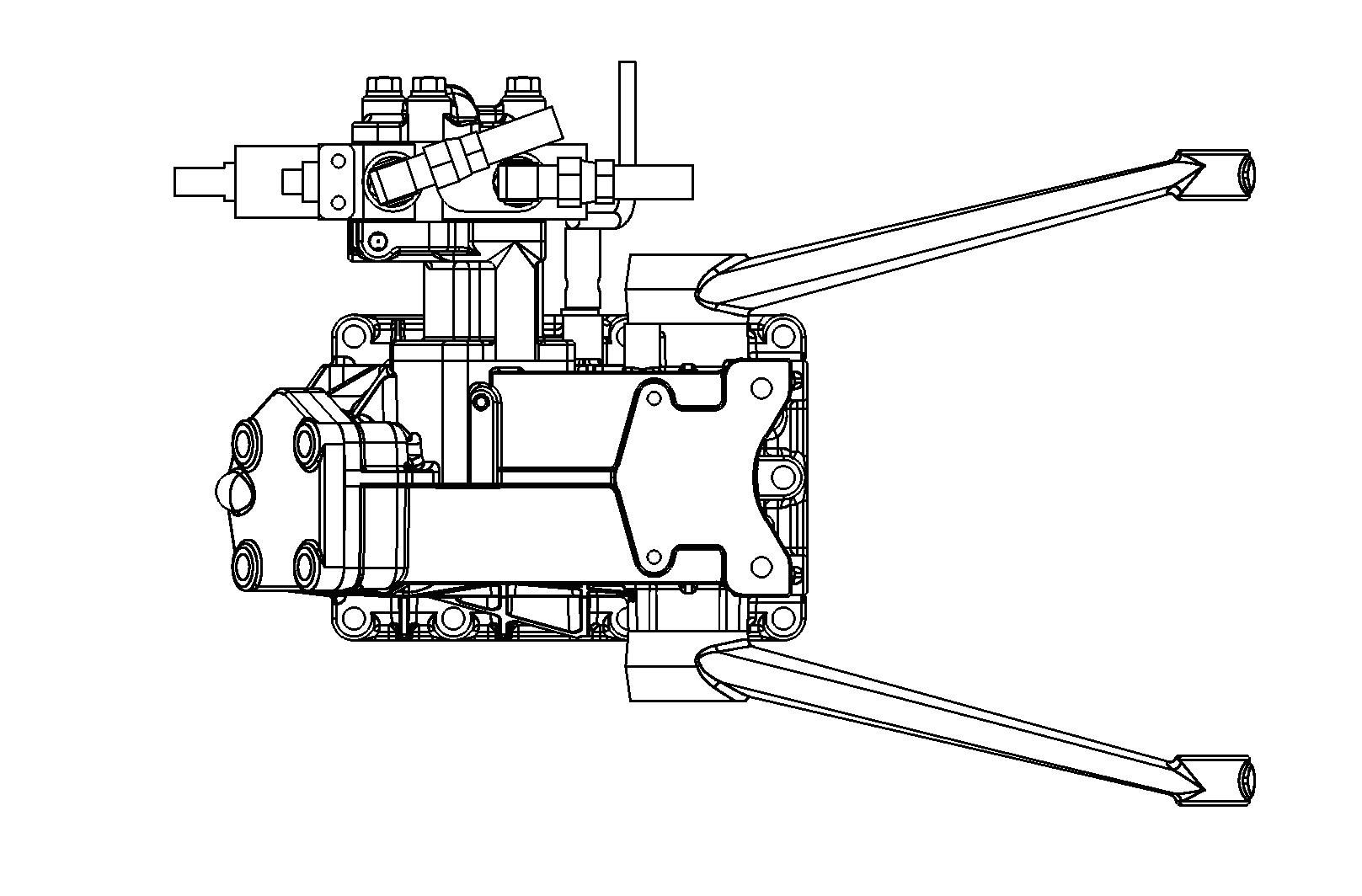
Most implements require double-acting hydraulics. Each implement cylinder will have 2 hoses connected to it. When single acting service is required, the front coupler (3) will be used.
CAUTION: Always lower implement to ground, shut off engine and relieve system pressure (by operating control levers with engine off) before connecting or disconnecting implement hoses.
CAUTION: Make sure all hydraulic hoses, couplers and cylinders are in good condition before use.
FIG. 75: The selector function (4) must be turned to the left. The selector function is located at the right rear of the tractor on the back of the valve spools.
NOTE: For normal double-acting operation selector function must be turned to the right.
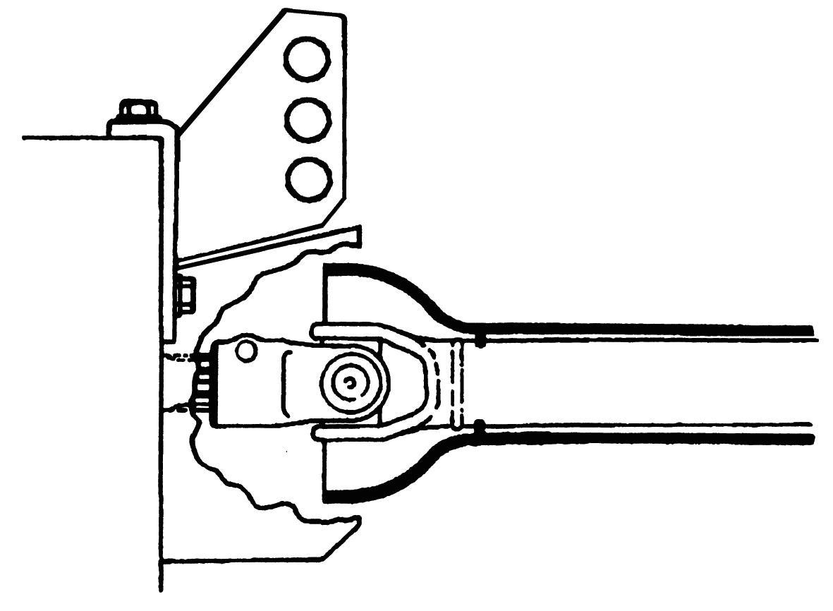
Rear Hitch
FIG. 76: E4 type tractor is equipped with rear hitch (TRH-1776A) (1). Rear hitch at rear of tractor allows towed implements to be attached to tractor. Tractor does not have any trailer braking system.
Follow strictly the instructions outlined in the operator’s manual of the mounted or trailed machinery or trailer, and do not operate the combination tractormachine or tractor - trailer unless all instructions have been followed.
Do not use non-genuine parts for towing. Otherwise, unexpected accidents may occur.
Only R type tractor can be equipped with or Scharmuller 3453 (2). (Optional) Consult your dealer.
TABLE 4: Specification of rear hitch (TRH-1776A)
Type approval No. e13*2015/208*2016/1788 NS*00027*00
Maximum horizontal loadNot applicable
Towable mass1 500 kg
Maximum permissible vertical load on the coupling point 500 kg
TABLE 5: Keep the maximum vertical load on the rear hitch, related to the rear tire size and type of hitch.
TABLE 5: Maximum vertical load
TM3185F3
TRH-1776A
Tire Size Without front weight (kg)With front weight (kg) FrontRear Rear ROPS
5-12Agri 8-16150-160500
5.00-12Agri 9.5-16 180-195500 Turf 20X8.00-10Turf 215/80D-15120-130500
TABLE 6: Keep the permissible towable mass. When towing trailer, stay clear from the area between tractor and trailed vehicle.
TABLE 6: Permissible towable mass
TRH-1776A
Towable mass
Total technically permissible towable mass (kg)
Total technically permissible masses of the tractor - trailer combination for each configuration of trailer braking (kg)
ROLL OVER PROTECTIVE STRUCTURE (ROPS)
FIG. 77: ROPS type tractor is equipped with a roll over protective structure (ROPS) (1) and seat belt. The seat belt must be worn at all times when the tractor is being operated with the ROPS in the upright, locked position.
The ROPS can be folded down only in the limited work such as going into and out from building, and work within orchard, hop or vineyard. After the work, return the ROPS to the upright position.
WARNING: Except for the limited work such as going into and out from building and work within orchard, hop or vineyard, do not operate the tractor with the ROPS folded down. Otherwise, this may result in serious injury when the tractor rolls over.
CAUTION: Do not use the seat belt when the ROPS is folded down.
How to Tilt ROPS
FIGS. 78 & 79: When overhead clearance is low, the upper portion of the ROPS can be folded down.
To fold the upper portion of the ROPS, remove the locking pin (1) and pin (2). Loosen the lock nuts (3) and the knob (4) on both sides of the ROPS frame, and then lower the upper portion of the ROPS.
The seat belt must not be fastened when operating with the ROPS folded down.
WARNING: No roll-over protection is provided when the ROPS is folded down. Drive with extreme care. Tractor roll over may result in serious injury or death.
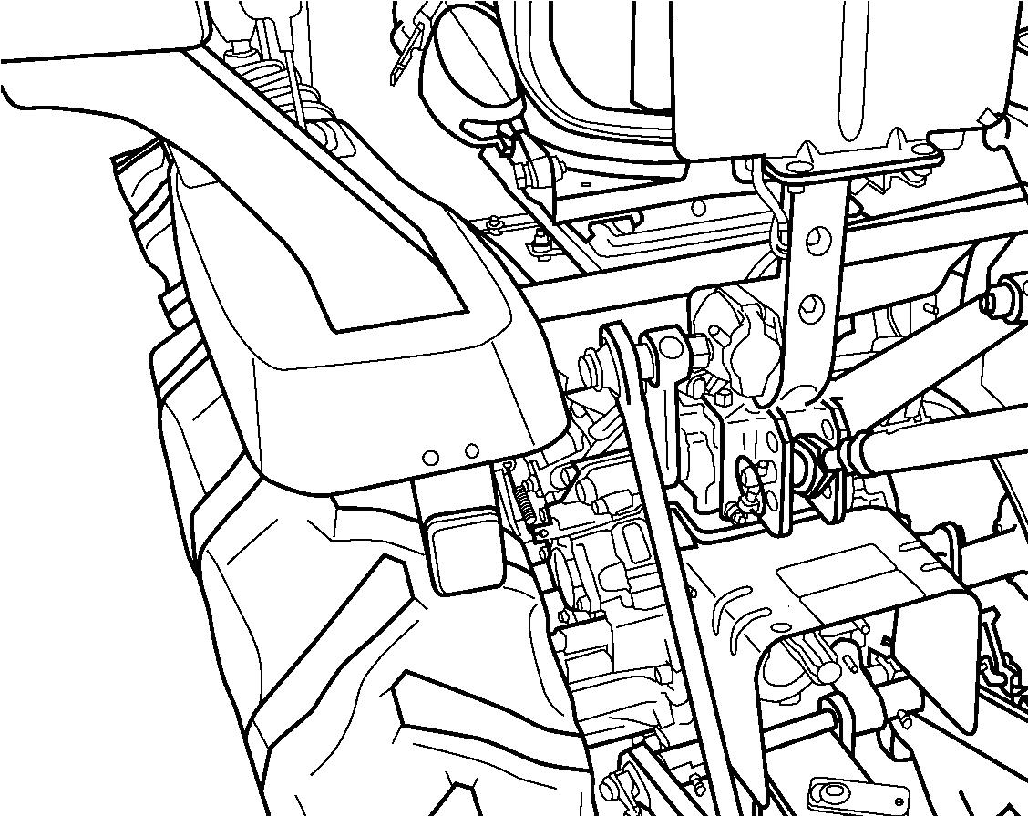
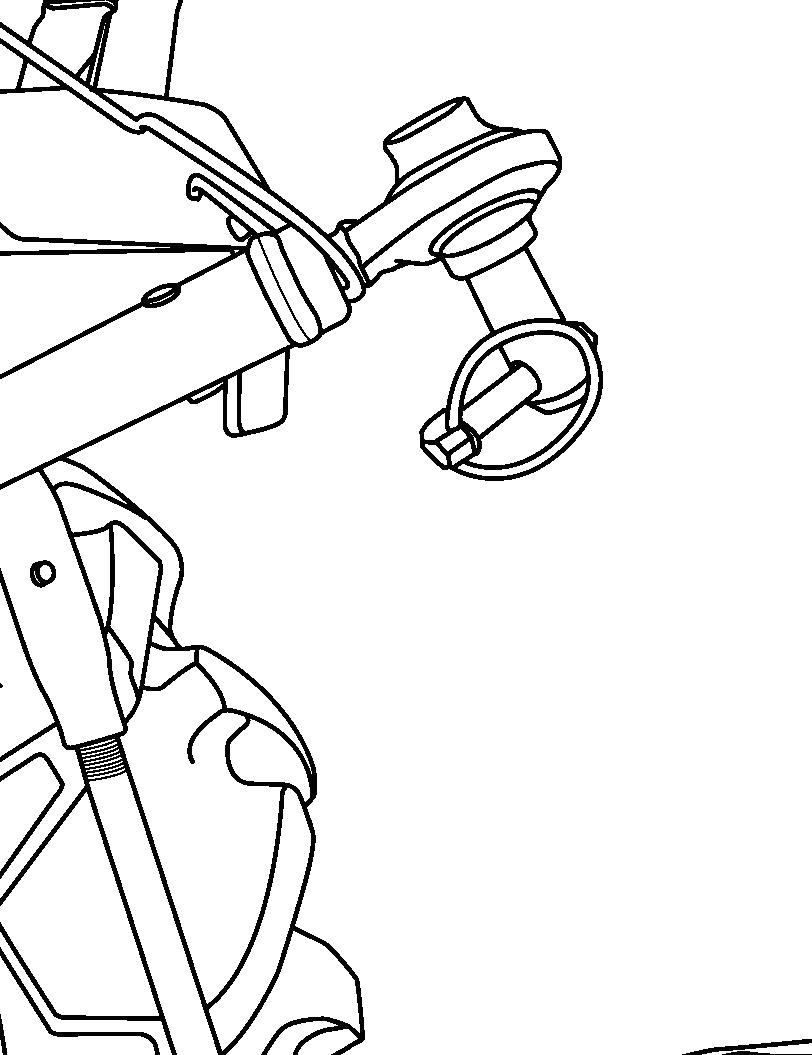
SEAT & SUSPENSION ADJUSTMENT
FIG. 80: Woochang W10SSS (Z type : Standard) (Except for Z type : Optional)
FIG. 81: COBO GT62 / M200 (All types : Optional)
CAUTION: Make sure that the seat is adjusted before driving. Do not attempt to adjust the seat during driving to avoid unexpected accident.
WARNING: In case of installing local arrangement seat, you must connect the seat switch with the harness at tractor side. Otherwise, seat switch does not function as a safety system and this may result in unexpected accidents.
To enable the seat switch to function as a safety system correctly, consult your dealer.
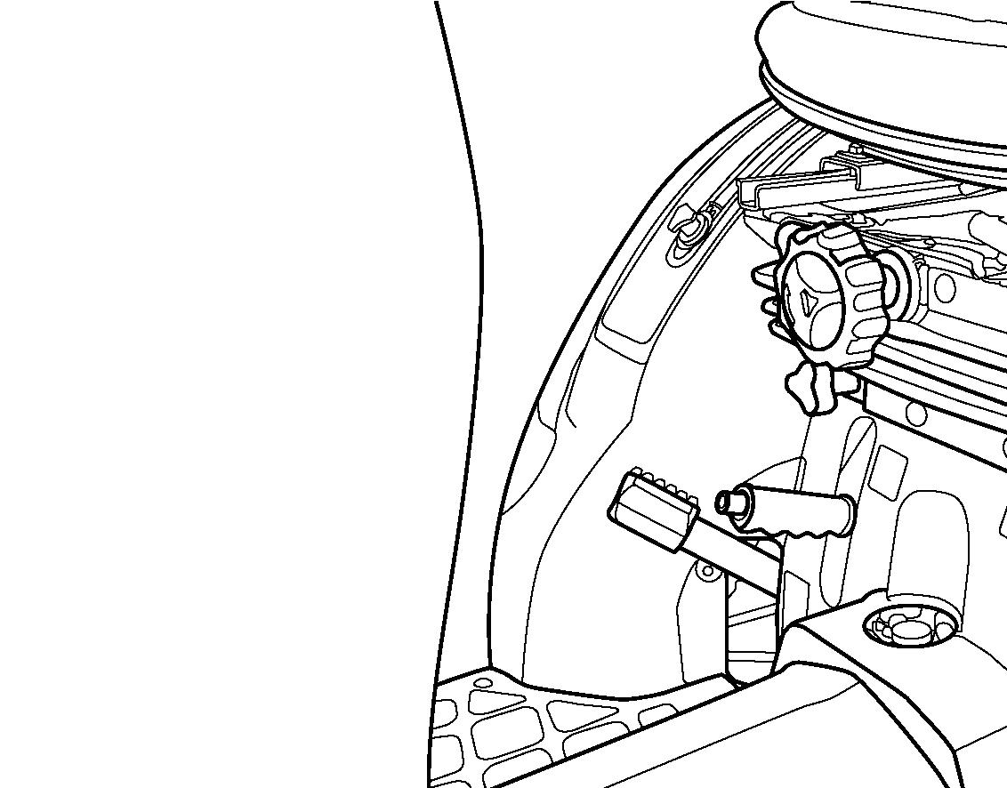
Driver’s Weight Adjustment (1) -
The seat’s suspension settings is adjusted for the driver’s weight by turning driver’s weight adjustment control.
To increase the tension position, turn the driver’s weight adjustment control clockwise, A.
To decrease the tension position, turn the driver’s weight adjustment control counterclockwise, B.
Height Adjustment (2) -
The seat height is adjusted by turning height adjustment knob.
To increase the height position of the seat, turn the height adjustment knob counterclockwise, A.
To decrease the height position of the seat, turn the height adjustment knob clockwise, B.
Fore-Aft Adjustment (3) -
The seat is slid forward or backward by pulling fore-aft adjustment lever.
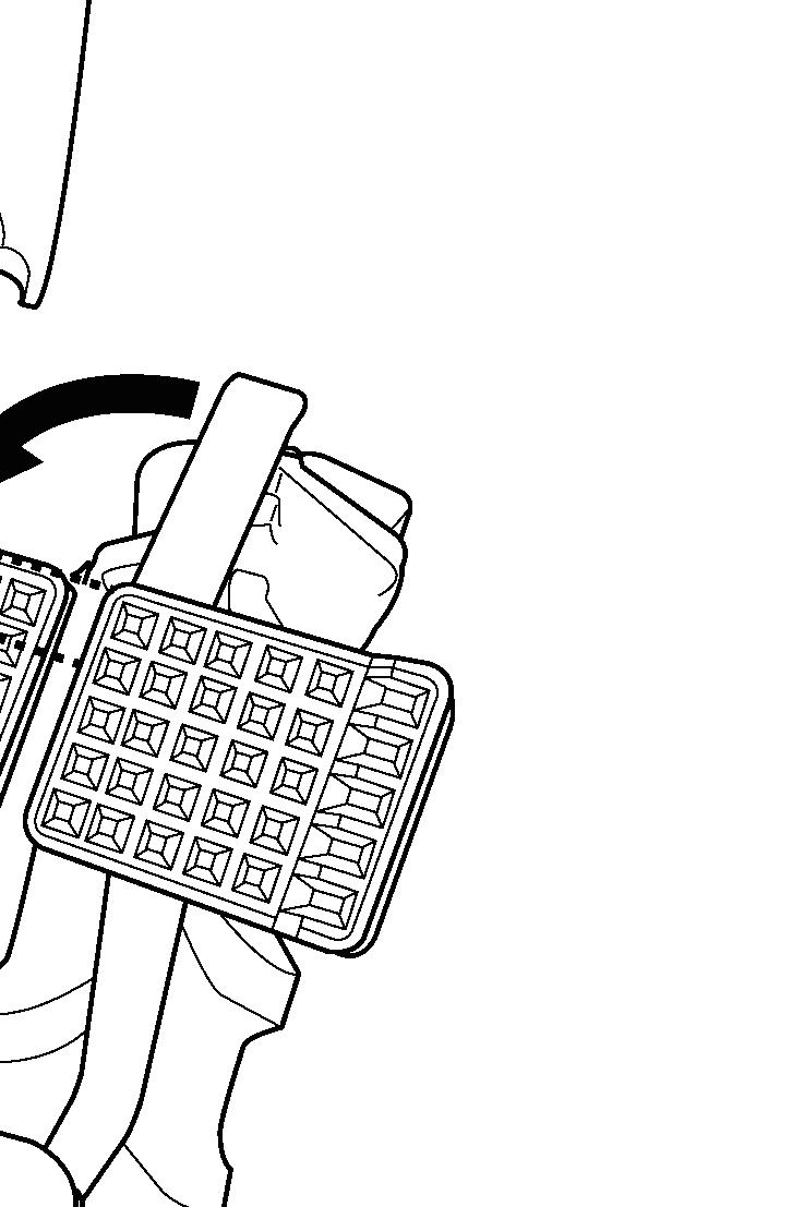
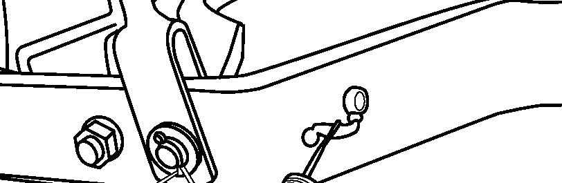
7 Pins Socket
CAUTION: Select the proper size electric wire for auxiliary power supply. Insert a fuse to the wiring for the attachment when using the smaller capacity electrical wires than the proper size. Otherwise, the fuse cannot protect the wiring if there is a short circuit, and may result in the burning of the electric wiring and cause fire.
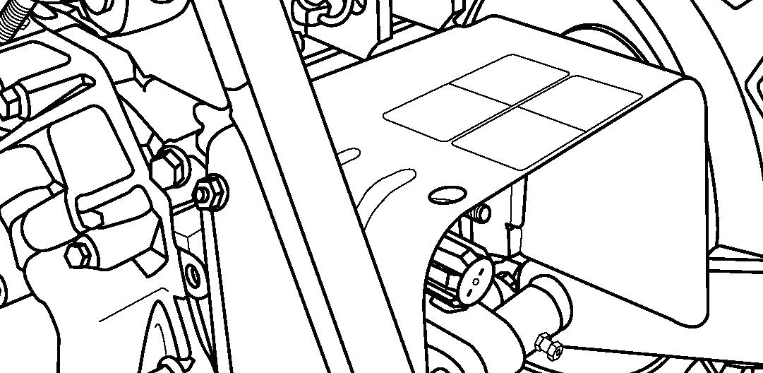
Beacon
FIG. 83: Wiring for beacon is standardly equipped.
NOTE: Beacon terminal is located at the center under part of rear frame behind the seat. It is fixed to the harness which is heading to registration plate. The wire color of beacon terminal is green and black.
Towing
Consult your ISEKI dealer for towing tractor as much as possible. If such cases as listed below, call your ISEKI dealer as transmission might be broken.
• Although the engine runs, tractor cannot start to move.
• Unusual noise occurs.

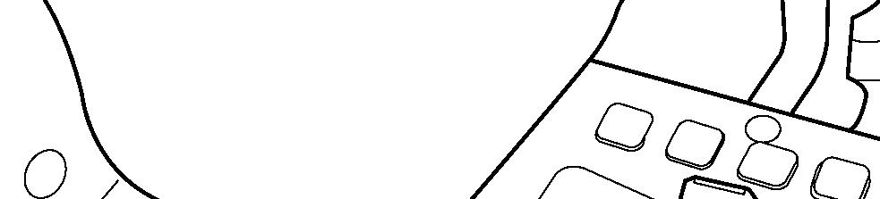
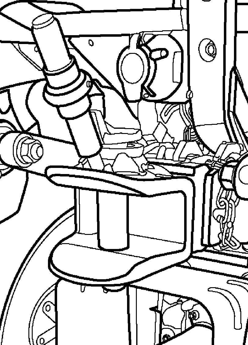
FIG. 84: Hook up the rope to the front hitch (1). The distance between towing vehicle and tractor should be less than 5 m.
Move the main gearshift lever and range gearshift lever to the neutral position. Release the parking brake lever.
Front Loader Fixation Point
Consult your ISEKI dealer concerning the fixation points on tractor for the front loader. Appropriate frames between the rear axle and the front frame might be necessary to obtain robust safety.
FALLING OBJECTS PROTECTIVE STRUCTURE (FOPS) & OPERATORS PROTECTION STRUCTURE (OPS) FIXATION POINT
Consult your ISEKI dealer concerning the fixation points on tractor for the FOPS & OPS.
NOTE: FOPS and OPS are not standard equipment.
Jacking
When jacking tractor, place the tractor on level, hard ground which is sufficiently illuminated, otherwise unexpected accidents may occur. Follow the instructions listed below:
• Apply parking brakes.
• Disengage PTO.

• Place main gearshift lever and range gearshift lever in neutral.
• Remove the key from main switch.
• Place the jack on level.
• Put tire chocks to the rear wheels when jacking up the front wheels.
• Put tire chocks to the front wheels when jacking up the rear wheels.
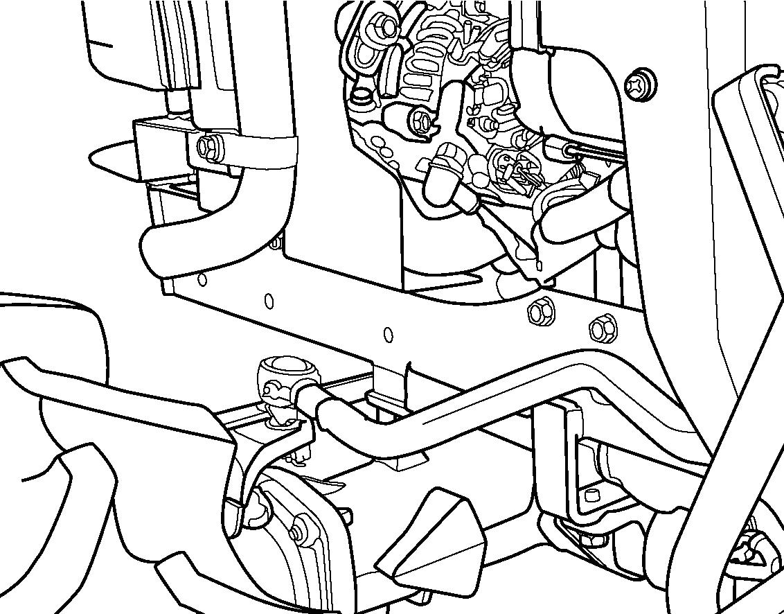
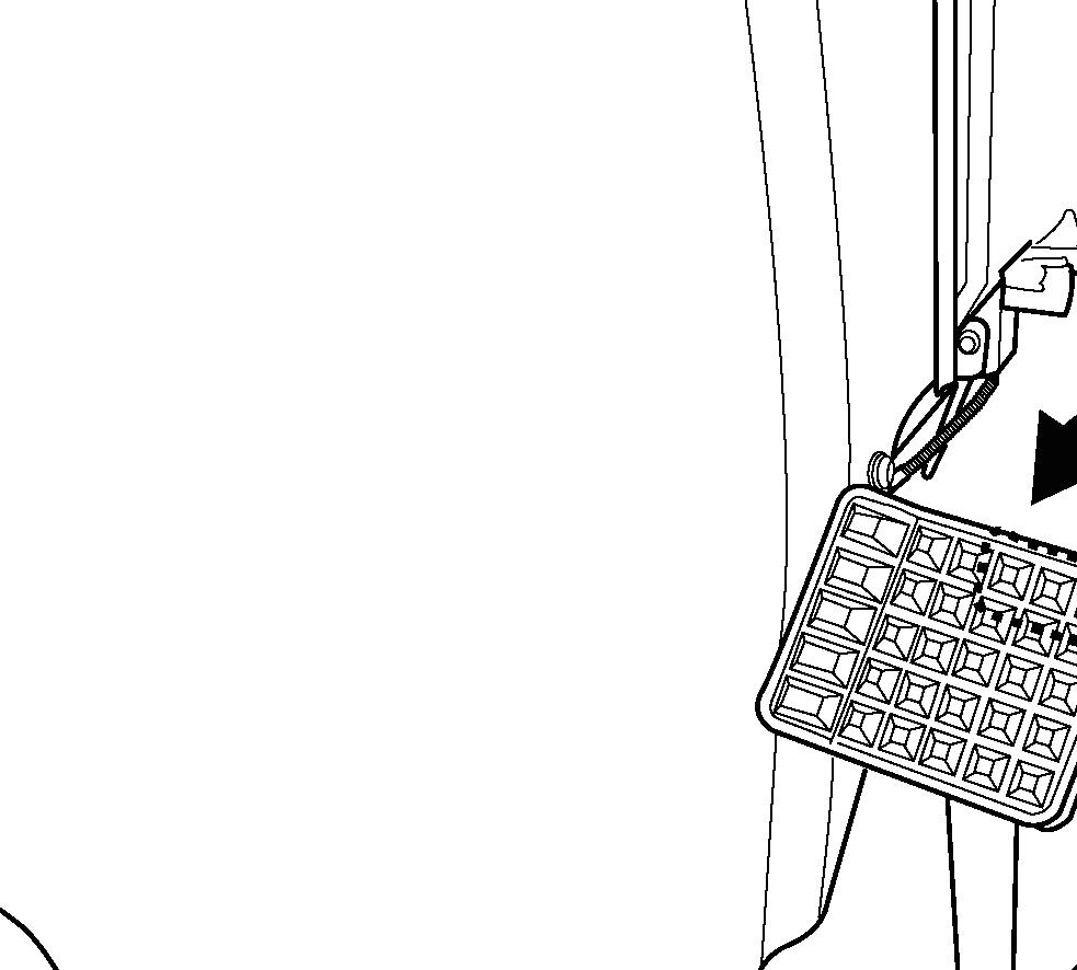
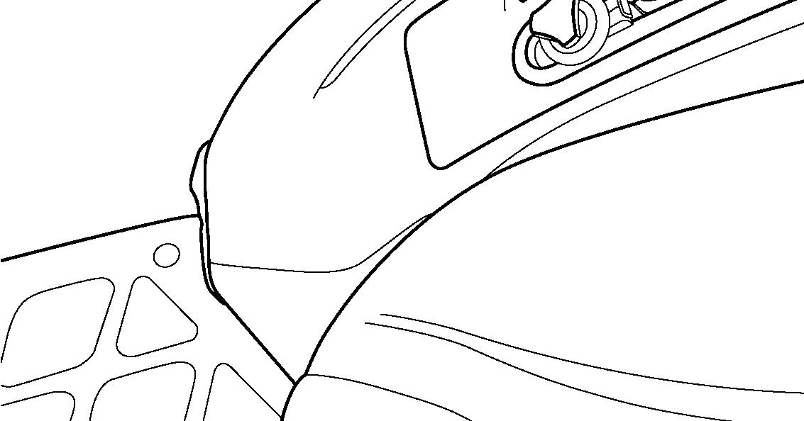
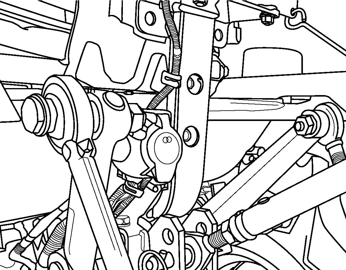
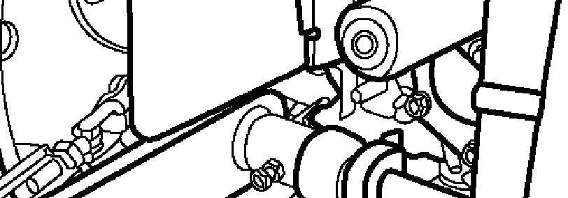
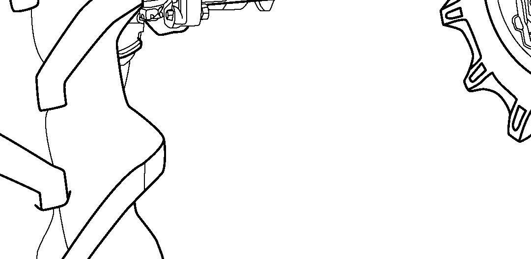
FIG. 85: When raising the rear axle, suitable shims (1) should be wedged between the front axle and the rear frame.
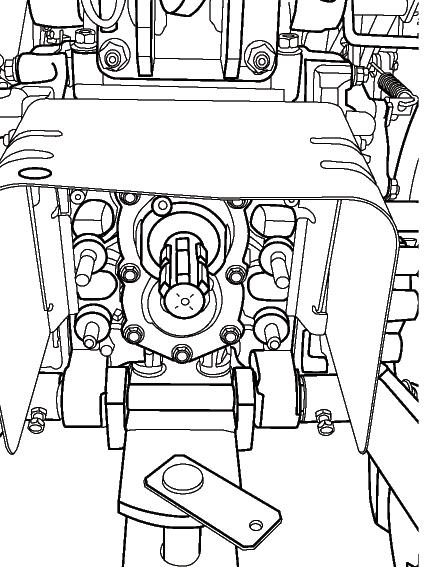
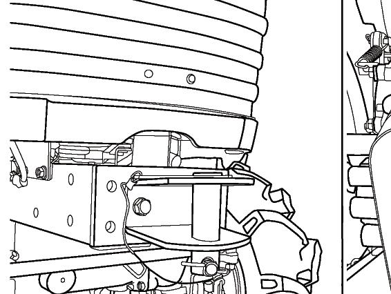
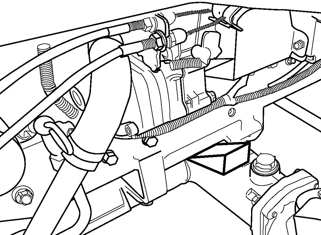
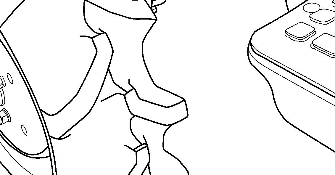
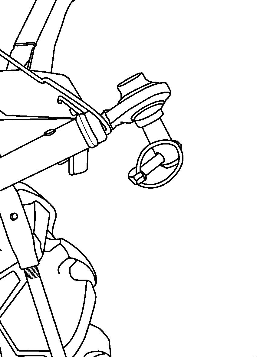
FIG. 86: When raising the front axle, the jacking point is the front hitch (1) or the front pivot (2). For the front axle, the jacking point is the rear hitch (3).