14 minute read
VOLTS 60 VOLTS 78 VOLTS


A resistance of less than one megohm indicates a problem between a winding and the armature shaft.
FIGURE 25. TEST FOR AN OPEN FIELD CIRCUIT
2 1
1.FIELD COIL TERMINAL 2.OHMMETER
11415
Test For An Open Circuit In A Field Coil
The field windings in large electric motors normally have less than one ohm of resistance. If an ohmmeter (R x 1 scale) is used to check the resistance between the two terminals of the winding, a resistance greater than one ohm indicates a problem in that winding or corrosion in the terminal connection. See FIGURE 25.
Test For A Short–Circuit In A Field Coil
A short–circuit in a motor field winding is difficult to test because of the normal low resistance (less than one ohm) of a good field. Special equipment is necessary to check for a short–circuit in a motor winding. A motor with a short–circuit in a field winding will have a different sound when it begins to operate, but a service person must have experience to hear and understand the difference in sound. A winding with a short–circuit will also run hotter than a good winding and can have indications of heat damage.
Another indication of a short–circuit will be a higher than normal current draw by the motor. A higher than normal current draw can also indicate other problems or needed adjustments and does not always indicate a short–circuit in a motor winding.
Test For A Short–Circuit Between The Field And The Motor Case
Make sure that carbon dust has been cleaned from the motor before making this test. An ohmmeter (R x 10,000 scale) can be used to test for a short–circuit between the field and the motor case. Put one probe on the motor case and the other probe on a field terminal. Check the resistance between the field terminal and the motor case. A resistance of less than one megohm indicates a problem between the field terminal and the motor case.
Brush Holder Test
Make sure the carbon dust has been removed from the brush holders. Use an ohmmeter (R x 10,000 scale) to measure the resistance between the brush holder and the motor case. The correct resistance is an indication of infinity (∞).
INTRODUCTION
GENERAL
This section has the checks, adjustments and repair procedures for the parts of the electrical system that are NOT part of the EV-100LX motor controller. This section also does NOT include the electrical components covered in other sections such as motors and battery indicators. This section applies to the electric SitDrive models J1.60-2.00XMT. To check, adjust or repair the parts of the motor controller, see the section EV-100LX
MOTOR CONTROLLER, 2200 SRM 460.
See the section BATTERY INDICATORS, 2200 SRM 138 to adjust the battery indicator. See the section
INSTRUMENT PANEL INDICATORS AND
SENDERS, 2200 SRM 143 to check and replace the other instrument panel indicators and the senders. See the section THE DC MOTOR MAINTENANCE, 620 SRM 294 for maintenance of the motors. See the section THE INDUSTRIAL BATTERY, 2240 SRM 1 for information on the battery.
NOTE: This section does NOT include any components of any of the motor controllers. Many of the components in this section do have inputs to the EV-100LX motor controllers, but are not part of the controller.
WARNING
Do not operate a lift truck that needs adjustment or repairs. Report the need for adjustment or repairs immediately. If adjustment or repair is necessary, put a “DO NOT OPERATE” tag in the operator’s area. Remove the key from the key switch. Some of the checks and adjustments are done with the battery connected. Never have any metal on your fingers, arms or neck. These metal items can accidentally make an electrical connection and cause an injury.
Some components that have inputs to the controller have installation adjustments. This section has the correct procedures for replacement, checks and adjustment of these components. These components include the following: 1.Key Switch 2.Accelerator Switch Assembly 3.Parking Brake Switch 4.Direction (FWD REV) Switches Monotrol Pedal Direction Control (on Steering Column) 5.Hydraulic Cut Off Switch 6.Brake Fluid Switch 7.Motor Temperature Switches 8.Horn and Horn Button 9.Printed Circuit Boards 10.Stop Light Switch (Optional) 11.Rocker Switches for Lights (Optional) 12.Lights and Reverse Alarm (Optional)
NOTE: Some checks and adjustments are difficult to do unless another person can operate the controls. When working alone, put a weight in the seat to close the seat switch. Put the voltmeter in a position so that you can see it from the operator area. You can usually operate the controls with your hand and also make the voltage measurements.
DESCRIPTION
INSTRUMENT PANELS
There are two instrument panel displays available on these lift trucks:
a standard display that gives the operator basic information about the operation of the lift truck and
a premium display that includes diagnostic capabilities and additional indicators about the operation of the lift truck.
Standard Display (See FIGURE 1)
When the key is first turned to the “ON” position, a start program will cause each indicator light to illuminate to show that the light is good. This instrument panel has the following components:
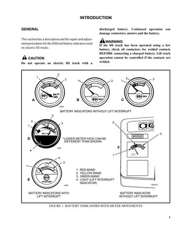
1. Hourmeter. The hourmeter display shows the operating time of 0000 to 9999 hours. The time for the traction circuit is shown for four seconds after the lift truck has been operating and the key is turned to the “OFF” position. 2. Voltmeter. This battery indicator has a green, yellow and red band to indicate the voltage of the battery. The battery must have a current draw (load) to check the battery charge. Hold the tilt lever in the tilt BACKWARD position and look at the indicator. If the needle is in the red band, charge the battery. Operating the lift truck with the needle in the red band can decrease battery life. Continued operation with a discharged battery can damage the battery, motors or the contactors.
3. Warning light, parking brake indicator. The red light is “ON” when the parking brake is applied and the seat switch is closed, and goes “OFF” when the parking brake is released.
4. Warning light, brake fluid reservoir is low. The red light is “ON” for approximately three seconds when the key switch is turned to the “ON” position and must go “OFF” during operation. If the warning light is “ON” during operation, the brake fluid level in the reservoir is too low.
1 3 4
STANDARD DISPLAY
2
BRN “BAT” TERMINAL KEY SWITCH LEADS
RED/BRN “IGN” TERMINAL STANDARD DISPLAY 18 PIN CONNECTOR
PIN FUNCTION 1-11 No Connection 12 Battery Negative ( ) 13 Hyd. Contactor Coil 14 Brake Fluid Switch 15 Parking Brake Switch 16 Seat Switch 17 Key Switch (Ign) 18 Battery Positive ( )
1.HOURMETER 2.VOLTMETER 3.WARNING LIGHT, PARKING BRAKE 4.WARNING LIGHT, BRAKE FLUID INDICATOR RESERVOIR IS LOW
FIGURE 1 – INSTRUMENT PANEL DISPLAY AND PLUG CONNECTOR
Premium Display (See FIGURE 2)
When the key is moved to the “ON” position, a start program will cause each warning and indicator light to illuminate to show that the indicator is operating. This instrument panel has the following functions:
1. Status Code Indicator. The status codes and the hourmeter values are shown on this four-digit LED display. When a fault occurs, the status code will be shown with a dash (–) in the left digit position. When the lift truck is operating correctly, the indicator will display the battery state of charge represented by numbers between 0 and 100. The status control also checks the battery voltage each time the battery is connected. The lift truck will not operate if the battery voltage is not correct.
The hourmeter display shows the operating time of 0000 to 9999 hours. The time for the traction circuit is shown for four seconds after the lift truck has been operating and the key is turned to the “OFF” position. The indicator lights for the traction motor
(5) and for the hourmeter (8) will also be illuminated during this time. If there is an SCR control card for the hydraulic pump motor, this time will then be shown on the hourmeter for another four seconds. The indicator lights for the hydraulic motor (6) and for the hourmeter (8) will also be illuminated during this time.
2. Warning Light, Parking Brake Indicator. The red light is “ON” when the parking brake is applied and the seat switch is closed, and goes “OFF” when the parking brake is released.
3. Warning Light, Brake Fluid Reservoir is Low. The red light is “ON” for approximately three seconds when the key switch is turned to the “ON” position and must go “OFF” during operation. If the warning light is “ON” during operation, the brake fluid level in the reservoir is too low.
If the parking brake is not applied and the operator leaves the seat or turns the key to the “OFF” position, a warning buzzer will make a noise for approximately 10 seconds.
4. Warning Light, Motor Brushes are Worn. When the sensor for brush wear closes, this warning light and the indicator light for the motor that has the problem will both illuminate. 5. Indicator Light, Traction Motor. This light will illuminate with another warning light if a fault occurs in the traction motor. Example: If the brush wear sensor is activated in the motor, the warning light, brush wear (4) will go “ON” and the indicator light for the traction motor will show which motor has the problem.
FIGURE 2 – INSTRUMENT PANEL DISPLAY AND PLUG CONNECTOR
PREMIUM DISPLAY 18 PIN CONNECTOR
PIN FUNCTION 1 Traction Card PY 5 2 Pump Card PY 5 3 Traction Card PY 1 4 Traction Card PY 2 5 Traction Card PY 3 6 Pump Card PY 1 7 Pump Card PY 2 8 Pump Card PY 3 9 Traction Card PY 4 10 Pump Card PY 4 11 No Connection 12 Battery Negative 13 Park Brake Switch 14 Brake Fluid Switch 15 Lift Interrupt 16 Seat Switch Input 17 Key Switch (Ign) 18 BDI Positive
PREMIUM DISPLAY
2 3 4 5 6 7 8 9
BRN “BAT” TERMINAL
KEY SWITCH LEADS 1
10
RED/BRN “IGN” TERMINAL
1.STATUS CODE INDICATOR 2.WARNING LIGHT, PARKING BRAKE INDICATOR 3.WARNING LIGHT, BRAKE FLUID RESERVOIR IS LOW 4.WARNING LIGHT, MOTOR BRUSHES ARE WORN (TRACTION, OR LIFT PUMP) 5.INDICATOR LIGHT, TRACTION MOTOR 6.INDICATOR LIGHT, LIFT PUMP MOTOR 7.WARNING LIGHT, MOTOR TEMPERATURE OVER LIMIT (TRACTION OR LIFT PUMP) 8.INDICATOR LIGHT, HOURMETER 9.WARNING LIGHT, SERVICE INTERVAL 10.INDICATOR LIGHT, BATTERY FUNCTION INDICATOR
6. Indicator Light, Hydraulic Pump Motor. This light will illuminate with another warning light if a fault occurs in either the lift pump or traction motor. Example: If the temperature over limit switch closes in the lift pump motor, the warning light, motor temperature over limit (7) will go “ON” and the indicator light ( for the lift pump motor will show that motor has the problem.
7. Warning Light, Motor Temperature Over Limit. The traction motor and the hydraulic pump motor have thermal switches inside the motors. When the temperature increases to the limit set by the manufacturer of the motor, the thermal switch closes and the warning light on the instrument panel display illuminates. The indicator light for traction motor (7) or for the hydraulic motor (8) will show which motor has the problem. The travel speed will also be decreased.
8. Indicator Light, Hourmeter: When the hourmeter indicator is illuminated, the status code will display the operating time of the lift truck. The hourmeter indicator lamp is illuminated for four seconds after the key has been turned “OFF”. If there is an hourmeter for the hydraulic pump motor, it will display for another four seconds.
9. Indicator Light, Fault: The fault indicator light will flash if the control card senses a symptom or a malfunction with the lift truck. A status code number will appear on the digital display of the status code indicator. The status number will be preceded by a dash (–) in the left digit position.
10. Indicator Light, Battery Function: The battery function indicator will flash when the status code indicator reads 19 (battery is approximately 70% discharged). The lift pump circuit will be disabled at a display of 10 (approximately 80% discharged).
PRINTED CIRCUIT BOARDS
There are two printed circuit boards used to control some of the electrical and hydraulic functions of the lift truck. The steering angle control board is located in the rear compartment and the lift pump control board, for the hydraulic control circuit, is located above and behind the hydraulic control valve.
The lift pump control board has been designed with test points to provide for easy checking of the different electrical circuits controlled by the printed circuit board.
Steering Angle Control Board (See FIGURE 3)
The steering angle board is located in the rear compartment. It is installed with the components facing downward over the steering axle assembly. Optical switches on the steering angle control board are used to determine steering angle. In addition, separate functions relative to lift pump operation and lift interrupt (contactor controlled lift pump motor only) are controlled. An internal voltage regulator allows dual voltage operation (36 or 48 volts).
The steering angle board performs several functions: 1.Monitors steering angle and supplies input to the SCR traction control for drive motor cutout and reversal during turns. Signals are generated to indicate left or right, and 35 or 85 turns.
Optical switches are mounted on the steering angle board and an interrupter (shade) is mounted to the steering axle assembly to sense steering angle.
OPT4
OPT3 OPT2 DS1
OPT1
12 9 6 3
1 P 1
BOTTOM VIEW AS INSTALLED
FIGURE 3 – STEERING ANGLE CONTROL BOARD
2.Energises the lift pump contactor, when signaled by the lift pump control board. (Contactor controlled lift pump motor only.) The optical switches on the lift pump control board supply an input to the steering angle board. A portion of the steering angle board is used to process signals from the lift pump control board. Outputs from the steering angle board connect to the lift pump contactor coil. The lift pump contactor is energised when the drivers (electronic relays) in the steering angle board complete the circuit on the negative side of the coil.
3.Provides protection against shorted pump contactor coils. (Contactor controlled lift pump motor only.)
If the current draw of a lift pump contactor coil is excessive, the output driver will turn off to protect the steering angle board. Normal operation is automatically restored when the short is removed.
4.Provides lift interrupt when the signal from the traction SCR card (PA2) is removed. (Contactor controlled lift pump motor with lift interrupt option only.)
Lift Pump Control Board (See FIGURE 4)
The lift pump control board is located above the hydraulic control valve. Optical switches on the lift pump control board are utilised to sense the position of the hydraulic control valve levers. These optical switches take the place of conventional mechanical switches. When a hydraulic control lever is moved from the neutral position, the corresponding optical switch is shaded (the light path is interrupted) and the lift pump is activated. Optical switches are shaded (the lift pump is activated) during all functions except lower. An internal voltage regulator allows dual voltage operation (36 or 48 volts). The optical switches are used to control lift pump control options: a.Single speed lift pump motor (Contactor controlled) b.Two speed lift pump motor (Contactor controlled) c.SCR controlled lift pump motor
1.On the contactor controlled lift pumps, the optical switches on the lift pump control board are connected to the steering angle control board. A portion of the steering angle control board is used to process signals from the lift pump control board. The steering angle control board is connected to the lift pump contactor coil. The lift pump contactor is energised when the steering angle control board completes the circuit on the negative side of the coil. As a separate function, the steering angle control board is used to monitor steering tyre angle and supply inputs to the traction control.
With the single speed lift pump, one contactor is used to control the lift pump motor. Outputs from the logic circuit are used to energise the lift pump contactor. When the two speen lift pump is used there are two contactors used to control the lift pump motor.
2.With the SCR controlled lift pump option, the optical switches on the lift pump control board are connected to the TB terminals on the lift pump SCR card. When a hydraulic lever is activated and an optical switch is shaded, the voltage at the corresponding TB terminal is dropped to less than 2 volts and the lift pump starts. Four separate pump speeds are provided with the SCR controlled lift pump: a.Slow lift and fourth function (Auxiliary # 2) b.Fast lift c.Tilt d.Third function (Auxiliary # 1)
FIGURE 4 – LIFT PUMP CONTROL BOARD
OTHER CONTROL COMPONENTS
Following is a short description of the other control components and their function:
Key switch is in the housing of the instrument panel and connects battery voltage to all of the control circuits except the horn. Accelerator switch assembly is actuated by the
Monotrol pedal or accelerator pedal and is part of the SRO circuit. If the accelerator switch assembly is closed before the seat switch, the controller will not permit the lift truck to move. Seat switch is inside the seat and is open if the operator is not on the seat. The seat switch sends a signal to the control card for operation of the
SCR controller and the power steering. Parking brake switch operates if the parking brake is applied. The parking brake switch is fastened near the linkage for applying the parking brake. The switch sends a signal to the control card of the instrument panel to illuminate the parking brake indicator.