2 minute read
System board

from HP 540 Notebook PC HP 541 Notebook PC Laptop Maintenance and Service Guide Manual - PDF DOWNLOAD

NOTE: All system board spare part kits include the ExpressCard assembly.
NOTE: All system board spare part kits include replacement thermal material. Replacement thermal material is also available in the Thermal Material Kit, spare part numbers 456605-001 and 456606-001.
Description Spare part number
For use only with computer models equipped with Intel Core2 Duo processors and UMA graphics subsystem
For use only with computer models equipped with Intel Celeron M processors and UMA graphics subsystem
For use only with computer models equipped with discrete graphics subsystem 495410-001
495395-001
509115-001
For use only with computer models equipped with discrete graphics subsystem 509116-001
Before removing the system board, follow these steps:
1. Shut down the computer. If you are unsure whether the computer is off or in Hibernation, turn the computer on, and then shut it down through the operating system.
2. Disconnect all external devices connected to the computer.
3. Disconnect the power from the computer by first unplugging the power cord from the AC outlet and then unplugging the AC adapter from the computer.
4. Remove the battery (see Battery on page 37).
5. Remove the following components:
a. Hard drive (see Hard drive on page 38)
b. Optical drive (see Optical drive on page 45)
c. Keyboard (see Switch cover and keyboard on page 47)
d. Switch cover (see Switch cover and keyboard on page 47)
e. Speaker (see Speaker on page 51)
f. Display lid switch module (see Display lid switch module on page 52)
g. Display assembly (see Display assembly on page 53)
h. Top cover (see Top cover on page 58)
When replacing the system board, be sure that the following components are removed from the defective system board and installed on the replacement system board:
● Memory module (see Memory module on page 43)
● WLAN module (see WLAN module on page 40)
● Processor (see Processor on page 74)
Remove the system board:
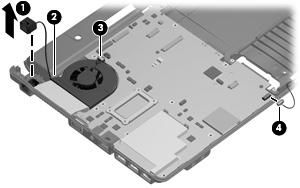
1. Remove the RJ-11 jack (1) from the clip built into the base enclosure and remove the RJ-11 jack cable from the hook (2) built into the base enclosure.
2. Disconnect the fan cable (3) and the Bluetooth module cable (4) from the system board.
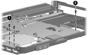
3. Remove the two Phillips PM2.0×6.0 screws (1) and the Torx T8M2.5×4.0 screw (2) that secure the system board to the base enclosure.
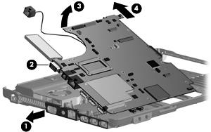
4. Flex the left side of the base enclosure (1) until the external monitor connector (2) is clear of the opening in the base enclosure.
5. Lift the rear edge of the system board (3) until it rests at an angle.
6. Remove the system board (4) from the base enclosure by sliding it back.
Reverse the preceding procedure to install the system board.