3 minute read
Display assembly

from HP 540 Notebook PC HP 541 Notebook PC Laptop Maintenance and Service Guide Manual - PDF DOWNLOAD

NOTE: All display assembly spare part kits include 2 WLAN antenna transceivers and cables.
Description Spare part number
14.1-inch, WXGA BrightView display assembly 500004-001
Before removing the display assembly, follow these steps:
1. Shut down the computer. If you are unsure whether the computer is off or in Hibernation, turn the computer on, and then shut it down through the operating system.
2. Disconnect all external devices connected to the computer.
3. Disconnect the power from the computer by first unplugging the power cord from the AC outlet and then unplugging the AC adapter from the computer.
4. Remove the battery (see Battery on page 37).
5. Disconnect the wireless antenna cables from the WLAN module (see WLAN module on page 40).
6. Remove the following components:
a. Keyboard (see Switch cover and keyboard on page 47)
b. Switch cover (see Switch cover and keyboard on page 47)
c. Speaker (see Speaker on page 51)
d. Display lid switch module (see Display lid switch module on page 52)
Remove the display assembly:
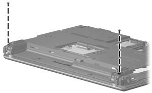
1. Close the computer and turn it upside down, with the rear panel toward you.
2. Remove the two slotted Torx ST8M2.5×7.0 screws that secure the display assembly to the computer.
3. Turn the computer right-side up, with the front toward you.
4. Open the computer as far as possible.
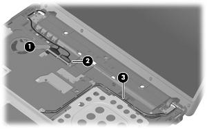
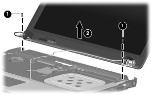
5. Disconnect the display panel cables (1) and (2) from the system board.
6. Remove the wireless antenna cables (3) from the clips and routing channels built into the top cover.
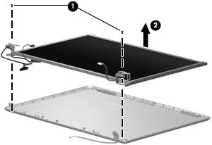
7. Remove the two T8M2.5×7.0 screws (1) that secure the display assembly to the computer.
CAUTION: Support the display assembly when removing the following screws. Failure to support the display assembly can result in damage to the display assembly and other computer components.
8. Lift the display assembly (2) straight up and remove it.
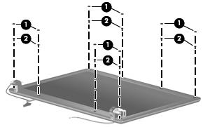
9. If it is necessary to replace the display bezel, display inverter, or display hinges, remove the eight rubber screw covers (1) and the eight Torx T8M2.5×6.0 screws (2) that secure the display bezel to the display assembly. The rubber screw covers are available in the Rubber Kit, spare part number 500132-001.
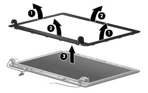
10. Flex the inside edges of the left and right sides (1) and the top and bottom sides (2) of the display bezel until the bezel disengages from the display enclosure.
11. Remove the display bezel (3). The display bezel is available using spare part number 500000-001.
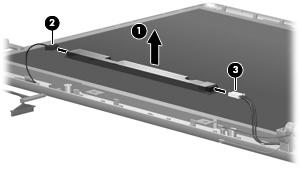
12. If it is necessary to replace the display inverter, remove the inverter (1) from the display enclosure as far as the display panel cable and the backlight cable will allow.
13. Disconnect the display panel cable (2) and the backlight cable (3) from the display inverter.
14. Remove the display inverter. The display inverter is available using spare part number 456618-001.
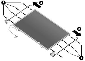
15. If it is necessary to replace the display hinges, remove the two Torx T8M2.5×6.0 screws (1) that secure the display panel to the display enclosure.
16. Remove the display panel (2).
17. Remove the four Phillips PM2.0×4.0 screws (1) that secure each display hinge to the display panel.
18. Remove the display hinges (2). The left and right display hinges are available using spare part number 456619-001.
Reverse this procedure to reassemble and install the display assembly.