2 minute read
System board


Description Spare part number
For use only with computer models with Intel Core processors and WLAN capability 448434-001
For use only with computer models with Intel Celeron M processors and WLAN capability 448433-001
For use only with computer models without WLAN capability 448432-001
Before removing the system board, follow these steps: 1. Shut down the computer. If you are unsure whether the computer is off or in Hibernation, turn the computer on, and then shut it down through the operating system. 2. Disconnect all external devices connected to the computer. 3. Disconnect the power from the computer by first unplugging the power cord from the AC outlet and then unplugging the AC adapter from the computer. 4. Remove the battery (see Battery on page 32). 5. Remove the following components: a. Hard drive (see Hard drive on page 33) b. Memory/WLAN module compartment cover (see Memory module on page 35) c. Optical drive (see Optical drive on page 39) d. Switch cover (see Switch cover on page 41) e. Keyboard (see Keyboard on page 43) f. Display assembly (see Display assembly on page 47) g. Base enclosure (see Base enclosure on page 52) h. Fan assembly (see Fan assembly on page 55) i. Heat sink (see Heat sink on page 57) When replacing the system board, be sure that the following components are removed from the defective system board and installed on the replacement system board: ● Memory module (see Memory module on page 35) ● WLAN module (see WLAN module on page 37) ● RTC battery (see RTC battery on page 54) ● Processor (see Processor on page 59) ● PC Card assembly (see PC Card assembly on page 65)
Remove the system board: 1. Remove the Phillips PM2.0×3.0 screw that secures the system board to the top cover.
2. Lift the left side of the system board (1) until it rests at an angle. 3. Flex the right side of the top cover (2) until the external monitor connector clears the opening in the top cover. 4. Remove the system board (3) by pulling it away from the top cover at an angle until it clears the top cover.

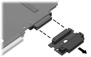
5. If it is necessary to replace the optical drive connector board, pull the board away from the system board until it disconnects from the system board.
NOTE: The optical drive connector board is available using spare part number 441631-001. Reverse this procedure to install the system board.