16 minute read
5 Lubrication


5.1 GENERAL
Following the designated lubrication procedures is important in ensuring maximum crane lifetime and utilization. The procedures and lubrication charts in this section include information on the types of lubricants used, the location of the lubrication points, the frequency of lubrication, and other information.
The service intervals specified are for normal operation where moderate temperature, humidity, and atmospheric conditions prevail. In areas of extreme conditions, the service periods and lubrication specifications should be altered to meet existing conditions. For information on extreme condition lubrication, contact your local Manitowoc/Grove distributor or Manitowoc CraneCARE.
CHASSIS GREASE LUBRICANTS MUST NOT BE APPLIED WITH AIR PRESSURE DEVICES AS THIS LUBRICANT IS USED ON SEALED FITTINGS.
Arctic Conditions
Below -18° C (0° F)
THE MULTIPURPOSE GREASE INSTALLED DURING MANUFACTURE IS OF A LITHIUM BASE. USE OF A NON-COMPATIBLE GREASE COULD RESULT IN DAMAGE TO EQUIPMENT.
In general, petroleum based fluids developed especially for low temperature service may be used with satisfactory results. However, certain fluids, such as halogenated hydrocarbons, nitro hydrocarbons, and phosphate ester hydraulic fluids, might not be compatible with hydraulic system seals and wear bands. If you are in doubt about the suitability of a specific fluid, check with your authorized Manitowoc/Grove distributor or Manitowoc CraneCARE.
Regardless of temperature and oil viscosity, always use suitable start-up procedures to ensure adequate lubrication during system warm-up.
5.2 LUBRICATION POINTS
A regular frequency of lubrication must be established for all lubrication points. Normally, this is based on component operating time. The most efficient method of keeping track of lube requirements is to maintain a job log indicating crane usage. The log must use the engine hour- meter to ensure coverage of lube points that will receive attention based on their readings. Other lubrication requirements must be made on a time basis, i.e. weekly, monthly etc.
All oil levels are to be checked with the crane parked on a level surface in transport position, and while the oil is cold, unless otherwise specified.
On plug type check points, the oil levels are to be at the bottom edge of the check port.
On all hoists with a check plug in the drum, the fill plug shall be directly on top of the hoist, and the check plug level.
All grease fittings are SAE STANDARD unless otherwise indicated. Grease non-sealed fittings until grease is seen extruding from the fitting. 0.28 kg (1 oz) of EP-MPG equals one pump on a standard 0.45 kg (1 lb) grease gun.
Over lubrication on non-sealed fittings will not harm the fittings or components, but under lubrication will definitely lead to a shorter lifetime.
On sealed U-joints, care must be exercised to prevent rupturing seals. Fill only until expansion of the seals first becomes visible.
Unless otherwise indicated, items not equipped with grease fittings, such as linkages, pins, levers etc., should be lubricated with oil once a week. Motor oil, applied sparingly, will provide the necessary lubrication and help prevent the formation of rust. An Anti-Seize compound may be used if rust has not formed, otherwise the component must be cleaned first.
Grease fittings that are worn and will not hold the grease gun, or those that have a stuck check ball, must be replaced.
Where wear pads are used, cycle the components and relubricate to ensure complete lubrication of the entire wear area.
Lube Symbol Chart
SymbolDescription
AFCAntifreeze/Coolant - SAE J1941, Cummins Engine 90T8-4, ASTM D6210
EOEngine Oil - SAE 15W-40, API Service Classification CH-4.
EP-MPGExtreme Pressure Multipurpose Grease - Lithium Soap Base, NLGI Grade 2.
SGL-5Synthetic Gear Lubricant - SAE 50, API Gravity 23.
HYDOHydraulic Oil - Must meet John Deere Standard JDM-J20C, Allison C4, and ISO 4406 level.
SSGL-5Semi-Synthetic Gear Lubricant - SAE Grade 80W-90, API Service Designation GL-5.
ASCAnti-Seize Compound - MIL Spec MIL-A-907E
01930670Hydraulic Oil - ATF 66 M Avia Fluid
Lube Symbol Chart
SymbolDescription
EP-OGLOpen Gear Lubricant, CEPLATTYN 300 Spray, NLGI Class 1-2
RO-PAGRefrigerant Oil (Polyalkylene Glycol)
R-134aHFC Refrigerant (Hydrofluorocarbon)
High-Lub SW 2 Spray, Oil Base, NLGI Grade 2-1
The following describe the lubrication points and gives the lube type, lube interval, lube amount and application of each. Each lubrication point is numbered, and this number corresponds to the index number shown on the Lubrication Diagram.
THE FOLLOWING LUBE INTERVALS ARE TO BE USED AS A GUIDELINE ONLY. ACTUAL LUBE INTERVALS SHOULD BE FORMULATED BY THE OPERATOR TO CORRESPOND ACCORDINGLY TO CONDITIONS SUCH AS CONTINUOUS DUTY CYCLES AND/OR HAZARDOUS ENVIRONMENTS.
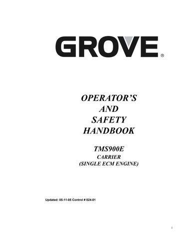
5.2.1 Carrier Lubrication
1.Engine Crankcase.
Lube Type - EO - 15W40
Lube Interval - Check fluid level every 10 hours or daily; drain, fill and replace filter every 250 hours.
Lube Amount - Capacity - 38.8 quarts (36.7 liters)
Application - Fill to full mark on dipstick.
2.Engine Cooling System.
Lube Type - AFC
Lube Interval - Check coolant level every 10 hours or daily; drain and refill cooling system every 2000 hours or 12 months.
Lube Amount - Capacity - 52 quarts (49.2 liters)
Application - Fill radiator to bottom of filler neck with AFC. Run engine through two (2) thermal cycles. Check coolant level and refill as required.
3.Transmission.
Lube Type - SGL-5
Lube Interval - Check fluid level and fill every 500 hours, 6 months or 9,000 miles (14,484 km); Drain, fill, and replace filter every 50,000 mi (80,450 km) or 2 years.
Lube Amount - Capacity - 20 quarts (19 liters) a. U-Joints.
Application - Through fill pipe to oil level mark on dipstick.
4.Pump Drive Shaft.
Lube Type - EP-MPG
Lube Interval - 250 hours or 3 months
Lube Amount - Until grease extrudes
Application - 2 grease fittings b. Spline.
Lube Type - EP-MPG
Lube Interval - 500 hours or 6 months
Lube Amount - Until grease extrudes
Application - 1 grease fitting
5.Clutch Throw-Out Bearing.
Lube Type - EP-MPG
Lube Interval - 250 hours or 3 months
Lube Amount - Until grease extrudes
Application - 1 grease fitting
6.Clutch Linkage.
Lube Type - EP-MPG
Lube Interval - 500 hours or 6 months
Lube Amount - Until grease extrudes
Application - 5 grease fittings
7.Transmission Shift U-Joints.
Lube Type - EP-MPG
Lube Interval - 500 hours or 6 months
Lube Amount - Until grease extrudes
Application - 3 grease fittings
8.Power Steering Gearbox.
Lube Type - EP-MPG
Lube Interval - 1000 hours or 12 months
Lube Amount - Until grease extrudes
Application - 1 grease fitting
9.Steering Relay Arms.
Lube Type - EP-MPG
Lube Interval - 250 hours or 3 months
Lube Amount - Until grease extrudes
Application - 2 grease fittings
10.Front Aluminum Wheel Pilots.
Lube Type - ASC
Lube Amount - Apply lubricant whenever wheels are removed for service
Do not lubricate the face of the wheel or the hub.
Lube Amount - Thoroughly coat the wheel pilot or hub pads.
Application - By brush; 4 places
11.Front Axle Hubs.
Lube Type - SSGL-5
Lube Interval - Check fluid level every 250 hours or 3 months and refill as necessary.
Lube Amount - 1.0 quart (0.95 liters)
Application - Fill to the oil level mark on the housing with the fill plug and the oil level mark horizontal.
12.Front Axle Tie Rod Ends.
Lube Type - EP-MPG
Lube Interval - 1000 hours or 12 months
Lube Amount - Until grease extrudes
Application - 4 grease fittings
13.Front Axle King Pins.
Lube Type - EP-MPG
Lube Interval - 1000 hours or 12 months
Lube Amount - Until grease extrudes
Application - 8 grease fittings
14.Front Axle Brake Slack Adjusters.
Lube Type - EP-MPG
Lube Interval - 1000 hours or 12 months
Lube Amount - Until grease extrudes
Application - 4 grease fittings
15.Front Axle Brake Camshafts.
Lube Type - EP-MPG
Lube Interval - 1000 hours or 12 months
Lube Amount - Until grease extrudes
Application - 4 grease fittings
16.Rear Aluminum Wheel Pilots.
Lube Type - ASC
Lube Interval - Whenever wheels are removed for service.
Lube Amount - Thoroughly coat the wheel pilot or hub pads.
Application - By brush; 8 places
17.Front Rear Axle Differential.
Lube Type - SSGL-5
Lube Interval - Check lubricant level every 250 hours or 3 months and refill as necessary. Drain and refill every 50,000 mi (80,450 km) or 2 years.
IF THE MAKEUP AMOUNT IS SUBSTANTIALLY MORE THAN 0.5 PINT (0.23 LITER) CHECK FOR LEAKS.
Change filter when changing gear oil.
Lube Amount - Capacity - 57 pints (27 liters) Normal makeup - less than 0.5 pint (0.23 liter)
Application - Fill to bottom of hole in the housing.
18.Rear Rear Axle Differential.
Lube Type - SSGL-5
Lube Interval - Check lubricant level every 250 hours or 3 months and refill as necessary. Drain and refill every 50,000 mi (80,450 km) or 2 years.
AXLE FLUID LEVELS SHALL BE ADJUSTED TO BOTTOM OF FILL PLUG THREADS. CHECK WITH CRANE ON LEVEL GROUND, AT ITS NORMAL RIDE HEIGHT; COLD OR ROOM TEMPERATURE OIL ONLY.
IF THE MAKEUP AMOUNT IS SUBSTANTIALLY MORE THAN 0.5 PINT (0.23 LITER) CHECK FOR LEAKS.
Any lubricant used in the field for either top-off or refill of the axles must be approved by Arvinmeritor. These lubricants are listed in Arvinmeritor (formerly Rockwell) lubricant specification 076P or Technical Bulletin TP-9539 available at www.arvinmeritor.com or by contacting Grove Crane Care.
Lube Amount - Capacity - 37 pints (17.5 liters) Normal makeup - less than 0.5 pint (0.23 liter)
Application - Fill to bottom of hole in the housing.
19.Rear Axle Brake Slack Adjusters.
Lube Type - EP-MPG
Lube Interval - 1000 hours or 12 months
Lube Amount - Until grease extrudes
Application - 4 grease fittings
20.Rear Axle Brake Camshafts.
Lube Type - EP-MPG
Lube Interval - 1000 hours or 12 months
Lube Amount - Until grease extrudes
Application - 4 grease fittings
21.Outrigger Beams.
Lube Type - EP-OGL
Lube Interval - 500 hours or 6 months
Lube Amount - Spray lubricant on bottom of outrigger beams
Application - Spray on
22.Jack Cylinder Support Tubes.
Lube Type - EP-OGL
Lube Interval - 500 hours or 6 months
Lube Amount - Spray lubricant on I.D. of jack cylinder support tubes before installing jack cylinders
Application - Spray on
23.Jack Cylinder Barrels.
Lube Type - EP-OGL
Lube Interval - 500 hours or 6 months
Lube Amount - Fully extend outriggers and spray lubricant onto cylinder barrels
Application - Spray on
24.Hydraulic Reservoir.
Lube Type - HYDO
Lube Interval - Check fluid level every 10 hours or daily, using sight gauge on side of tank, with boom down and all outrigger cylinders retracted; drain and refill as necessary. Replace oil every 2000 hours or 2 years; whichever interval occurs first.
After 2000 hours or 2 years of service, an oil sample should be taken and laboratory analyzed. If it continues to meet a minimum cleanliness level of ISO 19/17/14, the service interval can be increased to 3000 hours or 3 years.
Lube Amount - 134 gal. (507 liters), to FULL mark on sight gauge.
Application - Fill through breather/fill cap on top of tank. When tank is drained, clean the magnetic pipe plug.
Replace breather every 500 hours or 6 months whichever occurs first.
25.Hydraulic Filter.
Change the filter when the indicator is red. Check filter every 500 hours or 6 months, whichever interval occurs first
26.Fuel Filter.
Drain water trap every 10 hours or daily and change filter every 500 hours or 6 months.
27.Air Cleaner Filter.
Replace air cleaner filter element when indicator shows red (25” H2O).
28.Air Conditioner.
Check and fill. Refer to the applicable Air Conditioner Manual.
29.Driveline Slip.
Lube Type - EP-MPG
Lube Interval - 500 hours or 10,000 miles (16,093 km); whichever interval occurs first Lube Amount - Until grease extrudes Application - Two grease fittings
5.2.2 Superstructure Lubrication
40.Turntable Gearbox.
Lube Type - SSGL-5 Remove one valve to equalize the pressure before checking the swing gearbox oil level. This will keep the oil from pushing out.
Lube Interval - Check and fill every 50 hours. Drain and fill every 1000hours or 12 months thereafter.
Lube Amount -
SOM Gearbox - Capacity - 5.28 quarts (5 liters)
Application - Fill mark on dipstick
41.Turntable Gear Brake
Superstructure Lubrication Diagram
Lube Type - Hydraulic oil ATF66M Avia fluid
Lube Interval - Check and fill every 50 hours. Drain and fill every 1000 hours or 12 months thereafter.
Lube Amount - Capacity 2.1 pints (1.0 liters)
Application - Fill until oil level is at top of sight gauge.
42.Turntable Gear and Drive Pinion.
Lube Type - EP-OGL
Lube Interval - 500 hours or 6 months
Lube Amount - Coat all teeth
Application - Spray on
43.Turntable Bearing.
Lube Type - EP-MPG
Lube Interval - 500 hours or 6 months
Lube Amount - Coat all teeth
Application - Brush on.
44.Main Hoist - Transmission.
Lube Type - SSGL-5
Lube Interval - Drain and fill every 1000 hours or 12 months
Lube Amount - Capacity - 9.5 quarts (9.0 liters)
Application - Through fill pipe to oil level mark on sight gauge.
45.Main Hoist - Brake.
Lube Type - SSGL-5
Lube Interval - Drain and fill every 1000 hours or 12 months
Lube Amount - Capacity - 1.1 quarts (1.0 liter)
Application - Fill until level with the check plug opening.
46.Auxiliary Hoist - Transmission (Optional).
Lube Type - SSGL-5
Lube Interval - Drain and fill every 1000 hours or 12 months
Lube Amount - Capacity - 9.5 quarts (9.0 liters)
Application - Through fill pipe to oil level mark on sight gauge.
47.Auxiliary Hoist - Brake (Optional).
Lube Type - SSGL-5
Lube Interval - Drain and fill every 1000 hours or 12 months
Lube Amount - Capacity - 1.1 quarts (1.0 liter)
Application - Fill until level with the check plug opening.
48.Auxiliary Hoist Gears - (Optional).
Lube Type - EP-MPG
Lube Interval - 50 hours or 1 week
Lube Amount - Until grease extrudes
Application - 1 grease fitting
49.Counterweight Hoist Unit.
Lube Type - EP-MPG
Lube Interval - 100 hours or monthly
Lube Amount - Until grease extrudes
Application - 6 grease fittings; 3 on each side
50.Central Lubrication System.
Lube Type - EP-MPG
Lube Interval - 50 hours or 1 week
Application - Fill grease container until oil level is at the “max” mark.
Lift Cylinder Pin.
Lube Type - EP-MPG
Lube Interval - 50 hours or weekly
Lube Amount - Fill grease container until oil level is at the “MAX” mark.
Application - 1 grease fitting
Boom Pivot Pin.
Lube Type - EP-MPG
Lube Interval - 50 hours or weekly
Lube Amount - Fill grease container until oil level is at the “MAX” mark.
Application - 4 grease fittings
Main Hoist - Gears.
Lube Type - EP-MPG
Lube Interval - 50 hours or weekly
Lube Amount - Fill grease container until oil level is at the “MAX” mark.
Application - 1 grease fitting
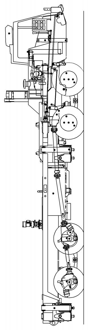
5.2.3 Boom, Boom Extension, and Boom Accessories Lubrication
FOR ACCESS THROUGH HOLES WHEN LUBRICATING WEAR PADS, MAKE SURE BOOM IS EXTENDED.
70.Upper Wear Pads - Inner Mid.
Lube Type - EP-MPG
Lube Interval - 500 hours or 6 months
Lube Amount - Until grease extrudes
Application - 2 grease fittings; extend boom for entry through access hole in base section.
71. Upper Wear Pads - Center Mid.
Lube Type - EP-MPG
Lube Interval - 500 hours or 6 months
Lube Amount - Until grease extrudes
Application - 2 grease fittings; extend boom for entry through access hole in inner mid section.
72. Upper Wear Pads - Outer Mid.
Lube Type - EP-MPG
Lube Interval - 500 hours or 6 months
Lube Amount - Until grease extrudes
Application - 2 grease fittings; extend boom for entry through access hole in center mid section.
73. Upper Wear Pads - Fly.
Lube Type - EP-MPG
Lube Interval - 500 hours or 6 months
Lube Amount - Until grease extrudes
Application - 2 grease fittings; extend boom for entry through access hole in outer mid section.
74.Telescopic Slide Faces.
Lube Type - EP-MPG
Lube Interval - 500 hours or 6 months
Lube Amount - Thoroughly coat all areas the wear pads move on.
Application - By brush; 8 places
Should boom chatter or rubbing noises in the boom occur, it will be necessary to lubricate the telescopic slide faces. By adding an extension adapter to a grease gun, the wear pads and wear areas can be reached through the lubrication access holes in the side of the boom and through the access hole in the boom nose between the sheaves.
75.Derricking Cylinder Pivot Pin.
Lube Type - EP-MPG
Lube Interval - 100 hours or monthly
Lube Amount - Until grease extrudes
Application - 2 grease fittings
76.10 M Section Pivot Pin.
Lube Type - EP-MPG
Lube Interval - 100 hours or monthly
Lube Amount - Until grease extrudes
Application - 2 grease fittings
77.Hookblock Sheaves.
Lube Type - EP-MPG
Lube Interval - 250 hours or 3 months
Lube Amount - Until grease extrudes
Application - 1 grease fitting
78.Hookblock Swivel Bearing.
Lube Type - EP-MPG
Lube Interval - 250 hours or 3 months
Lube Amount - Until grease extrudes
Application - 1 grease fitting
79.Headache Ball - Swivel Top.
Lube Type - EP-MPG
Lube Interval - 250 hours or 3 months
Lube Amount - Until grease extrudes
Application - 1 grease fitting
80.Boom Extension Sheave.
Lube Type - EP-MPG
Lube Interval - 250 hours or 3 months
Lube Amount - Until grease extrudes Application - 2 grease fitting
81.Mast Sheave.
Lube Type - EP-MPG
Lube Interval - 500 hours or 12 months
Lube Amount - Until grease extrudes
Application - 2 grease fitting
When lubricating the Tele Boom Locking Pins (items 82 through 85), refer to the Boom Locking Pin Lubrication Procedure.
82.Tele 4 Boom Locking Pin.
Lube Type - High-Lube SW 2 Spray-On Grease
Lube Interval - 250 hours or 3 months
Lube Amount - Thoroughly lubricate pin Application - Spray on
83.Tele 3 Boom Locking Pin.
Lube Type - High-Lube SW 2 Spray-On Grease
Lube Interval - 250 hours or 3 months
Lube Amount - Thoroughly lubricate pin
Application - Spray on
84.Tele 2 Boom Locking Pin.
Lube Type - High-Lube SW 2 Spray-On Grease
Lube Interval - 250 hours or 3 months
Lube Amount - Thoroughly lubricate pin
Application - Spray on
85.Tele 1 Boom Locking Pin.
Lube Type - High-Lube SW 2 Spray-On Grease
Lube Interval - 250 hours or 3 months
Lube Amount - Thoroughly lubricate pin
Application - Spray on
5.2.4 Boom Locking Pins Lubrication Procedure
The following items used in this procedure can be ordered from Manitowoc CraneCARE:
•Beechem High-Lube SW2 Spray Oil - Part Number 02313314
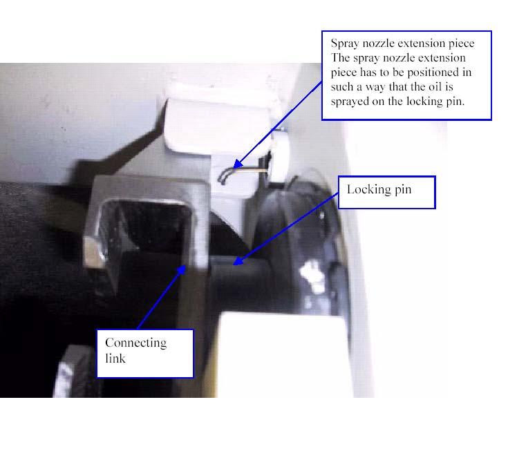
•Spray Nozzle Extension Piece - Part Number 03323923
Preparing The Crane Due to a risk of overturning the crane when the boom is in the horizontal position, the following guidelines must be followed:
OVERRIDE THE SLI ONLY WHEN YOU ARE PROMPTED TO DO SO IN THE ATTACHED PROCEDURE AND DO NOT EXTEND THE MAIN BOOM MORE THAN INDICATED.
Before lowering or extending the boom, the following conditions must be met:
1.Park the crane on a flat, level surface.
2.Configure the crane with full outrigger span and at least 4.0 ton of counterweight installed.
3.Enter the SLI rigging code for the current rigging mode of the crane.
4.Fully retract all boom telescope sections.
5.Lower the main boom to the horizontal position.
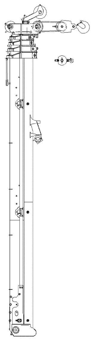
Lubricating Tele Locking Pin 4
1.Set the boom angle to horizontal (0 degree) and unlock the locking pins of tele 4. Gain access to the left hand locking pins behind the superstructure cab.
2.Turn the curved end of the spray nozzle extension piece horizontally to the side (refer to figure titled, Tele 4 Left Hand Side Pin) so that it is pointing rearwards and insert it through the access hole (situated in front of the step on the boom section) until it contacts the connecting link, then retract the spray nozzle extension piece by about 1 to 2 cm (refer to figure titled, Spray Nozzle Extension - Tele 4 Pin). The nozzle is now in position to be able to lubricate the pin.
3.Apply 2 shots of lubricating oil onto the locking pin and then withdraw the spray nozzle extension piece from inside the access hole. Repeat the process for the right hand locking pin.
4.Unlock and lock the pin several times to enable the oil to spread around the pin and into the
Lubricating Tele Locking Pin 3
1.Set the boom angle to horizontal (0° degree) and unlock the locking pins of tele 3. Gain access to the left hand locking pins behind the superstructure cab.
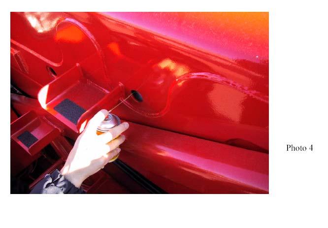
2.Turn the curved end of the spray nozzle extension piece vertically down and insert it through the access hole (situated behind the step on the boom section) until it contacts the connecting link, and then retract the spray nozzle extension piece by about 1 to 2 cm (refer to figure titled, Tele 3 Left Hand Side Pin). The nozzle is now in position to be able to lubricate the pin.
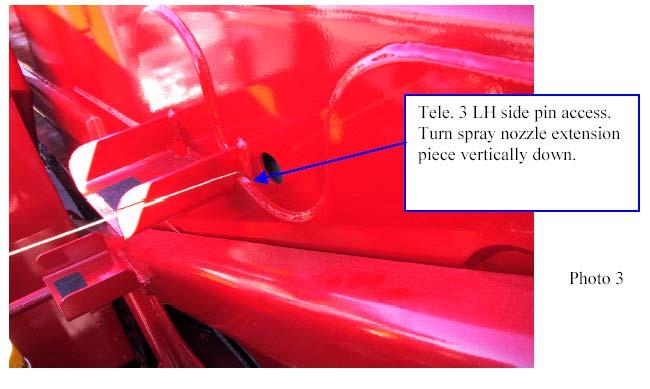
3.Apply 2 shots of lubricating oil onto the locking pin and then withdraw the spray nozzle extension piece from inside the access hole (refer to figure titled, Spray Nozzle ExtensionTele 3 Pin). Repeat process for the right hand locking pin.
4.Unlock and lock the pin several times to enable the oil to spread around the pin and into the bore.
Lubricating Tele Locking Pin 1 and 2
1.Raise the boom until the left hand side access holes for tele 1 lock pin and tele 2 lock pin are accessible behind the cab. Unlock the locking pins of tele 2.
2.Turn the curved end of the spray nozzle extension piece vertically down and insert it through the access hole (situated directly behind tele 3 access hole) until it contacts the connecting link, then retract the spray nozzle extension piece by about 1 to 2 cm. The nozzle is now in position to be able to lubricate the pin.
Ensure that the end of the extension piece is at right angles to the boom top plate. Apply 2 shots of lubricating oil onto the locking pin and then withdraw the spray nozzle extension piece from inside the access hole. Repeat process for the right hand locking pin.
3.Unlock and lock the pin several times to enable the oil to spread around the pin and into the bore. Repeat this procedure for tele 1 (through the access hole situated directly behind tele 2).
4.Lubricate all of the right hand side locking pins using the same procedure. If there is a swingaway mounted on the side of the boom, then it must either be removed or erected on the boom head following the correct procedure in this manual.
5.2.5 Wire Rope Lubrication
Wire rope is lubricated during manufacturing so that the strands, and individual wires in strands, may move as the rope moves and bends. A wire rope cannot be lubricated sufficiently during manufacture to last its entire life. Therefore, new lubricant must be added periodically throughout the life of a rope to replace factory lubricant which is used or lost. For more detailed information concerning the lubrication and inspection of wire rope, refer to HOIST ROPE in Section 8 - DESCRIPTION OF MAINTENANCE ON THE SUPERSTRUCTURE in the Service Manual.