4 minute read
DANGER


ANUNTRAINEDOPERATORSUBJECTSHIMSELF ANDOTHERSTODEATHORSERIOUSINJURY.
YOUMUSTNOTOPERATETHISMACHINEUNLESS:
•YOUHAVEBEENTRAINEDINTHESAFEOPERATIONOFTHISMACHINE;
• YOUREAD,UNDERSTANDANDFOLLOWTHESAFETYANDOPERATING RECOMMENDATIONSCONTAINEDINTHEMANUFACTURER’SMANUALS,YOUR EMPLOYER’SWORKRULESANDAPPLICABLEGOVERNMENTREGULATIONS
•YOUARESURETHEMACHINEISOPERATINGPROPERLYANDHASBEEN INSPECTEDANDMAINTAINEDINACCORDANCEWITHTHE MANUFACTURER’SMANUAL;
•YOUARESURETHATALLSAFETYSIGNS,GUARDSANDOTHERSAFETY FEATURESAREINPLACEANDINPROPERCONDITION.
NOTICE TO OWNER/USER
Should this crane become involved in an accident, please contact your local Grove distributor immediately and relate details of the incident so he can notify Grove Worldwide. If the distributor is unknown and/or cannot be reached, please contact:
Grove Worldwide Product Safety & Reliability
1565 East Buchanan Trail
Shady Grove, PA 17256-0021
Telephone: 888-777-3378 (888-PSR-DEPT)
Facsimile: 717-593-5074
Email: psafety@groveworldwide.com
Foreword
This handbook has been compiled to assist you in properly operating and maintaining your Grove Crane.
Before placing the crane in service, take time to thoroughly familiarize yourself with the contents of this manual. After all sections have been read and understood, retain the manual for future reference in a readily accessible location.
The Grove Crane has been designed for maximum performance with minimum maintenance. With proper care, years of trouble-free service can be expected.
Constant improvement and engineering progress makes it necessary that we reserve the right to make specification and equipment changes without notice.
Grove Worldwide and our Dealer Network want to ensure your satisfaction with our products and customer support. Your local dealer is the best equipped and most knowledgeable to assist you for parts, service and warranty issues. They have the facilities, parts, factory trained personnel, and the information to assist you in a timely manner. We request that you first contact them for assistance. If you feel you need factory assistance, please ask the dealer’s service management to coordinate the contact on your behalf.
Engine operating procedures and routine maintenance procedures are supplied in a separate manual with each crane, and should be referred to for detailed information.
Information in this manual does not replace federal, state, or local regulations, safety codes, or insurance requirements.
Manitowoc/Grove remains committed to providing reliable products that enable users and operators to safely lift and position loads. Manitowoc/Grove has been an industry leader in the incorporation of operational aids into the design of its cranes. Federal law requires that cranes be properly maintained and kept in good working condition. The manuals that Manitowoc/ Grove provides that are specific for each crane and the manufacturer’s manuals for the operational aids shall be followed. If an operational aid should fail to work properly, the crane user or owner must assure that repair or recalibration is accomplished as soon as is reasonably possible.If immediate repair or recalibration of an operational aid is not possible and there are exceptional circumstances which justify continued short-term use of the crane when operational aids are inoperative or malfunctioning, the following requirements shall apply for continued use or shutdown of the crane:
1.Steps shall be taken to schedule repairs and recalibration immediately. The operational aids shall be put back into service as soon as replacement parts, if required, are available and the repairs and recalibration can be carried out. Every reasonable effort must be made to expedite repairs and recalibration.
2.When a load indicator, rated capacity indicator, or rated capacity limiter is inoperative or malfunctioning, the designated person responsible for supervising the lifting operations shall establish procedures for determining load weights and shall ascertain that the weight of the load does not exceed the crane ratings at the radius where the load is to be handled.
3.When a boom angle or radius indicator is inoperative or malfunctioning, the radius or boom angle shall be determined by measurement.
4.When an anti-block device, two-blocking damage prevention or two-block warning device is inoperative or malfunctioning, the designated person responsible for supervising the lifting operations shall establish procedures, such as assigning an additional signal person to furnish equivalent protection. This does not apply when lifting personnel in loadline supported personnel platforms. Personnel shall not be lifted when anti-two block devices are not functioning properly.
5.When a boom length indicator is inoperative or malfunctioning, the designated person responsible for supervising the lifting operations shall establish the boom lengths at which the lift will be made by actual measurements or marking on the boom.
6.When a level indicator is inoperative or malfunctioning, other means shall be sued to level the crane.
The following definitions and symbols are used in this manual to highlight important information.
THIS SYMBOL IS USED TO EMPHASIZE THAT IF AN OPERATION, PROCEDURE, OR PRACTICE IS NOT FOLLOWED EXACTLY, DEATH OR INJURY TO PERSONNEL MAY RESULT.
THIS SYMBOL IS USED TO EMPHASIZE THAT IF AN OPERATION, PROCEDURE, OR PRACTICE IS NOT FOLLOWED EXACTLY, EQUIPMENT DAMAGE MAY RESULT.
THIS SYMBOL ALERTS YOU TO SITUATIONS WHERE YOU ARE IN DANGER OF RECEIVING AN ELECTRIC SHOCK.
This symbol is used to emphasize an important procedure or condition.
List Of Figures
List Of Charts
1.1 GENERAL
This handbook provides information for the operator of the TMS900E Manitowoc/Grove Crane.
The mobile crane carrier incorporates an all welded steel frame. The 8 x 4 x 4 carrier utilizes two drive axles and two steer axles. Axle steering is provided by a power steering pump, and power steering gear. The engine is mounted in the front of the carrier and provides power through an 11 speed forward and 3 speed reverse manual transmission.
Hydraulic, two-stage double box telescopic beam with inverted stabilizer (jack) cylinder outriggers are integral with the carrier frame. The outriggers are utilized in three positions; fully extended, intermediate (50%) extended, and fully retracted. The carrier is also equipped with a center front stabilizer with a permanently stowed pad.
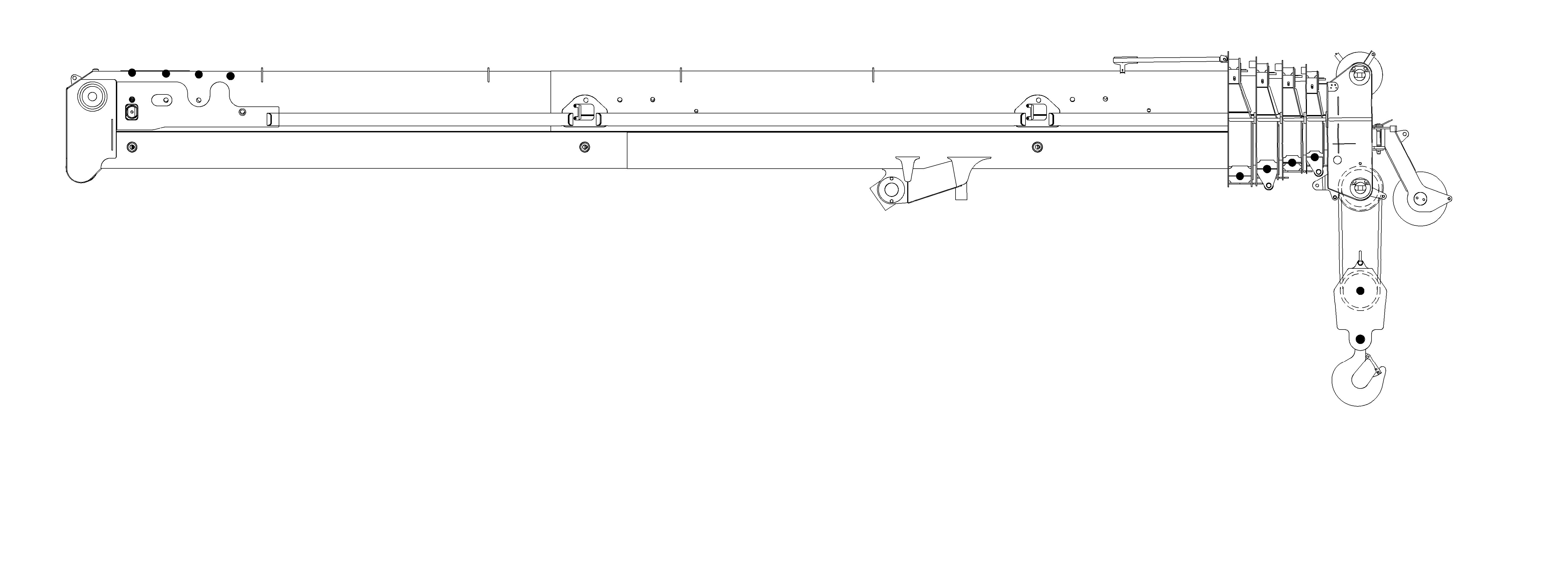
The superstructure is capable of 360° rotation in either direction. All crane functions are controlled from the fully enclosed cab. The crane is equipped with a 36.7 to 141.7 ft (11.2 m to 43.2 m) five section boom.
Lifting is provided by a main and auxiliary hoist. Swingaway hydraulically offsettable and manually offsettable boom extensions are available.
HThroughout this manual, reference is made to left, right, front, and rear when describing locations. These reference locations are to be considered as those viewed from the operator’s seat with the superstructure facing forward over the front of the carrier frame.
Auxiliary Hoist
Main Hoist
Boom Pivot
Superstructure Cab
Counterweight Deck Stowage
Lift Cylinder
Counterweight
Rear Outrigger Jack Cylinder
Rear Tandem Axles

Fuel Tank
Front Outrigger Jack Cylinder
Engine Compartment
Carrier Cab
Center Front Stabilizer Jack Cylinder
Steering Axles
6165-1
Basic Nomenclature (Sheet 1 of 3)
Basic Nomenclature (Sheet 2 of 3)