47 minute read
TMS700E OPERATORS MANUALOPERATING CONTROLS AND PROCEDURES


ItemDescription
25Engine Stop Indicator
26Front Stabilizer Overloaded Indicator
27Tachometer
28Hourmeter
29Gauge Cluster (Fuel, Temperature, Oil, Volts)
30LMI Panel
31Hand Throttle Switch
32Ignition Switch
33Air Conditioning Control Switch (Optional)
34Heat Control Knob
3512 VDC Accessory Outlet
36Fan Switch
37Crane Function Power Switch
38Windshield Wiper/Washer Switch
39Panel Light Control Dimmer
40Work Lights Switch
41Boom Lights Switch (Optional)
42Positive Swing Lock Release Lever
43Positive Swing Lock Foot Pedal
44Outrigger Extension/Retraction Switch
45Center Front Stabilizer Control Switch
46Outrigger Selector Switches
47Wait to Start Indicator
48Engine Warning Indicator
49Regen Exhaust Filter Indicator
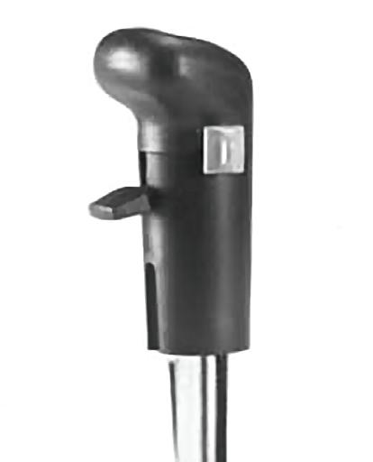
Hoist Rotation Indicators
The hoist rotation indicators (“thumb thumpers”) are located on top of each hoist control lever. The indicators are electronically driven by a signal from an electronic transmitter and sensor attached to each hoist. A pulsating signal is sensed by the operator’s thumb during hoist operation.
Crane Function Power Switch
The CRANE FUNCTION power switch (37) is located on the right overhead console. This two-position (ON/OFF) rocker switch permits the operator to disconnect power from the crane functions controlled by the hydraulic remote controllers on the armrests. Po sitioning the s witch to OFF prevents inadvertent operation of functions due to bumping the controllers while roading or any other operation. With the switch in the OFF position, operation of hydraulic boost and high speed hoist is also prevented. When the switch is in the ON position, the red LED square in the switch will light.
Hydraulic Boost Switch
NOTE: The hydraulic boost switch must be positioned to LOW to function the outrigger circuits
The hydraulic boost control switch (11) is located on the right arm rest. This two position switch is used to control the high speed boost selector valve. With the switch in the HI position, the solenoid valve is energized. The solenoid valve stops flow of oil from Pump No. 1 (Section 2) to the integrated outrigger selector valve. The poppet check valve opens to combine this flow of oil with the output from Pump No. 1 (Section 1). Hydraulic boost will not function unless the CRANE FUNCTION switch is in the ON position. With the switch in the HI position, the amber LED square in the switch will light.
Outrigger Control Box
NOTE: The park brake in the carrier cab must be set before the outrigger controls will operate.
The outrigger control box contains the switches that are used to control the outrigger beams, stabilizers, and center front stabilizer. The box is a hand held unit that is stored in a pocket at the left front of the superstructure cab. The parking brake must be set before the outrigger controls can be operated.
There are four outrigger selector switches on the top of the control box and one extend/retract switch on the side of the control box. To extend or retract an outrigger component, first select the component with the outrigger selector switch, then select extend or retract with the appropriate outrigger extend/retract switch.
A CENTER FRONT STABILIZER switch is also located on the top of the outrigger control box. To extend or retract the center front stabilizer, pre ss the Center Front Stabilizer switch and then energize the related extend/retract switch.
NOTE: The center front stabilizer will retract any time any one of the main stabilizers are retracted.
Front Stabilizer Overloaded Indicator
The FRONT STABILIZER OVERLOADED indicator (26) is located on the LED alert panel at the top of the front console. The indicator is a red light that will light when the pressure switch in the front stabilizer circuit senses overpressurization indicating an overload condition. In addition to the indicator light, a buzzer will sound.
Bubble Level Indicator
The bubble level indicator (5) is located at the bottom of the front console. The indicator provides the operator with a visual indication for determining the levelness of the machine.
Swing Brake Control Switch
The SWING BRAKE control switch (17) is located on the left armrest. This two-position rocker switch (ON/OFF) is used to control a hydraulic valve that directs a regulated flow of pressure to and from the swing brake. Positioning the switch to ON will apply the swing brake and positioning the switch to OFF will release the swing brake. When the switch is in the ON position, the square amber LED in the switch is lit.
Swing Brake Pedal
The swing brake pedal (22) is located on the left side of the cab floor. The swing brake pedal is used to actuate the swing brake to slow or stop swing motion. Braking is proportional to pedal depression. With the pedal not depressed and the swing brake control valve disengaged, hydraulic pressure is applied to the brake, overcoming spring pressure and releasing the brake. Depressing the pedal actuates a swing power brake valve to apply pressure to the brake assembly. This pressure aids the spring pressure to overcome the hydraulic pressure being applied to the brake release circuit and applies the spring brake according to the pressure from the swing power brake valve.
Pin Swing Lock Control (Pin Type)
The pin swing lock control handle (6) is located on the right side of the cab. The purpose of the pin swing lock is to lock the superstructure in position directly over the front or over the rear. When the control handle is pushed down and the superstructure is directly over the front or rear, the swing lock pin drops into a socket on the carrier frame, locking the superstructure in place. When the control handle is pulled up, the pin is pulled out of the socket, unlocking the superstructure.
Swing Lock Control (Positive Lock Type)
The swing lock control pedal (24) is located on the left side of the cab floor. The purpose of the swing lock is to secure the superstructure in any position. When the control pedal is up, the swing lock is disengaged and swing can be accomplished. Pushing down on the control pedal engages the swing lock.
Accessory Controls and Indicators
Panel Light Control
The panel light (PANEL DIM) control (39) is located on the right overhead console. Rotate the control knob to turn the lights on and control the brightness of the gauge lights.
Work Lights Switch
The WORK lights switch (40) is a two position ON/OFF rocker switch which is located on the right overhead console and controls the crane’s work lights mounted on the top front of the superstructure cab. When the switch is in the ON position, the square amber LED in the switch is lit.
Boom Lights Switch (Optional)
The BOOM lights switch (41) is a two position ON/OFF rocker switch located on the overhead panel. The switch controls the flood lights located on the boom base section. When the switch is in the ON position, the square amber LED in the switch is lit.
Cab Circulating Fan
The cab circulating fan (23) is located on a mounting bracket above the left window frame. A swivel allows the fan to be positioned in any direction and a high-off-low switch on the base controls the fan.
Cab Dome Light
The cab dome light (12) is located on the right rear corner of the cab roof and provides illumination of the cab. The light is controlled by a on/off switch on the light.
Fire Extinguisher
The fire extinguisher (15) is located at the left rear side of the cab. The fire extinguisher is a BC rated dry type fire extinguisher for emergency use.
Windshield Wiper/Washer Switch
The WINDSHIELD wiper/washer switch (38) is located on the overhead console. The switch is a three position rotary switch (off-low-high) that controls the windshield wiper. The low and high positions run the wiper at low and high speeds and the off positions turns off the wiper and parks the wiper blade. Pushing the switch sprays washer fluid on the windshield.
Skylight Wiper
The electrically-operated skylight wiper (21) is installed to remove moisture from the skylight. The wiper is located on the left side of the skylight frame.The skylight wiper is controlled by an on/off switch on the wiper motor.
Heat Control Knob
The HEAT control knob (34) is located on the front console. The knob is a push-pull control that positions a flow diverter valve in the hot water heater supply line. Pull out on the knob (PULL ON) to allow hot water to flow through the heater coil and push in on the knob (PUSH OFF) to shut off the flow of hot water to the coil.
Fan Switch
The FAN control switch (36) is located on the left side of the front console. The switch is a four-position rotary switch (OFF, LOW, MED, HI) that controls operation of the blower to circulate heated or cool air throughout the cab.
Air Conditioner Control Switch (Optional)
The air conditioner (AIR COND) control switch (33) is located on the right side of the front console. The switch is a twoposition rocker switch (OFF, ON) that controls the operation of the optional air conditioning system in conjunction with the FAN switch. When the switch is in the ON position, the square amber LED on the switch is lit.
Beacon Light (Optional)
The beacon light (14) is located on the left rear corner of the cab roof. It is operational anytime the ignition switch is in the ACC or RUN position.
12 VDC Accessory Outlet
The 12 VOLT accessory outlet (35) is located at the bottom of the front console. It provides an outlet for the operator to plug in a 12 vdc accessory. It is protected by a 10 amp fuse.
Circuit Breaker Panel
The fuse panel (13) is located under the cover panel on the back wall of the cab behind the seat. It contains fuses that protect the various electrical components of the superstructure.
Operating Procedures
Breaking In A New Carrier
Your new Grove Manitowoc carrier has been thoroughly tested, adjusted, lubricated, and inspected prior to delivery. For detailed engine break-in, refer to the applicable engine manual.
The guidelines below will aid in getting a long service life out of the crane.
1. Operate as much as possible in the half to threequarters throttle or load range.
2. Avoid long periods of operation with the engine at idle or continuous maximum horsepower levels.
3. Observe instruments often and shut down at the first indication of an abnormal reading.
4. Operate to a power requirement that allows acceleration to governed speed when conditions require more power.
5. Check all components frequently for proper operation, unusual noises, and excessive heating.
6. Check the engine oil and coolant levels frequently. These guidelines should not be considered limitations but rather as a guide for familiarization of the machine and development of good operating habits.
Pre-Starting Checks
A complete walk-around visual inspection of the crane should always be made with special attention to structural damage, loose equipment, leaks, or other conditions that would require immediate correction for safe operation. Refer to Section 6 - Maintenance Checklist. The following checklist items are suggested to ensure the crane is prepared for starting the day’s work.
Fuel Supply
Fill the fuel tank and ensure the cap is on tight.
Engine Oil
Caution
Do not overfill.
Check the oil level in the crankcase and fill to the FULL mark on the dipstick. Do not overfill.
Engine Coolant
Check the coolant level in the radiator and fill to the proper level. Do not overfill and ensure the radiator cap is secure.
Danger
Do not loosen radiator cap on a hot engine. Steam or hot coolant will cause severe burns.
Batteries
Check the state-of-charge indicator if applicable with maintenance free batteries or check each cell for the correct fluid level if equipped with standard or low maintenance batteries. Use only clean distilled water and do not overfill. On all types of batteries, make sure the cables and clamps are tight and not corroded.
Hydraulic Reservoir and Filter
Check the hydraulic level sigh t gauge and filter condition indicator on the hydraulic tank. Hydraulic fluid should be at normal operating temperature and the boom and outriggers in a retracted position.
Check breather for cleanliness and security.
Wire Rope
Inspect the wire rope in accordance with applicable Federal Regulations. Sheaves, guards, guides, drums, flanges, and any other surfaces that come in contact with the rope should be inspected for any condition that could cause possible damage to the rope.
Hook Block and Headache Ball
Inspect for nicks, gouges, cracks, and evidence of any other damage. Replace a hook that has cracks or shows evidence of excessive deformation of the hook opening (including twist). Be sure the safety latch is free and aligned.
Swingaway Extension
Danger
Engage boom extension stop block to keep swingaway and boom nose attach fittings from hitting each other when boom is retracted. Failure to do so can result in damage to the boom and possible injury or death to personnel.
The boom extension stop block must be engaged to keep the swingaway and boom nose attach fittings from hitting each other, when the boom is fully retracted and the swingaway is properly stowed.
Seats and Mirrors
Adjust seat and mirrors for clear vision and safe driving.
Seat Belts
Seat Belt Maintenance
Seat belt assemblies are maintenance-free; however, they should be periodically inspected to ensure that they are not damaged and are in proper operating condition, especially if they have been subjected to severe stress.
Cleaning Seat Belt Webbing
Wash the seat belt webbing with any mild soap or detergent. Do not use commercial solvents. Also, bleaching or redyeing the webbing is not recommended because of possible loss of webbing strength.
Signal and Running Lights
Check all signal and running lights for proper operation. Replace burned out lamps with those of the same number, or equivalent.
Service and Parking Brakes
Check for proper operation.
Tires
Check the pressure and condition of all tires before traveling.
NOTE: For tire inflation pressures, refer to the Tire Inflation Decal on the crane.
Wheels
Maintain proper torque on wheel lugs and check for proper wheel mounting. If equipped with steel or aluminum wheels, the wheels should be retorqued 80 to 160 km (50 to 100 miles) after initial installation or after any time the tires and wheels are removed. Doing this will reseat the lug nuts. Recheck the lug nuts for proper torque every (800km) 500 miles thereafter.
Safety Equipment
Check all lights, windshield wipers, washers, washer liquid supply, horn, instruments, signaling devices, etc.
Daily Lubrication
Ensure all components requiring daily lubrication have been serviced. (Refer to Section 5, Lubrication).
Cold Weather Operation
The following recommendations are for operating Grove cranes in very low (i.e. freezing) temperatures.
Use particular care to ensure that cranes being operated in very cold temperatures are operated and maintained in accordance with the procedures as provided by Grove Manitowoc Crane Group. Cranes should have appropriate hydraulic oil, lubricants, and other auxiliary items required for operation in sub-zero temp eratures. Individual crane functions should be operated to ensure they are sufficiently warmed prior to performing a lift.
Operation of cranes at full rated capacities in temperatures between 0°C and -40°C (+32°F and -40°F) or lower shall be accomplished only by competent operators who possess the skill, experience, and dexterity to ensure smooth operation. Shock loading shall be avoided. For crane operation below40°C (-40°F), capacities shall be derated 3.6% for each °C below -40°C and 2% for each °F below -40 °F of the rated load shown on the capacity charts.
Operation Below -40°C
For crane operation below -40°C, capacities shall be derated 3.67% of the capacities shown on the load chart for each degree (1°C) below -40°C.
Operation Below -40°F
For crane operation below -40°F, capacities shall be derated 2.0% of the capacities shown on the load chart for each degree (1°F) below -40°F.
Engine Operation
Start-up and shutdown procedures for most diesel engines are generally the same. Therefore, the following procedures can be applied, except where specific differences are noted. (Refer to the applicable engine manufacturer’s manual for detailed procedures).
Start-Up Procedure
Make an under-the-hood inspection for fuel, oil, and coolant leaks, worn drive belts, and trash build-up.
Danger
Diesel engine exhaust can be harmful to your health. Only operate the engine in a well ventilated area or vent exhaust outside.
Caution
Never crank engine for more than 30 seconds during an attempted start. If engine does not start after 30 seconds, allow starter motor to cool for about two minutes before attempting another start.
Caution
If engine does not start after four attempts, correct malfunction before attempting another start.
Use the correct grade of oil for the prevailing temperature in the crankcase to prevent hard cranking. Diesel fuel should have a pour point of 5°C (10°F) less than the lowest expected temperature. In case of an emergency, white kerosene can be added to the fuel to bring the pour point down to the required temperature. This will prevent clogging of filters and small passages by wax crystals. The addition of kerosene is NOT recommended for general use.
Warm Engine
The ENGINE WARNING and ENGINE STOP indicators will light and go off in sequence after about two seconds (as a check) when the key is first turned on. If an indicator comes on after initial start-up, there is a problem that needs to be corrected. With the ignition key on, but engine not running, place the engine diagnostics test switch at ON for code retrieval and check the engine manufacture’s service manual for code identification.
1. Place the hydraulic switch at DISENGAGE.
2. Ensure the parking brake is set and position the transmission in neutral.
NOTE: The engine will not crank unless the transmission shift is in neutral.
3. Turn the IGNITION switch to START (2) and release immediately when the engine starts. Do not push or hold the throttle down. The ECM will automatically provide the proper amount of fuel to start the engine.
4. Immediately check the engine instruments for proper indication after starting. Shut down the engine if the oil pressure gauge does not reach the proper reading within 15 seconds.
Danger
Both air system pressures must be in the normal operating range prior to disengaging the park brake.
Caution
If oil pressure and/or temperature indicator(s) do not display the proper readings, shut down engine and correct malfunction.
5. Allow the engine to warm up for about five minutes before applying a load. Do not race the engine for a faster warm up.
Cold Engine
Danger
Wear proper eye protection when replacing starting fluid containers. Starting fluid can cause blindness or severe eye damage and breathing problems.
Caution
Always start a cold engine from the carrier cab (with pump disconnected).
The ENGINE WARNING and ENGINE STOP indicators will light and go off in sequence after about two seconds (as a check) when the key is first turned on. If an indicator comes on after initial start-up, there is a problem that needs to be corrected. Place the engine diagnostics test switch at ON for code retrieval and check the engine manufacture’s service manual for code identification.
The engine is equipped with an automatic cold starting system that provides a metered flow of starting fluid to the engine when the engine determines this is necessary. An engine block heater is also provided. It is recommended that no other type of cold starting aid be used with this engine. If starting fluid runs out, replace the empty starting fluid container with a full container.
Caution
The optional engine cold start system operates automatically when the engine temperature is at or below a preset temperature. If the engine does not start immediately, avoid overloading the air box with highly volatile fluid which could result in a minor explosion.
1. Place the hydraulic pump switch at DISENGAGE.
2. Ensure the parking brake is set and position the transmission in neutral.
NOTE: The engine will not crank unless the transmission shift is in neutral.
3. Turn the ignition switch to START (2) and release immediately when the engine starts. Do not push or hold the throttle down. The ECM will automatically provide the proper amount of fuel to start the engine.
4. Immediately check the engine instruments for proper indication after starting. Shut down the engine if the oil pressure gauge does not reach the proper reading within 15 seconds.
Danger
Both air system pressures must be in the normal operating range prior to disengaging the park brake.
Caution
If oil pressure and/or temperature indicator(s) do not display the proper readings, shut down engine and correct malfunction.
5. Allow the engine to warm up for about five minutes before applying a load. Do not race the engine for a faster warm up.
Idling The Engine
Idling the engine unnecessarily for long periods of time wastes fuel and fouls injector nozzles. Unburned fuel causes carbon formation; oil dilution; formation of lacquer or gummy deposits on the valves, pistons and rings; and rapid accumulation of sludge in the engine.
NOTE: When prolonged engine idling is necessary, maintain at least 800 rpm.
Racing The Engine
DO NOT race the engine du ring the warm-up period or operate the engine beyond governed speed (as might occur in downhill operation or dow nshifting). Engine bearings, pistons, and valves may be damaged if these precautions are not taken.
Shutdown Procedure
1. Allow the engine to run at fast idle speed for about five minutes to avoid high internal heat rise and allow for heat dissipation.
2. Position the ignition switch to OFF.
3. Drain the fuel filter-water separator.
General Crane Operation Pump Drive
The main three section hydraulic pump is driven by an engine driven pump drive with disconnect. The two section hydraulic pump is direct engine driven.
Control Lever Operation
The control lever operation for crane functions is standard, i.e., the closer the lever is to neutral (center), the slower the system responds. Return the control lever to neutral to hold the load. Do not feather the hoist control to hold the load.
NOTE: Always operate the control levers with slow, even pressure.
Preload Check
After the crane has been readied for service, an operational check of all crane functions (with no load applied) should be performed. Preload check is as follows:
• Extend and set the outriggers and level the crane.
• Raise, lower, and swing the boom right and left at least 45 degrees.
• Telescope the boom out and back in, ensuring all sections extend and retract properly.
• Raise and lower the cable a few times at various boom lengths. Make sure there are no kinks and that the cable is spooling on the hoist properly.
Caution
Run the engine at or near the governed RPM during operation of all crane functions.
NOTE: Carefully read and become familiar with all crane operating instructions before and operating the crane.
Using Your Load Chart
NOTE: One of the most important tools of every Grove Manitowoc crane is the load chart found in the crane operator's cab.
The load chart contains the lifting capacities of the crane in all allowable lifting configurations, and must be thoroughly understood by the operator.
The load chart is divided into capabilities limited by crane structural strength and stability which is shown by a bold line across the chart. Structural strength limits are above the line and stability limits are below the line.
The left column is the load radius, which is the distance from the axis of the crane rotation to the load center of gravity. The top row lists various boom lengths from fully retracted to fully extended with swingaway extension. The number at the intersection of the left column and top row is the total load limit for that load radius a nd boom length. The number in parentheses below the total load limit is the required boom angle (in degrees) for that load. Boom lengths between increments should always be treated as if it were the next longer length. For example, if the actual boom length is 15.2 m (50 ft) and the chart shows boom lengths of 14.6 - 16.4 m (48 - 54 ft), use the load capacity shown in the 16.4 m (54 ft) column.
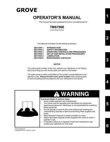
Another important section is the range diagram. The range diagram shows the operating radius and tip height that can be achieved at a given boom length and angle. If the
BOOM ANGLE
HORIZONTAL
OPERATING RADIUS
Terms To Know
operator knows the radius a nd tip height required for a specific lift, the angle and boom length can quickly be determined from the range diagram. Or if he knows the boom length and angle, he can quickly determine the tip height and operating radius.
A lifting diagram is included for over-side, over-rear, and over-front lifting areas. The lifting area diagram shows that the locations of the outrigger stabilizer cylinders in the full extended position are used to mark the boundaries of the lifting areas.
Another section contains notes for lifting capacities. Be sure to read and understand all notes concerning lifting capacities.
The load chart also gives weight reductions for Grove load handling devices such as hookblocks, headache balls, boom extension sections, etc, which must be considered as part of the load. The weight of any other load handling devices such as chains, slings, or spreader bars must also be added to the weight of the load.
NOTE: The information in the following paragraph is an example of how to compute a lift. The numbers used in the example may not coincide with the load chart in the crane cab.
Problem: A concrete beam weighing 2268 kg (5000 lbs) needs to be lifted to a height of 9.1 m (30 ft) at a radius of 15.2 m (50 ft) (maximum). The range diagram indicates the boom must be extended to 18.9 m (62 ft) in order to reach a height of 9.1 m (30 ft) at a radius of 15.2 m (50 ft).
First we need to check the crane for load handling devices. In our example, the crane is equipped with a auxiliary boom nose (rooster sheave) and a five ton headache ball. The rooster sheave is 50 kg (110 lbs), and the headache ball is 78 kg (172lbs) for a total of 128 kg (282 lbs). The lift requires slings and spreader bars weighing 159 kg (350 lbs) which makes the total weight for the load handling devices 286 kg (632lbs).
A check of the load chart for a 15.2 m (50 ft) radius and 19.5m (64ft) of boom length shows a capacity of 3601 kg (7940 lbs) on outriggers over-front and 4970 lbs on outriggers 360 degrees. We subtract the load handling weight of 632 lbs from the load capacity of 3601 kg (7940 lbs) and 2254 kg (4970 lbs). The result is a weight capacity of 3315 kg (7308 lbs) over-the-front and 1968 kg (4338 lbs) for 360 degrees. We are constricted in making the lift over-front only and the boom angle will be about 29 degrees.
Crane Functions
Danger
Death or serious injury could result from improper crane setup on outriggers.
Warning
The outriggers and the center front stabilizer must be properly extended and set and the crane level before any other operation of the crane on outriggers is attempted.
WARNING
When operating the crane on outriggers, the outriggers should always be fully extended or locked in the midextend position, depending on the load chart being used.
WARNING
The center front stabilizer will retract when any main outrigger stabilizer is retracted. Reset center front stabilizer if any main outrigger stabilizer is retracted or extended after initial set-up.
Setting The Outriggers
NOTE: The park brake must be set and the Hydraulic Boost switch must be in the LOW position before the outriggers will operate.
NOTE: The air suspension system must be deflated when on outriggers.
The outrigger control switches are located on the outrigger control box located in a pocket at the front of the superstructure cab. In addition, the outriggers may be operated from optional control boxes mounted on both sides of the carrier just forward of the front outriggers. When using the optional control boxes, the engine speed is increased due to a signal to the engine ECM when the EXTEND/ RETRACT switch is placed in either position.
Caution
Depress outrigger selector switch before the outrigger extension/retraction switch. Failure to do so may cause a hydraulic lock against the individual solenoid valves, and keep them from opening.
1. If outrigger floats are not already installed, remove them from float stowage locations on left, right, and rear of carrier frame. Secure the floats to the rods of the outrigger jack cylinders (aka outrigger stabilizer cylinders) using the levers on each float.
2. Depress the appropriate Outrigger Selector switch to EXTENSION and then position the Outrigger Extension/ Retraction switch to EXTEND. The outrigger beam should begin to extend. Refer to Engaging the MidExtend Lock Pin if the crane is to be operated at the midextend position.
Danger
All four outrigger beams must be equally extended to the mid position vertical stripe or fully extended position before beginning operation.
NOTE: More than one outrigger may be extended at one time. However, each Outrigger Selector switch should be depressed individually and the outrigger extension/retraction switch momentarily positioned to EXTEND to ensure that each outrigger is fully extended.
3. After all four outrigger beams have been extended, depress the appropriate Outrigger Selector switch to STABILIZER and position the Outrigger Extension/ Retraction switch to EXTEND.
4. Extend each stabilizer, until the floats touch the ground. NOTE: More than one stabilizer may be extended at one time.
5. After all floats are on the ground, extend the front stabilizers about 8 to 10 cm (3 to 4 inches) and then extend the back stabilizers the same distance. Repeat until all tires are off the ground.
Danger
All four outrigger beam lock pins must be engaged before operating from the mid-extend position.
Danger
Operator must select proper load chart and LMI program for the outrigger position selected.
6. Repeat step 5 until all wheels are clear of the ground and the crane is level as indicated by the sight level bubble located on the right side of the cab. If it is suspected that the bubble level indicator is out of adjustment, verify and adjust the bubble level as follows: a. Locate the crane on a firm level surface. b. Extend and set the outriggers. Level the crane, as indicated by the bubble level indicator, with the outriggers. c. Place a miracle pointer, carpenter level, or similar type device on a machined surface such as the turntable bearing or bearing mounting surfaces. d. Level the crane with the outriggers as indicated on the device used in step (c). e. Adjust the bubble level indicator with the mounting screws to show level.
Engaging the Mid Extension Lock Pin
1. Turn the locking pin 90° from its stowed position and allow the pin to rest on top of the outrigger beam.
NOTE: It may be necessary to jog the outrigger extension/ retraction switch slightly to ensure proper pin engagement.
2. Slowly extend or retract the outrigger beam, allowing the locking pin to drop into the hole in the top of the outrigger beam, engaging the outrigger beam at the desired length.
Stowing The Outriggers
1. Position the rear Outrigger Selector switches to STABILIZER and position the Outrigger Extension/ Retraction switch to RETRACT until the rear stabilizers have retracted several inches.
2. Position the front Outrigger Selector switches to STABILIZER and position the Outrigger Extension/ Retraction switch to RETRACT until the front stabilizers have retracted several inches.
3. Repeat steps 1 and 2 until the crane is resting on all four wheels and the stabilizer floats are several inches off the ground.
Danger
Keep feet and hands clear of floats when unlocking the floats from the stabilizers.
4. Release the locking levers and allow the floats to drop to the ground.
5. Continue to retract the stabilizers until they are fully retracted.
6. Position the desired Outrigger Selector switch to EXTENSION and hold the Outrigger Extension/ Retraction switch to RETRACT. The appropriate outrigger beam should begin to retract.
NOTE: More than one outrigger beam may be retracted at one time.
7. After all outriggers have been fully retracted, stow the outrigger floats. Secure the floats with quick pins and cotter pins.
Stowing the Mid-Extend Lock Pin
1. Retract the outrigger extension/retraction cylinder.
NOTE: If the lock pin is wedged in the hole in the outrigger beam, it may be necessary to jog the outrigger extension/retraction switch slightly while pulling upward on the pin.
2. Lift the lock pin and turn it 90° to its stowed position.
Setting The Center Front Stabilizer
Caution
Never operate center front stabilizer unless boom is retracted and in boom rest, and outriggers and stabilizers are extended and set. Retract center front stabilizer before stabilizers and outriggers.
1. Position the CENTER FRONT Stabilizer control switch to ACTIVATE and position the outrigger Extension/ Retraction switch to EXTEND.
Caution
Do not try to lift or level the crane with the center front stabilizer.
2. Continue to extend the stabilizer until the float is firmly set on the ground.
Stowing The Center Front Stabilizer
Danger
Center front stabilizer will retract when any main outrigger stabilizer is retracted. Reset center front stabilizer if any main outrigger stabilizer is retracted or extended after initial set-up.
Caution
Only operate center front stabilizer when outriggers are extended and set, and boom is retracted and in boom rest.
1. Position the CENTER FRONT Stabilizer control switch to ACTIVATE and the Extension/Retraction switch to RETRACT.
Danger
Keep feet and hands clear of floats when unlocking the floats from the stabilizers.
2. Fully retract the center front stabilizer. Swinging The Boom
Danger
Death or serious injury could result from being crushed by moving machinery. Sound swing horn and clear all personnel from moving parts.
Danger
Do not elevate or swing boom over side unless outriggers are properly extended and crane is level.
Danger
Clear boom and tail swing path of all obstructions and personnel.
Danger
When swinging from over-the-front to over-the-side, refer to over-the side load chart and make certain the capacity is not exceeded. Traveling with any load over-the-side is prohibited.
Caution
Disengage 360° swing lock, pin swing lock, and swing brake before swinging.
Caution
Never push or pull swing control lever through neutral to the opposite direction to stop swing motion.
To swing the boom, push the SWING control lever to forward for right swing and pull back for left swing. Always operate the control lever with a slow, even pressure. Rotation is stopped utilizing the swing brake foot pedal. When rotation is stopped, put the SWING BRAKE switch in the ON position to prevent further rotation.
Elevating And Lowering The Boom
Danger
Clear area above and beneath boom of obstructions and personnel before elevating or lowering boom.
Elevating the Boom
To elevate the boom, pull the BOOM control lever back, and hold until the boom rises to the desired elevation.
Lowering the Boom
To lower the boom, push the BOOM control lever forward and hold until the boom is lowered to the desired position.
Warning
Long cantilever booms can create a tipping condition even when unloaded and in an extended and lowered position.
Danger
Lower boom and let out cable simultaneously to prevent two-blocking.
Caution
The closer the load is to the boom nose, the more important it becomes to let out cable as the boom is lowered.
Telescoping The Boom
NOTE: When the crane is equipped with an auxiliary hoist the telescope function is controlled by a foot pedal.
Extending The Boom
Warning
When extending the boom, simultaneously let out the cable to prevent two-blocking the boom nose and hook block.
Danger
Check the load chart for maximum load at given radius, boom angle, and length before extending boom with a load.
Caution
Before extending the boom, ensure the large access covers on each side of the boom base section are installed.
Push the TELESCOPE control lever forward away from the operator and hold until the boom extends to the desired length.
Retracting The Boom
Warning
When retracting the boom, the load will lower unless the cable is taken in at the same time.
To retract the boom, pull the TELESCOPE control lever back, toward the operator, and hold until the boom retracts to the desired length.
Telescope Control Pedal
The telescope control pedal is used on cranes equipped with an auxiliary hoist. Push on the top of the pedal to extend the boom and push on the bottom of the pedal to retract the boom.
Lowering And Raising The Hoist Cable
Warning
Keep the area beneath the load clear of all obstructions and personnel when lowering or raising the cable (load).
Warning
Do not jerk control lever when starting or stopping hoist. Jerking causes load to bounce, which could result in possible damage to the crane.
NOTE: When the load is stopped at the desired height, the automatic brake will engage and hold the load as long as the control lever remains in neutral.
Lowering The Cable
Push the MAIN or AUX hoist control lever forward, away from the operator, and hold until the hook or load is lowered to the desired height.
Raising the Cable
Pull the MAIN or AUX hoist control lever back, toward the operator, and hold until the hook or load is raised to the desired height.
Hoist Speed Range Selection
Danger
Do not change the hoist speed range with the hoist rotating.
To change the speed range of the hoist(s), position the applicable switch (MAIN HOIST SPEED or optional AUX HOIST SPEED) to HIGH or LOW as applicable.
Operational Aids
Danger
Electronic equipment on this crane is intended as an aid to the operator. Under no condition should it be relied upon to replace the use of capacity charts and operating instructions. Sole reliance upon these electronic aids in place of good operating practices can cause an accident.
Load Moment Indicator (LMI) System
The Load Moment Indicator (LMI) is an electro-mechanical sensing system designed to alert the crane operator of impending capacity when the system has been properly preset by the operator. The control panel is mounted in the front console of the operator’s cab. When an overload condition is sensed, the system provides the operator with a visual and audible warning, and locks out the control levers to prevent lowering the boom, extending the boom, or raising the main or auxiliary hoist cables.
Three additional features are included within the LMI system:
• Swing Angle Set Limitation
• Work Area Definition
• Anti-two Block Device
Swing Angle Set Limitation allows left and right swing angle to be preset. When the preset angle is reached, the system will provide an audible warning.
Work Area Definition allows the crane operator to describe the crane’s working area by setting up “virtual walls”. They are referred to as virtual walls because they exist in the system and are not real walls. The virtual walls represent obstacles (i.e. buildings, towers, poles, etc.) in the crane’s working range. They are set by defining points along the outer limits of the working area with the tip of the boom. Once the working area has been defined, the system will provide a visual and an audible warning if the boom approaches a virtual wall.
Caution
When defining virtual walls (s). always allow a safe working distance to any obstacles. Never work outside a safe working area as defined by common practice, standards, and manuals.
Warning
There are no cut-outs associated with the swing angle set limitation or the work are definition features.
An Anti-two Block Device is also incorporated into the system to prevent the hook block or headache ball from coming into contact with the boom nose or boom extension. This condition will also cause a lockout of hoist up, boom down, and telescope out, and also provide a visual and an audible alarm.
Refer to the LMI Operator’s Handbook for more detailed information on the function of the LMI system.
Control Lever Lockout System
The control lever lockout system consists of hydraulic solenoid valves (located in the directional control valves) which are in series between the hydraulic remote control valves in the cab and the pilot-operated directional control valves. When the valves are actuated, they prevent pilot flow between the hydraulic remote control valve in the cab and the appropriate directional control valve. The valves are activated in such a manner as to prevent worsening the condition, i.e. boom down, telescope out, or hoist up. The control lever lockout system is used with the anti-two-block system or the load moment indicator (LMI) system.
Crane Travel Operation
Active Restraints
Seat Belts
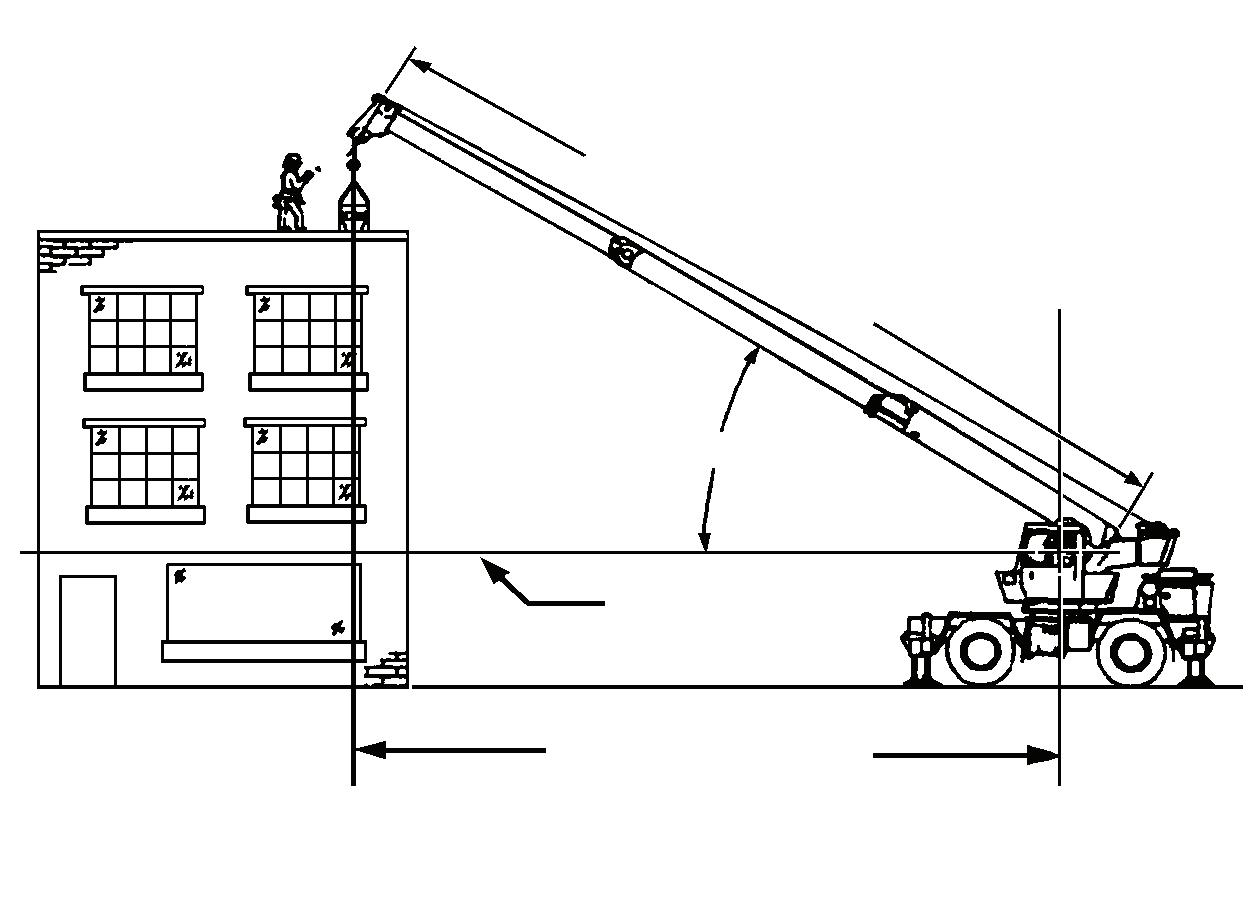
Before fastening a seat belt, always adjust the driver’s seat to the position in which you will drive.
For greater restraint and comfort:
1. Be sure the belt is snugly fitted around the hips - not the waist - and not twisted. Failure to properly fit belts may result in unnecessary injury in the event of a collision.
2. Only one person should be strapped in each seat belt.
To lengthen the belt, tip the buckle end downward, as shown, and pull the buckle until the belt ends can be joined. Insert the belt into the open end of the buckle until a snap is heard and check for latch engagement. The belt can be shortened, after connection, by pulling on the loose end until the belt is snug. Press the buckle release to remove the belt
Traveling - General
Caution
Disengage the hydraulic pumps for extended traveling, cold weather starting, or engine checks.
Caution
Check cold tire pressure prior to extended travel. Refer to tire inflation decal on crane.
Caution
Job site travel with deflated suspension must be limited to 8 kM/H (5 MPH). Attempting to travel at higher speeds may cause drive train component failure.
Do not move the crane until the superstructure has been secured as outlined below.
1. To ensure the axles and/or suspension are not overloaded, adhere to the following.
a. For highway travel with 7484 kg (16,500 lb) of counterweight, install 2495 kg (5500 lb) of counterweight on the carrier. Check that front axle load does not exceed 22,318 kg (49,200 lb) and rear axle load does not exceed 27,216 kg (60,000 lb).
b. GVW should never exceed 49,532 kg (109,200 lb). Also refer to certification label on inside of cab door for Gross Axle Weight Ratio (GAWR).
2. Ensure all boom sections are fully retracted or set to whatever extension is necessary for balance load on the axles.
3. Ensure the boom is fully lowered into the boom rest.
4. Engage the swing brake.
5. Engage the swing lock.
6. Ensure the swingaway, if so equipped, is properly stowed and secured.
7. Remove the hookblock and/or headache ball from the hoist cable(s) and stow securely before traveling or ensure headache ball is properly secured to the tie down provided for that purpose.
8. Ensure the outrigger stabilizers and outrigger beams are fully retracted and the floats are removed.
9. Ensure the center front stabilizer is fully retracted. Floats remain installed.
10. Ensure the stabilizer floats are properly stowed in their holding racks.
11. Ensure the cover doors on the outrigger control panels, battery box, and sling box are closed.
12. Close and/or install all superstructure cab windows and door.
Traveling With Boom Extension And/Or Inserts
Erected
10.1 m (33 ft)/17.1 m (56 ft) Extension a. With the 10.1 m (33 ft) extension and any counterweight, the boom shall be over the front or rear. b. With the 17.1 m (56 ft) extension and 7484 kg (16,500 lb) counterweight only, the boom shall be over the front or rear. c. With the 17.1 m (56 ft) extension and less than 7484 kg (16,500 lb) counterweight, the boom shall be over the front only.
Travel is permissible under the following conditions.
1. The 10.1 m (33 ft) or 17.1 m (56 ft) boom extension shall be erected at minimum offset. If traveling with just the 10.1 m (33 ft) extension, the stinger section must be stowed on the boom base section, not on the extension base section.
2. Jobsite travel only on firm, level surface.
3. Main boom shall be fully retracted.
4. Main boom angle: 0 degrees minimum, 20 degrees maximum.
5. Maximum travel speed: 4 km/h (2.5 mph).
6. Main counterweight (as applicable) shall be installed.
7. Swing lock and pin shall be engaged.
8. Hookblock must be removed from main boom nose.
9. Headache ball may be reeved over boom extension, hanging 0.9 m (3 feet) below sheave.
10. Suspension air bags shall be inflated.
11. The tires shall be properly inflated.
10.1 m (33 ft)/17.1 m (56 ft) Extension Plus 6.1 m (20 ft) Insert a. With the 10.1 m (33 ft) or 17.1 m (56 ft) extension plus insert and 7484 kg (16,500 lb) counterweight only, the boom shall be over the front or rear. b. With the 10.1 m (33 ft) or 17.1 m (56 ft) extension plus insert and less than 7484 kg (16,500 lb) counterweight, the boom shall be over the front only.
Travel is permissible under the following conditions.
1. The 10.1 m (33 ft) or 17.1 m (56 ft) boom extension plus 6.1 m (20 ft) insert shall be erected at minimum offset. If traveling with just the 10.1 m (33 ft) extension and insert, the stinger section must be stowed on the boom base section, not on the extension base section.
2. Jobsite travel only on firm, level surface.
3. Main boom shall be fully retracted.
4. Main boom angle: 0 degrees minimum, 20 degrees maximum.
5. Maximum travel speed: 4 km/h (2.5 mph).
6. Main counterweight (as applicable) shall be installed.
7. Swing lock and pin shall be engaged.
8. Hookblock must be removed from main boom nose.
9. Headache ball may be reeved over boom extension, hanging 0.9 m (3 feet) below sheave.
10. Suspension air bags shall be inflated.
11. The tires shall be properly inflated.
10.1 m (33 ft) Extension Plus 12.2 m (40 ft) Insert a. With the 10.1 m (33 ft) extension plus insert and 7484 kg (16,500 lb) counterweight only, the boom shall be over the front or rear. b. With the 10.1 m (33 ft) extension plus insert and less than 7484 kg (16,500 lb) counterweight, the boom shall be over the front only.
NOTE: Travel with the 17.1 m (56 ft) extension plus 12.2 m (40 ft) insert is not permissible. Travel is permissible under the following conditions.
1. The 10.1 m (33 ft) boom extension plus 12.2 m (40 ft) insert shall be erected at minimum offset. The stinger section must be stowed on the boom base section, not on the extension base section.
2. Jobsite travel only on firm, level surface.
3. Main boom shall be fully retracted.
4. Main boom angle: 0 degrees minimum, 20 degrees maximum.
5. Maximum travel speed: 4 km/h (2.5 mph).
6. Main counterweight (as applicable) shall be installed.
7. Swing lock and pin shall be engaged.
8. Hookblock must be removed from main boom nose.
9. Headache ball may be reeved over boom extension, hanging 0.9 m (3 feet) below sheave.
10. Suspension air bags shall be inflated.
11. The tires shall be properly inflated.
Clutch Operation
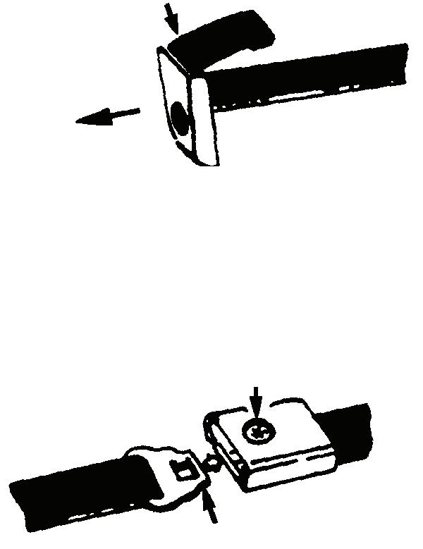
Depress Pedal Last One Inch To Engage Clutch Brake FIGURE3-7
Clutch pedal adjustment provides for approximately 3.8 cm (1.5 in) for free trav el movement of the pedal after the first free travel of 1.27 cm (0.5 in) is passed before engaging the release bearing fully. It is important that this free travel be maintained to avoid possible excessive wear on the bearing and/or clutch slippage. Approximately the last one inch of downward clutch pedal travel engages the clutch brake which overcomes the tendency of the clutch to rotate at high speed when the clutch is disengaged. A slight but definite resistance to clutch pedal downward movement will be felt at the last one inch of travel.
The clutch brake is particularly useful for initial gear engagement in the lower gears when going uphill, when the road speed drops off more quickly than the engine RPM requiring rapid shifts. The clutch brake MUST NOT BE USED when making a downshift.
Clutch engagement should always be made smoothly while synchronizing accelerator movement necessary to move the crane.
Caution
Never fully depress the clutch pedal before the transmission is put in neutral. If the clutch brake is applied with the transmission still in gear, a reverse load will be put on the gears making it difficult to get the transmission out of gear. At the same time, it will have the effect of trying to stop or decelerate the crane with the clutch brake, with resultant rapid wear and generation of excessive heat necessitating frequent replacement of the brake friction discs.
Double clutching is a means of bringing the speed of the transmission gears into synchronization so the shift can be made without clash. The engine is used to speed up the countershaft for a downshift and to slow it down for an upshift. Double clutching operation is accomplished as follows.
1. Depress the clutch (do not engage clutch brake) and shift into neutral.
2. Release clutch pedal and accelerate the engine (when making downshift) or allow engine to slow down (when upshifting) until engine speed approximately corresponds to road speed of the gear ratio selected.
3. Depress the clutch pedal (do not engage clutch brake) and shift into gear.
4. Release the clutch pedal. Always use the double clutching technique.
NOTE: Never allow your foot to ride the clutch pedal when the clutch is engaged. This causes premature release bearing failure and short clutch facing life.
Shifting Gears
Next to concern for safety, good shifting habits are probably the most important capability a driver can have. Knowing how and when to shift can return savings in trip time and operating expense.
In the early stage of moving the crane, keep the engine speed down to the actual power requirement but anticipate the next shift demand and do not cause the engine to labor with the next shift. Start the crane in the lowest gear necessary and with the first few shifts, develop only the RPM needed to get rolling. Then as you upshift, increase crane speed in each gear with a progressive increase in engine speed. It should seldom be necessary to go to governed engine speed in the lower gears except in a peak load situation such as starting up a grade.
The biggest task when climbing a grade generally will be maintaining a reasonable rate of speed. When possible, preplan the climb and probable shift requirements according to traffic conditions and grade to be climbed.
When approaching a hill, gradually move the throttle all the way down if necessary to maintain governed RPM and remain at full throttle as the crane starts up the grade. If there is sufficient power to maintain satisfactory road speed without engine laboring, remain in that gear for the entire grade. Whenever a grade proves too great for the gear that you are in and the engine begins to labor, ease off the throttle as necessary and allow speed to drop off to the next lower shift point before downshifting to the next gear. Speed usually drops off quickly while shifting so the shift should be made rapidly. Additional downshifting should be performed in the same way, as necessary. By riding each gear down to the next shift point, you will get over your grades in the best possible time with minimum shifts.
On downhill operation, the engine provides most efficient braking when run at or near top RPM in the operating range BUT REMEMBER the governor has no control over the engine speed when it is being pushed by a heavy crane. When the engine exceeds the rated governed RPM while descending a grade or downshifting at the high end of the operating range, engine overspeed can result in serious damage. On downhill operation, use the vehicle brakes and gears in combination to keep crane speed under control and the engine below rated governed RPM.
The transmission has 11 forward speeds and three reverse, consisting of a five speed front section and a three speed auxiliary section. The auxiliary section contains low and high range ratios, plus three deep reduction gears. The three lowest (LL1, LO, LL2) gear sets are used for road speed control and are not intended to be used as progressive shifts. The other four ratios are used twice, once in low (LO) range and once in high (HI) range.
As with any transmission gearing, shifting depends on proper synchronization. Adhere to the following:
• Never try to force the gear lever.
• During regular shifts, when moving the gear lever into the next gear position for engagement, the lever should be held lightly against the gear to be engaged.
• If gears are synchronized, engagement will be made immediately.
• If not synchronized, the flat gear teeth will rotate against each other until synchronization is reached.
• Do not jerk the shift lever into the next gear position or try to force gear engagement.
• If gears are out of synchronization, no amount of force is going to make the engagement before synchronization. All shifts are made with one lever and a range control switch which is used only once during an upshift sequence, and only once during a downshift sequence.
In the following instructions, it is assumed that the driver is familiar with motor trucks and tractors, and that he can coordinate the necessary movements of the shift lever and clutch pedal to make progressive and selective gear engagements in either direction, up or down.
Crane Transmission
Initial Start-Up
Caution
Before moving the crane, make sure you understand the shift pattern configuration (see Figure 3-12), or see the decal in the cab.
1. Ensure the shift lever is in neutral and the parking brake is set.
2. Start the engine.
3. Allow air pressure to build up.
4. Apply the service brakes.
5. Ensure the range control switch is down in the low position.
6. If the crane is to be started in deep reduction (LL2 or LL1), move the deep reduction switch forward to IN.
7. Depress the clutch pedal to the floor.
8. Move the shift lever to the desired initial gear.
9. Release the parking brakes.
10. Slowly release the clutch pedal and depress the foot throttle pedal.
Upshifting
Caution
Never move the deep reduction switch or the range control switch with the shift lever in neutral while the crane is moving.
1. To make a deep reduction switch shift from LL2 to 1st, proceed as follows.
a. Just before making the upshift, move the deep reduction switch rearward to OUT while maintaining foot throttle position.
b. Immediately release the foot throttle pedal, depress the clutch pedal once to break torque, release the pedal to engage the clutch, allow the engine to decelerate until the shift is complete. Continue driving or upshifting. The transmission shifts from LL2 to 1st when synchronous is reached.
2. To shift in low range, proceed as follows.
a. Move the shift lever, double clutching, to the next desired gear position in low range (1st to 2nd to 3rd to 4th).
3. To shift from low (4th) to high (5th) range, proceed as follows.
a. When in the last gear position for low range and ready for the next upshift, pull the range control switch up to high and move the shift lever, double clutching, to the next higher gear position. As the shift lever passes through neutral, the transmission will automatically shift from low to high range.
Caution
Never move the shift lever to the low speed gear position after high range preselection, or anytime the transmission is in high range
These ratios are not progressively shifted.
These ratios are progressively shifted.
Do not change range while moving in reverse
Deep Reduction Switch
4. To make a deep reduction switch shift from low range (1st) to low-low range (LL2), proceed as follows.
a. Just before making the downshift, move the deep reduction switch forward to IN while maintaining foot throttle position.
b. Immediately release the foot throttle pedal, depress the clutch pedal once to brake torque, release the pedal to engage the clutch, and depress the foot throttle pedal. The transmission shifts from 1st to LL2 when synchronous speed is reached.
Shifting To Reverse
Caution
Never make a range shift or deep reduction shift while moving in reverse.
1. With the transmission in neutral, determine which reverse range is to be used. Move the range control switch up for high reverse or down for low reverse.
2. Move the shift lever to the reverse position.
4. To shift in high range, proceed as follows.
a. Move the shift lever, double clutching, to the next desired gear position in high range (5th to 6th to 7th to 8th).
Downshifting
Caution
Never move the deep reduction switch or range control switch with the shift lever in neutral while crane is moving.
1. To shift in high range, proceed as follows.
a. Move the shift lever, double clutching, to the next desired gear position in high range (8th to 7th to 6th to 5th).
2. To shift from high (5th) to low (4th) range, proceed as follows.
a. When in the 5th gear position for high range and ready for the next downshift, push the range control switch down to low range and move the shift lever, double clutching, to the next lower gear position. As the shift lever passes through neutral, the transmission will automatically shift from high range to low range.
3. To shift in low range, proceed as follows.
a. Move the shift lever, double clutching, to the next desired gear position (4th to 3rd to 2nd to 1st).
3. To engage deep low reverse, put the range control switch in the down (low) position. Move the deep reduction switch to the forward (IN) position.
4. Carefully release the clutch, making sure deep reverse is fully engaged.
Driving Tips
1. For a smooth start, always select an initial starting gear that will provide sufficient reduction for the load and terrain.
2. On later model cranes, progressively shift the road control ratios.
3. Always use normal double clutching procedures when making lever shifts.
4. Never slam or jerk the shift lever to complete gear engagement.
5. Never coast with the gear shift lever in the neutral position.
6. Never move the deep reduction switch or the range control switch with the gear shift lever in the neutral position while the vehicle is moving.
7. Never make a range shift while operating in reverse.
8. Never downshift at too high of a road speed.
9. When slowing down, the proficient operator can downshift through all the individual gear speeds to prolong the life of the brakes.
10. In most cases, depending on the engine and axle ratios, fuel can be saved by operating the crane at less than governed rpm while in 8th gear.
Rear Tandem Inter-Axle/Cross-Axle Locks
Caution
Do not operate differential locks on dry roads.
To engage the inter-axle or cross axle differential locks for maximum pulling power when approaching slippery or poor road conditions, do the following:
Caution
Do not engage or disengage differential locks while wheels are spinning or at speeds over approximately 16 km/h (10 mph).
1. Stop the crane and position the control lever to the LOCK position.
2. Proceed over the poor road conditions cautiously. When adverse conditions have passed, do the following:
1. Stop the crane and position the control lever to the UNLOCK position.
2. Resume driving at a safe speed.
Service/Parking Brakes
For the most effective braking and maximum life from the brake system components, the following suggestions are made.
1. Air brakes have light pedal operation and the driver is cautioned to use extreme care in application until a good feel is achieved.
2. Use the engine as a brake when approaching a stop or going down a long grade. On a downgrade, use the same transmission gear as would be needed to go up the same grade.
3. When necessary to use brakes to reduce crane speed on downgrades, use a on-and-off application to minimize heat and wear. Do not hold a continuous brake application or slide the wheels.
4. When driving on slippery pavement or under icy conditions, alternately and smoothly apply and release the brakes to prevent skidding.
5. Keep the tires properly inflated. Improperly inflated tires can reduce the efficiency of the brakes.
6. After driving through water, dry the brakes by applying them lightly while maintaining a slow forward speed with an assured clear distance ahead until brake performance returns to normal.
Danger
Stop immediately if low air pressure warning sounds and determine cause of air loss, Stop by downshifting and use engine as a brake. Make final stop using a single brake pedal movement to avoid excessive loss of air and sudden engagement of parking brakes.
NOTE: If the pressure drops below 14 kPa (2psi) per minute with the engine stopped, have the air system checked for leaks.
7. Regularly check the air pressure gauge. System air pressure should never drop below 310 kPa (45 psi). If both systems drop below 310 kPa (45 psi), the automatic spring brakes will actuate. Normal operating pressure is 725 to 825 kPa (105 to 120 psi).
Danger
Do not use parking brake for stopping crane except in case of an emergency, as a severe sudden stop will occur.
Caution
Release brakes before moving crane, or drive train damage will result.
NOTE: Park brake must be set before outrigger controls can be operated.
8. The parking brakes are controlled by a push-pull knob on the front console. Pull the knob out to apply and push the knob in to release the parking brake.
Engine Braking
NOTE: Do not keep a foot lightly on the clutch pedal or the throttle pedal. This will cause the engine brake not to come on.
By energizing the engine brake, the power producing diesel engine, in effect, becomes a power absorbing air compressor. To retard a crane on a downgrade using the Engine Brake, the operator selects a gear which will provide a balance between engine speed and road speed, then engages the engine brake. If the engine speed exceeds maximum rated rpm for a desired speed, a lower gear can be selected or intermittent use of the service brakes can be made. This selection of a lowe r gear will generally allow complete control of the crane by the engine brake leaving the service brakes in reserve to be used for emergency stops.
With the engine brake turned on, the engine brake will not be energized until the momentum is driving the engine.
1. Position the ENGINE BRAKE On/Off switch to ON.
2. Position the ENGINE BRAKE High/Low switch to either position, depending on the amount of braking desired.
3. Leave off the throttle to activate the engine braking system and slow the crane.
NOTE: The engine braking system will automatically deactivate when the throttle is depressed.
Caution
Before engaging engine brake on slippery roads, be sure crane is maintaining traction.
Stowing and Parking
Danger
Never park crane near holes, on rocky surfaces, or on soft spots. This may cause crane to overturn, resulting in injury or death to personnel.
When parking the crane, do the following.
1. Remove the load from the hook.
2. Remove or stow boom extensions if so equipped.
3. Fully retract all boom sections.
4. Lower the boom to normal travel position.
5. Engage the swing brake, swing lock pin, and 360 degree house lock.
6. Retract all stabilizer cylinders and outrigger beams.
7. Turn off CRANE FUNCTION power switch.
8. Park the crane on a stable surface.
9. Apply the parking brakes and if necessary, chock wheels.
10. Ensure all operating controls are in neutral position.
11. Shut down engine following proper procedures specified in this handbook and the applicable engine manual.
12. Remove the keys.
13. Close and lock, if applicable, all windows, covers, and doors.
Crane Shutdown Procedures
The following procedures will extend serviceable life of various crane components, reduce vandalism, and accidents during crane shutdown periods or anytime the crane is left unattended.
1. Perform the procedures found under Shutdown Procedure in this handbook.
Danger
Never park crane near holes, on rocky surfaces, or on soft spots. This may cause crane to overturn, resulting in injury or death to personnel.
2. Park the crane on a proper surface with the outrigger stabilizers and beams fully retracted. Do not park in a location where it may become frozen to the ground or settle unevenly and overturn.
3. Apply parking brakes and if necessary, chock the wheels.
4. Position all controls to neutral or off.
5. Shut down the engine using the proper procedures as specified by this Handbook and the engine manual.
6. Perform any other specified procedures required at the end of the workday, i.e., drain water from the fuel filterwater separator, refueling, etc.
7. Close all windows.
8. Remove the keys from the crane.
9. Lock up the crane. Install vandal guards, if used.
Danger
Step 10 does not take the place of the prestarting checks which must be performed just prior to using the crane at the next working day.
10. Make a thorough walk around inspection to ensure that all cylinders that can be retracted are retracted. The only exceptions are those cylinders which cannot be fully retracted, i.e., steer cylinders. Also, look for anything that could hinder or prevent starting the next day’s work.
Unattended Crane
WARNING
Tipping Hazard!
Changing weather conditions including but not limited to: wind, ice accumulation, precipitation, flooding, lightning, etc. should be considered when determining the location and configuration of a crane when it is to be left unattended.
Failure to comply with these instructions may cause death or serious injury.
The configuration in which the crane should be left while unattended shall be determined by a qualified, designated individual familiar with the job site, configuration, conditions, and limitations.
Section 4
Section 4
SET-UP AND INSTALLATION PROCEDURES
General
This section provides procedures for installing the hoist cable on the hoist drum, cable reeving, and erecting and stowing the boom extension, and removal and installation of the counterweight.
Installing Cable On The Hoist
Caution
If cable is wound from the storage drum, the reel should be rotated in the same direction as the hoist.
NOTE: The cable should preferably be straightened before installation on the hoist drum.
Install cable on the hoist drum in accordance with the following procedure.
1. Position the cable over the boom nose sheave and route to the hoist drum.
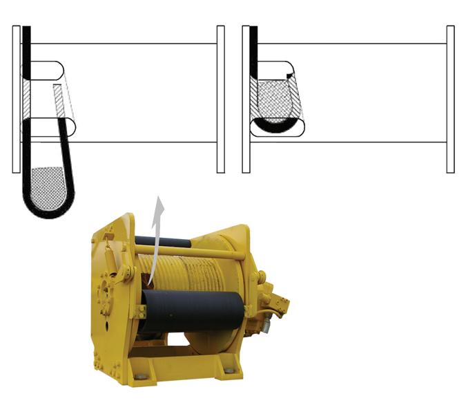
2. Position the hoist drum with the cable anchor slot on top.
3. Insert the cable through the slot and position around the anchor wedge (1) (Figure4-1).
NOTE: The end of the cable should be even with the bottom of the slot for the anchor wedge.
4. Position the anchor wedge in the drum slot; pull firmly on the free end (2) of the cable to secure the wedge.
NOTE: If the wedge does not seat securely in the slot, carefully tap (3) the top of the wedge with a mallet.
5. Slowly rotate the drum, ensuring the first layer of cable is evenly wound onto the drum.
6. Install the remainder of the cable, as applicable.
Cable Reeving
NOTE: There are two types of cable (wire rope) available on this crane; 6x37 and 35 x 7 (non-rotating).
Within the limits of the load and range charts and permissible line pull, multi-part lines allow the operator to raise a greater load than can be raised with a single part line. Various cable reeving (part line) is possible with the boom nose and hook block. This reeving should be accomplished by a qualified rigger using standard rigging procedures (Figure4-3)
In order to quick reeve the hook block without removing the wedge socket on the end of the cable, (Figure4-2).
UPPER BOOM NOSE SHEAVES
BOTTOM BOOM NOSE SHEAVES
4th SHEAVE OPTIONAL ON RT750E STANDARD OR RT760E
5th
ONLY